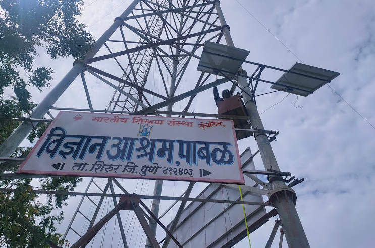
Objective : To make signboard or hoarding visible in darkness with solar flood light system.
Introduction: Solar Lightning systemcomes with LEDs, Batteries, Solar panel and charge controller. Which is used in flood lights, signboard lights, hoarding lights, etc. In remote location like highways, jungles, etc. there are many signboards, hoardings but due to darkness at night they are not visible, so we can have trouble due to absence of lights, solar lightning system provides continuous power supply to flood lights and LEDs so the display boards can be seen clearly, so we avoid the troubles causes due to absence of light.
Design:
- Solar Panel : 3 Nos each of 100 W
- Battery : 3 Nos each of 40 Ah
- Charge Controller : 1 No MPPT type
- LED lamp : 3 Nos each of 50 W
Design of Display Board :


Wind load calculation :
These wind load calculation were referred from handbook of Wind load on building and structure by IIT Kanpur.
Link – https://www.google.com/url?sa=t&source=web&rct=j&url=https://www.iitk.ac.in/nicee/IITK-GSDMA/W02.pdf&ved=2ahUKEwjjs7j9iI3qAhWXb30KHemhBBsQFjAXegQIARAL&usg=AOvVaw05RqQ8QFAJEhpwg0foWuIN
Wind speed: (Vb) = 37 m/s
Terrain category : Rural
- Risk factor coefficient K1 = 0.92
- Terrain & height factor K2 = 1.15
- Topography factor K3 = 1.0
- Importance of cyclone region K4 = 1.15
- Wind directionality factor Kd= 0.90
- Area averaging factor Ka = 1.0
All the values has been taken from handbook.
Design Wind speed :
Vz = Vb k1 k2 k3 k4
Vz = 37*0.92*1.15*1*1.15= 45.0179 m/s
Design wind pressure :
Pz = 0.6 * ( Vz)square = 0.6* 45.02*45.02
Pz = 1216.08 N/ m2
Pd = Pz* ka* kd= 1216.08*0.9*1 = 1.094 KN/m2
Wind force on Board :
F = cf * A* Pd
Where cf is drag coefficient which taken from IS875 table No. 21
Cf = 1.2
Therefore F = 1.2* 3.54 * 1.094 = 3.93 KN
Stress calculations
By considering the force acting on the frame , the stress action on the board is calculated by ANSYS software.


MS material mechanical properties:
- Hardness : 126 BHN
- Ultimate tensile strength: 440MPa
- Yield strength : 370 MPa
Factor of safety : Ultimate stress / working stress
4.40e6/ 4.34e6 = 1.013
As we do not have any records of 140 km/hr airflow in Pabal region, so we need not consider the same.
At 60 Km/hr the stress is calculated as 1.53e6 KN
So, Factor of safety = 4.40e6/ 1.53e6 = 2.87
So, the structure is safe from the wind load.


The major task was to mount the board on tower. The mounting structure and clamps should be strong enough to sustain the weight of the board. The force distribution along all four sides must be same to withstand the load. Some solutions were suggested for the clamping :
- Clamping with U bolts and extended L angle from all four ends.

In the above figure we can see that all the four ends of the are welded with L angle and L angle is supported by flat plate throughout. But in the above design frame is supported at the ends only, the middle portion of the frame is not supported by this design. Therefore, there are chances of shear in welded joint due it’s weight or L angle may get bent due to its overhanging design, so this design were rejected.
2. Clamping with U bolts and Square tube welded throughout the frame.

In above figure we can see that a square tube supporting the whole frame with welded joints.
At that time we were having two option to support one is square tube and another is circular tube; so we need to select one of them for our final solution. Comparison between square tube and circular tube same material, length, thickness, area of cross section, force:
Area of square tube with side h : A= h²
Moment of inertia of square tube : I= h^4/12
Area for circular section with radius r is: A = π*r²
Moment of inertia for circular section : I = π*r^4/4
As two areas are equal,
h²= π*r² or r= h√π
Put this value of r in circular section:
I = π*r^4/4 = h^4/4π = h^4/ 12.57
and I for square tube is,
I = h^4/12 which is greater than circular section
The higher value of I for square tube section means the bending stress will be lower at any point on the square C/S compared to circular C/S and square section will be more efficient.


Factor of safety : Yield stress/ working stress = 240 Mpa/ 14 Mpa = 15
from the above calculation we can say that at a applied force the square tube supported structure is safe.
but the required sized square tube is not available in market in Pabal, so another option were chosen. Instead of square tube L angle is selected for the same. Stress calculations for L angle:
M/I = σ/y = E/R
Where, M= bending moment,
I=Moment of inertia of the area of cross section.
σ=Bending stress
y=distance of extreme fibre from the neutral axis
E=Young’s modulus
R=radius of curvature.
For 35*35*5 L angle,
M max= wL/4 = (3400*6095)/4 = 5.1* 10^6 N-mm
Ixx = 3.5 cm^4 … from ISO standards handbook
Y max = I/ Z = 3.5/1.4 = 2.5 cm^3
σ = (Mmax * Y max)/ Ixx = ( 5.18 * 10^6 *2.5)/ 3.5 = 37 N/ mm² = 37 MPa
Factor of safety : 240/37 = 7 at yield strength.
Therefore from the above calculation the structure is safe.

U bolt size selection:
When bolt is subjected to tensile load:
Pt = σ t* As
Pt – Tensile load
σ – maximum allowable stress
As – Bolt effective C/S area
Pt = 3540 N
As = Pt/ σ t = 3540/ 640 = 5.53 approximately = 6
We selected 12 mm² and selected the M10 diameter bolt as per market availability and higher strength than required. The manual for Guidelines for U bolt design were referred to make U bolt of our required dimensions.

The material selected for making U bolt is low carbon steel, which is used in application for structures. The threads we plotted with help of threading die . these bolts were supported by 50* 5 mm flat plate clamping.


safety measures
Chances of accident are higher with object with heavy load is mounted on towers. In remote location no one is there to keep watch on the systems. If any accident occurred there are fatal chances, so instead of being confident on primary safety, we should also look at secondary safety measures. If primary safety failed due to some accident the secondary safety should help the system to sustain.
In this case the clamps are in primary safety and metal chain is in secondary safety.
If clamp fails, the chain will take the load and accident would be prevented.
Project document:
https://docs.google.com/document/d/1adrh7BcLg1oHyy151nvljuOjT9PeXZUj4gaNzANyuFQ/edit?usp=drivesdk
