Introduction
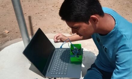
In this assignment, I explored how communication works between two PCB boards. I learned how the TX (Transmit) and RX (Receive) pins are used to send and receive data through wired communication. I also experimented with sending data to ThingSpeak for IoT applications. This assignment helped me understand how devices communicate with each other and exchange data efficiently, providing practical experience with both wired communication and cloud-based IoT platforms.

Individual assignment
Task:
Design and connect wire and wireless node with network and local input and output device.
Group assignment
Task:
Communication between two microcontroller board.
Networking and communications

Network and communication allow devices to connect and share information with each other. A network is a group of connected devices, such as computers, smartphones, sensors, and microcontrollers, that exchange data through wired or wireless connections.
Communication is the process of sending and receiving data between these devices. Wired communication uses cables like Ethernet or serial connections (TX and RX), while wireless communication uses technologies such as Wi-Fi and Bluetooth.
Network and communication are used in many areas, including homes, schools, businesses, industries, and IoT (Internet of Things) systems. They make it possible to share files, access the internet, control smart devices, and monitor data remotely.
In simple terms, network and communication help devices work together efficiently, making data sharing faster, easier, and more reliable.
Embedded Networking

Embedded networking is the process of connecting embedded devices so they can communicate and share data with each other or with the internet. An embedded device is a small computer system designed to perform a specific task, such as controlling sensors, motors, displays, or other electronic components.
Embedded devices can communicate through wired connections, such as UART, SPI, or I2C, or through wireless technologies, such as Wi-Fi, Bluetooth. These communication methods allow devices to exchange data, monitor system status, and respond to commands in real time.
Embedded networking is widely used in IoT (Internet of Things) applications, smart homes, industrial automation, healthcare, agriculture, and smart cities. It enables devices to collect data, process information, and send it to cloud platforms for remote monitoring and control.
In simple terms, embedded networking allows multiple devices to work together efficiently. It improves communication, automation, and data sharing, making modern electronic systems smarter, faster, and more reliable.
Types of communication:-
- Wired communication
- Wireless communication
Wired communication
Wired communication is the transfer of data between devices using physical cables. It provides a stable and reliable connection with high data transfer speed. Common wired communication methods include UART, SPI, and I2C. It is widely used in computers, industrial systems, and embedded devices where reliable communication is required. Wired communication is secure and less affected by interference compared to wireless communication.
Applications of Wired Communication
- Computer and office networks using Ethernet cables.
- Communication between microcontrollers using UART, SPI, and I2C.
- Industrial automation and factory control systems.
- CCTV surveillance and security systems.
- Data transfer between computers, sensors, and embedded devices.
Wireless communication
Wireless communication transfers data between devices without using physical cables. It uses radio waves or electromagnetic signals to connect devices over short or long distances. Common wireless technologies include Wi-Fi and Bluetooth. It is widely used in smartphones, IoT devices, smart homes, and remote monitoring systems. Wireless communication offers flexibility and easy installation but may be affected by signal interference.
Applications of Wireless Communication
- Smart home devices such as smart lights and security cameras.
- IoT (Internet of Things) systems for remote monitoring and control.
- Mobile phones, tablets, and laptops using Wi-Fi and Bluetooth.
- Wireless sensor networks in agriculture and healthcare.
- GPS navigation, wearable devices, and industrial automation.
Information about UART, SPI, I2C
1)UART (Universal Asynchronous Receiver/Transmitter)

UART is a serial communication protocol used to exchange data between two devices. It uses two main pins: TX (Transmit) to send data and RX (Receive) to receive data. UART does not require a clock signal because both devices communicate using the same baud rate. It is simple, reliable, and commonly used for communication between microcontrollers, sensors, and computers.
Applications
- Bluetooth modules (HC-05/HC-06)
- GPS modules
- GSM modules
- Communication between a microcontroller and a computer (serial port)
2)SPI (Serial Peripheral Interface)

SPI is a high-speed serial communication protocol used to connect a microcontroller with peripheral devices. It uses four main lines: MOSI, MISO, SCK (Clock), and CS (Chip Select). SPI allows fast and full-duplex communication, meaning data can be sent and received at the same time. It is widely used with displays, memory cards, sensors, and other embedded devices.
Applications
- EEPROM memory
- RTC (Real-Time Clock) modules
- Temperature and pressure sensors
- OLED displays
- Accelerometers and gyroscope
3) I2C (Inter-Integrated Circuit)

I2C is a serial communication protocol that allows multiple devices to communicate using only two wires: SDA (Serial Data) and SCL (Serial Clock). It supports multiple master and slave devices on the same bus, making it ideal for connecting sensors and peripherals. I2C is simple, requires fewer pins, and is commonly used in embedded systems, IoT devices, and development boards.
Applications
- SD card modules
- TFT/LCD displays
- Flash memory
- ADC/DAC converters
- Sensor
Camparison of UART,SPI and I2C
| Feature | UART | SPI | I²C |
|---|---|---|---|
| Full form | Universal Asynchronous Receiver/Transmitter | Serial Peripheral Interface | Inter-Integrated Circuit |
| Communication | Serial | Serial | Serial |
| Type | Wired | Wired | Wired |
| Number of wires | 2 (TX, RX) + GND | 4 (MOSI, MISO, SCLK, CS) | 2 (SDA, SCL) |
| Clock | No (Asynchronous) | Yes | Yes |
| Devices supported | 2 devices | One master, multiple slaves | Multiple masters and multiple slaves |
| Speed | Medium | Very high | Moderate |
| Complexity | Simple | Moderate | Simple |
Wireless communication

Wireless communication is the process of transmitting data between devices without using physical cables. It uses radio waves, infrared, or other electromagnetic signals to exchange information. Common wireless technologies include Wi-Fi and Bluetooth. Wireless communication is widely used in IoT devices, smartphones, smart homes, industrial automation, and remote monitoring systems. It provides flexibility, easy installation, and mobility, making it ideal for connecting devices over short or long distances.
IOT Communication

IoT (Internet of Things) communication is the process of connecting smart devices to exchange data with each other and with cloud platforms over the internet. These devices use communication technologies such as Wi-Fi and Bluetooth to send and receive information. IoT communication enables real-time monitoring, remote control, and automation of devices. It is widely used in smart homes, healthcare, agriculture, industrial automation, and environmental monitoring. IoT communication helps improve efficiency, reduce manual effort, and support data-driven decision-making.
Group assignment
Communication between two microcontroller boards allows them to exchange data and work together to perform different tasks. The boards communicate using communication protocols such as UART, SPI, or I2C. One microcontroller sends data, while the other receives and processes it. This type of communication is commonly used in embedded systems, robotics, IoT devices, and industrial automation. It improves system performance by allowing multiple devices to share information and coordinate their operations efficiently.

Task
Send a message between two projects.
Communication Protocol:
Communication protocols are a set of rules that allow different devices to exchange information properly. Similar to traffic rules that manage the movement of vehicles, these protocols control how data is transmitted and received between devices. They ensure that devices can communicate accurately, even if they are made by different manufacturers.
TCP/IP Protocol:
TCP/IP is one of the most widely used communication protocols for connecting devices over the internet. It divides data into smaller units called packets, transfers them through the network, and reassembles them at the receiving end. This process helps ensure reliable and accurate data communication.
Serial vs Parallel Communication
Serial Communication:

Serial communication transfers data one bit at a time through a single channel. It uses fewer wires and is commonly used for communication between microcontrollers and sensors. Examples include UART, SPI, and I2C.
Parallel Communication:.

Parallel communication transfers multiple bits of data at the same time using multiple communication lines. It provides faster data transfer but requires more wires and is mainly used for short-distance communication
Transmission modes:
1. Simplex Mode:

In simplex mode, data is transmitted in only one direction. The receiver cannot send data back to the sender.
2. Half-Duplex Mode:

In half-duplex mode, data can flow in both directions, but only one device can transmit at a time. Devices communicate by taking turns.
3. Full-Duplex Mode:
In full-duplex mode, data can be transmitted and received simultaneously in both directions.
Example: Mobile phone communication

In full-duplex mode, data can be transmitted and received simultaneously in both directions.
Synchronous vs Asynchronous Communication

Synchronous Communication:
In synchronous communication, data is transferred continuously with the help of a common clock signal between devices. The sender and receiver are synchronized, which allows faster and more accurate data transfer.
Example: SPI, I2C.
Asynchronous Communication:
In asynchronous communication, data is transferred without a shared clock signal. Data is sent using start and stop bits to identify the beginning and end of transmission.
Example: UART, RS-232


Code :-
Sender Code
#include <WiFi.h>

const char* ssid = "YOUR_HOTSPOT_NAME";
const char* password = "YOUR_PASSWORD";

const char* serverIP = "192.168.43.100";   // Change to Receiver ESP32 IP

void setup() {
  Serial.begin(115200);

  WiFi.begin(ssid, password);
  while (WiFi.status() != WL_CONNECTED) {
    delay(500);
    Serial.print(".");
  }

  Serial.println("\nConnected");
}

void loop() {
  WiFiClient client;

  if (client.connect(serverIP, 80)) {
    client.println("Hello from ESP32");
    client.stop();
  }

  delay(2000);
}
Receiver Code
#include <WiFi.h>

const char* ssid = "YOUR_HOTSPOT_NAME";
const char* password = "YOUR_PASSWORD";

WiFiServer server(80);

void setup() {
  Serial.begin(115200);

  WiFi.begin(ssid, password);
  while (WiFi.status() != WL_CONNECTED) {
    delay(500);
    Serial.print(".");
  }

  Serial.println("\nConnected");
  Serial.println(WiFi.localIP());

  server.begin();
}

void loop() {
  WiFiClient client = server.available();

  if (client) {
    while (client.connected()) {
      if (client.available()) {
        String msg = client.readStringUntil('\n');
        Serial.print("Received: ");
        Serial.println(msg);
      }
    }
    client.stop();
  }
}
We Use Wired Communication Interfaces in ESP32-C3 Board


Code:-
Board 1
#include <HardwareSerial.h>

HardwareSerial mySerial(1);

void setup() {
  Serial.begin(115200);
  mySerial.begin(9600, SERIAL_8N1, 20, 21);   // RX, TX
  Serial.println("Type a message and press Enter:");
}

void loop() {

  // Send message typed in Serial Monitor
  if (Serial.available()) {
    String msg = Serial.readStringUntil('\n');
    msg.trim();

    mySerial.println(msg);

    Serial.print("You: ");
    Serial.println(msg);
  }

  // Receive reply
  if (mySerial.available()) {
    String reply = mySerial.readStringUntil('\n');
    reply.trim();

    Serial.print("Board2: ");
    Serial.println(reply);
  }
}
Board 2
#include <HardwareSerial.h>

HardwareSerial mySerial(1);

void setup() {
  Serial.begin(115200);
  mySerial.begin(9600, SERIAL_8N1, 20, 21);   // RX, TX
  Serial.println("Ready");
}

void loop() {

  // Receive message
  if (mySerial.available()) {
    String msg = mySerial.readStringUntil('\n');
    msg.trim();

    Serial.print("Board1: ");
    Serial.println(msg);
  }

  // Send reply typed in Serial Monitor
  if (Serial.available()) {
    String reply = Serial.readStringUntil('\n');
    reply.trim();

    mySerial.println(reply);

    Serial.print("You: ");
    Serial.println(reply);
  }
}
About Thingspeak
ThingSpeak is an IoT (Internet of Things) cloud platform that helps devices send, store, and display data over the internet. It allows users to monitor sensor data in real time from anywhere. Microcontrollers such as ESP32, Arduino, and Raspberry Pi can send data to ThingSpeak using Wi-Fi or Ethernet. The data is stored in channels and displayed as easy-to-read graphs and charts.ThingSpeak is commonly used to monitor temperature, humidity, light, and other sensor values. It is widely used in smart homes, agriculture, healthcare, weather stations, and industrial automation.In simple terms, ThingSpeak helps IoT devices connect to the cloud, making it easy to store, view, and analyze data from anywhere in the world.
The process I followed is as follows:-

Step1 :- First, I searched for ThingSpeak and opened the website.

Step2 :- I selected the “Get Started for Free” option to create a free ThingSpeak account, which helps us store and monitor sensor data through visualizations.


Step3 :-Next, I signed in and created an account using my email ID and password.This is required because ThingSpeak (by MathWorks) needs a user account to store our project data securely online.


Step4 :-Then, I create mathworks account.

Step 5: After setting up the MathWorks account, I accessed the ThingSpeak dashboard and selected the “Create Channel” option. A channel is used as a storage space for collecting and organizing the sensor data received from the project.

Step 6: I named the channel “Temperature and Humidity Monitor” and provided a suitable description to make the project easier to recognize in the future. After that, I created two fields: Temperature and Humidity. These fields are used to store separate sensor readings, allowing each type of data to be recorded and displayed properly.

Step 7: Finally, I saved the created channel to apply the settings and start storing the sensor data in ThingSpeak.

Step 8: After saving the channel, the channel dashboard displayed statistics and graph sections. These graphs help in monitoring and analyzing the sensor readings, as ThingSpeak automatically converts the collected data into visual charts.

Step 9: Next, I opened the API Keys section and copied the Write API Key. This key is required to allow the device or program to send sensor data to the ThingSpeak channel.

Step 10: I used the Write API Key in the program because it works as an authentication code that permits the microcontroller to upload sensor readings to the ThingSpeak channel. I also entered the WiFi SSID and password in the code so that the ESP32 could connect to the network and transmit data online.
Code I used is as follows:-
#include <WiFi.h>
#include <HTTPClient.h>
#include <DHT.h>

// ------------ DHT22 ------------
#define DHTPIN 9          // Change if required
#define DHTTYPE DHT22

DHT dht(DHTPIN, DHTTYPE);

// ------------ WiFi -------------
const char* ssid = "YOUR_WIFI_SSID";
const char* password = "YOUR_WIFI_PASSWORD";

// -------- ThingSpeak ----------
String apiKey = "YOUR_THINGSPEAK_WRITE_API_KEY";

void setup() {
  Serial.begin(115200);
  delay(1000);

  dht.begin();

  Serial.println("================================");
  Serial.println("Connecting to WiFi...");

  WiFi.mode(WIFI_STA);
  WiFi.begin(ssid, password);

  while (WiFi.status() != WL_CONNECTED) {
    Serial.print(".");
    delay(500);
  }

  Serial.println("\nWiFi Connected!");
  Serial.print("IP Address : ");
  Serial.println(WiFi.localIP());
}

void loop() {

  float temperature = dht.readTemperature();
  float humidity = dht.readHumidity();

  if (isnan(temperature) || isnan(humidity)) {
    Serial.println("Failed to read DHT22 Sensor!");
    delay(2000);
    return;
  }

  Serial.println("--------------------------------");
  Serial.print("Temperature : ");
  Serial.print(temperature);
  Serial.println(" °C");

  Serial.print("Humidity    : ");
  Serial.print(humidity);
  Serial.println(" %");

  if (WiFi.status() == WL_CONNECTED) {

    HTTPClient http;

    String url = "http://api.thingspeak.com/update?api_key=" + apiKey +
                 "&field1=" + String(temperature, 2) +
                 "&field2=" + String(humidity, 2);

    Serial.println("Sending Data to ThingSpeak...");
    Serial.println(url);

    http.begin(url);

    int httpResponseCode = http.GET();

    if (httpResponseCode > 0) {
      Serial.print("HTTP Response Code : ");
      Serial.println(httpResponseCode);

      if (httpResponseCode == 200) {
        Serial.println("Data Sent Successfully to ThingSpeak!");
      }
    } else {
      Serial.print("Error Code : ");
      Serial.println(httpResponseCode);
      Serial.println("Failed to Send Data!");
    }

    http.end();

  } else {
    Serial.println("WiFi Disconnected!");
  }

  Serial.println("--------------------------------");

  // ThingSpeak requires at least a 15-second delay
  delay(20000);
}
Explanation:
#include <WiFi.h>
#include <HTTPClient.h>
#include <DHT.h>

// ------------ DHT22 ------------
#define DHTPIN 9
#define DHTTYPE DHT22

DHT dht(DHTPIN, DHTTYPE);

// ------------ WiFi -------------
const char* ssid = "YOUR_WIFI_SSID";
const char* password = "YOUR_WIFI_PASSWORD";

// -------- ThingSpeak ----------
String apiKey = "YOUR_THINGSPEAK_WRITE_API_KEY";
Explanation:
This section includes the required libraries for Wi-Fi communication (WiFi.h), HTTP requests (HTTPClient.h), and DHT22 sensor operation (DHT.h). The DHT22 sensor pin and sensor type are defined, and a DHT object is created. Variables for the Wi-Fi SSID, password, and ThingSpeak Write API key are also declared using placeholder values that should be replaced with the user’s own credentials.
void setup() {
  Serial.begin(115200);
  delay(1000);

  dht.begin();

  Serial.println("================================");
  Serial.println("Connecting to WiFi...");

  WiFi.mode(WIFI_STA);
  WiFi.begin(ssid, password);

  while (WiFi.status() != WL_CONNECTED) {
    Serial.print(".");
    delay(500);
  }

  Serial.println("\nWiFi Connected!");
  Serial.print("IP Address : ");
  Serial.println(WiFi.localIP());
}
Explanation:
The setup() function runs only once when the ESP32 starts. It initializes serial communication at 115200 baud for displaying messages on the Serial Monitor and initializes the DHT22 sensor. The ESP32 is configured in station mode and attempts to connect to the specified Wi-Fi network using the provided SSID and password. The program waits until the connection is successful and then displays the assigned IP address, confirming that the ESP32 is connected to the network
float temperature = dht.readTemperature();
float humidity = dht.readHumidity();

if (isnan(temperature) || isnan(humidity)) {
  Serial.println("Failed to read DHT22 Sensor!");
  delay(2000);
  return;
}

Serial.println("--------------------------------");
Serial.print("Temperature : ");
Serial.print(temperature);
Serial.println(" °C");

Serial.print("Humidity    : ");
Serial.print(humidity);
Serial.println(" %");
Explanation:
This section reads the temperature and humidity values from the DHT22 sensor using the readTemperature() and readHumidity() functions. The isnan() function checks whether the sensor readings are valid. If invalid data is detected, an error message is displayed, the program waits for two seconds, and then retries. If the readings are valid, the measured temperature in degrees Celsius and humidity in percentage are displayed on the Serial Monitor.
if (WiFi.status() == WL_CONNECTED) {

  HTTPClient http;

  String url = "http://api.thingspeak.com/update?api_key=" + apiKey +
               "&field1=" + String(temperature, 2) +
               "&field2=" + String(humidity, 2);

  Serial.println("Sending Data to ThingSpeak...");
  Serial.println(url);

  http.begin(url);

  int httpResponseCode = http.GET();

  if (httpResponseCode > 0) {
    Serial.print("HTTP Response Code : ");
    Serial.println(httpResponseCode);

    if (httpResponseCode == 200) {
      Serial.println("Data Sent Successfully to ThingSpeak!");
    }
  } else {
    Serial.print("Error Code : ");
    Serial.println(httpResponseCode);
    Serial.println("Failed to Send Data!");
  }

  http.end();

} else {
  Serial.println("WiFi Disconnected!");
}

delay(20000);
Explanation:
This section checks whether the ESP32 is connected to the Wi-Fi network. If the connection is available, an HTTPClient object is created and a URL is generated containing the ThingSpeak Write API key, temperature value (field1), and humidity value (field2). The ESP32 sends the data to the ThingSpeak server using an HTTP GET request. The server returns an HTTP response code, which is checked to verify whether the upload was successful. If the response code is 200, the data has been uploaded successfully; otherwise, an error message is displayed. Finally, the program waits for 20 seconds before sending the next set of sensor readings, satisfying ThingSpeak’s minimum 15-second update interval.
Pin connections
| DHT11 Pin | ESP32 Connection |
|---|---|
| VCC | 5V |
| DATA | GPIO4 |
| GND | GND |

I used DHT22 Temperature and Humidity sensor

The temperature and humidity values were successfully uploaded to ThingSpeak..

The image shows the temperature and humidity data displayed as graphs on the ThingSpeak channel.
Individual assignment
LED Blinking Control Using Bluetooth and Aurdino
This task demonstrates controlling an LED using serial Bluetooth communication with an Arduino board. The Bluetooth module communicates with the Arduino through the serial interface to receive commands from a mobile device. Based on the received Bluetooth data, the Arduino controls the LED to turn ON and OFF. This project helps in understanding wireless communication and Bluetooth-based device control using Arduino.


Code for this I use
#include <SoftwareSerial.h>

SoftwareSerial BT(10, 11);   // RX, TX

const int ledPin = 13;
char command;

void setup() {
  pinMode(ledPin, OUTPUT);
  digitalWrite(ledPin, LOW);

  Serial.begin(9600);
  BT.begin(9600);

  Serial.println("Bluetooth LED Control Ready");
}

void loop() {
  if (BT.available()) {
    command = BT.read();

    Serial.print("Received: ");
    Serial.println(command);

    if (command == '1') {
      digitalWrite(ledPin, HIGH);
      BT.println("LED ON");
    }

    if (command == '0') {
      digitalWrite(ledPin, LOW);
      BT.println("LED OFF");
    }
  }
}