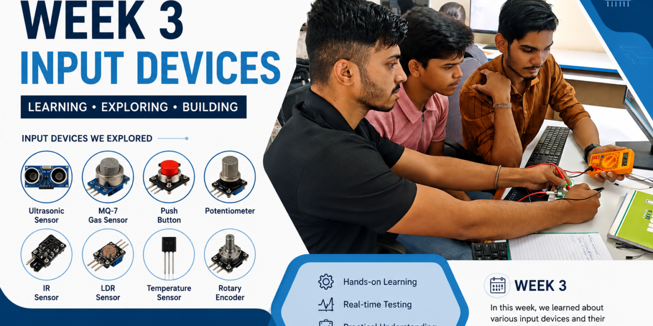
introduction
In Week 3, our target was to study different types of input sensors and understand their working principles. We learned how sensors detect physical changes such as temperature, light, sound, motion, gas, humidity, pressure, magnetic fields, and touch, and convert them into electrical signals that a microcontroller can process.
We also studied the internal structure of different sensors, including the materials and sensing elements used inside them. This helped us understand how each sensor detects specific physical changes and generates an electrical output. we learned the difference between analog and digital sensors,
Through this study, we gained knowledge about the working principle, internal construction, pin configuration, applications, and interfacing of various input sensors with a microcontroller.
Input Devices
Input devices are electronic components or sensors that detect changes in the environment or receive user input and convert them into electrical signals that a microcontroller or computer can process. They provide the data required for a system to make decisions or perform specific actions.
What is a Sensor?
A sensor is an electronic device that detects or measures a physical property or environmental change, such as temperature, light, sound, motion, pressure, humidity, gas concentration, or magnetic fields, and converts it into an electrical signal. This signal is then processed by a microcontroller, computer, or other electronic system to perform a specific action or display information.
Sensors are the input devices of embedded systems and IoT devices because they collect real-world data and provide it to the controller for processing.

Examples of sensors:
Temperature Sensor (DHT11, DHT22)
Light Sensor (LDR)
PIR Motion Sensor
Sound Sensor
Gas Sensor (MQ2, MQ7)
RFID Reader (RC522)
Ultrasonic Sensor
Soil Moisture Sensor
Hall Effect Sensor
Flame Sensor
Characteristics of Sensors
CharacteristicDescriptionSensitivityAbility to detect small changes in the input.AccuracyCloseness of the measured value to the actual value.PrecisionAbility to produce the same reading repeatedly.RangeMinimum and maximum values the sensor can measure.ResolutionSmallest change the sensor can detect.Response TimeTime taken to respond to a change in input.LinearityOutput changes proportionally with the input.RepeatabilityAbility to give consistent results under the same conditions.StabilityAbility to maintain consistent performance over time.ReliabilityAbility to operate correctly without failure for a long period.SelectivityAbility to detect a specific parameter while ignoring others.Power ConsumptionAmount of electrical power required to operate the sensor.
Classification of Sensors Based on Power Requirement
Active Sensors
- How they work: They send a signal or beam out into the world and measure the part that bounces back.
- Power use: They need a strong power source to send out that energy.
- When they work: They work well day or night because they bring their own light or signal.
- Examples: Radar, Lidar, and sonar.
Passive Sensors
- How they work: They just listen or look for energy that is already there, like sunlight or heat from the earth.
- Power use: They do not send any energy out, but some need a small power supply to run their internal parts.
- When they work: They mostly work only when natural light or heat is present.
- Examples: Standard cameras, infrared sensors, and radiometers.
Analog Signal
An analog signal is a continuous signal that changes smoothly over time. It can have many different voltage levels between the minimum and maximum values. Analog sensors provide variable outputs that are read using the analog input pins of a microcontroller. These signals are commonly used to measure values such as temperature, light intensity, sound level, and gas concentration.
Digital Signal
A digital signal has only two possible states: HIGH (1) and LOW (0). It does not vary continuously like an analog signal. Digital sensors provide discrete outputs that are read using the digital input pins of a microcontroller. These signals are commonly used for detecting conditions such as motion, touch, button presses, or object presence.
ADC (Analog-to-Digital Converter)
ADC (Analog-to-Digital Converter) is an electronic circuit that converts an analog signal (continuous voltage) into a digital value (binary number) that a microcontroller can understand and process.
information of sensor
1.LDR (Light Dependent Resistor)

An LDR (Light Dependent Resistor) is a sensor that detects the intensity of light. It is also known as a photoresistor. The resistance of the LDR changes according to the amount of light falling on it. In bright light, its resistance becomes low, and in darkness, its resistance becomes high. LDRs are simple, low-cost, and easy to use with Arduino, ESP32, and other microcontrollers. They are commonly used in automatic street lights, smart lighting systems, and light-sensitive electronic projects.
Working Principle
- In bright light, the resistance becomes low.
- In darkness, the resistance becomes high.
- This change in resistance creates a different voltage.
- The Arduino or ESP32 reads this voltage and performs an action.
Internal Structure
- Transparent Protective Cover
- Cadmium Sulfide (CdS) Light-Sensitive Layer
- Zig-Zag Conductive Track
- Metal Electrodes
- Two Connecting Leads
- Insulating Base
Pin Description
An LDR has 2 pins.
| Pin | Name | Description |
|---|---|---|
| 1 | Terminal 1 | Connect to VCC (3.3V/5V) through a voltage divider circuit. |
| 2 | Terminal 2 | Connect to a resistor and Analog Input or GND. |
2.LM35 Temperature Sensor

The LM35 is a temperature sensor used to measure temperature accurately. It provides an analog output voltage that is directly proportional to the temperature in degrees Celsius (°C). The LM35 is easy to use and does not require external calibration. It works with Arduino, ESP32, and other microcontrollers. It is widely used in weather stations, home automation, industrial control, and temperature monitoring systems.
How Does the LM35 Work?
- The LM35 senses the surrounding temperature.
- It converts the temperature into an analog voltage.
- The output changes by 10 mV for every 1°C increase in temperature.
- The microcontroller reads this analog voltage and calculates the temperature.
Internal Structure
- Temperature Sensing Element
- Voltage Reference Circuit
- Signal Amplifier
- Output Driver
- Power Supply Circuit
- Three Pins (VCC, VOUT, GND)
Example:
- 25°C → 250 mV
- 30°C → 300 mV
- 40°C → 400 mV
Pin Description
| Pin | Name | Description |
|---|---|---|
| 1 | VCC | Connect to 3.3V or 5V power supply. |
| 2 | VOUT | Analog output connected to the analog input of the microcontroller. |
| 3 | GND | Connect to Ground (GND). |
3.DHT11 Temperature and Humidity Sensor

The DHT11 is a digital sensor that measures both temperature and humidity. It is easy to use and works with Arduino, ESP32, and other microcontrollers. The sensor provides digital output, so no analog conversion is needed. It is commonly used in weather stations, smart home systems, and environmental monitoring projects. The DHT11 is a low-cost and reliable sensor for basic temperature and humidity measurement.
How Does the DHT11 Work?
- The DHT11 measures the temperature and humidity of the surrounding air.
- It converts the measured values into a digital signal.
- The digital data is sent to the microcontroller through a single data pin.
- The microcontroller displays or uses the temperature and humidity values.
Internal Structure
- Humidity Sensing Element
- NTC Temperature Sensor
- 8-bit Microcontroller (MCU)
- Signal Processing Circuit
- Protective Plastic Cover
- Four Pins (VCC, DATA, NC, GND)
Pin Description
| Pin | Name | Description |
|---|---|---|
| 1 | VCC | Connect to 3.3V or 5V power supply. |
| 2 | DATA | Sends digital temperature and humidity data to the microcontroller. |
| 3 | NC | Not Connected (leave this pin unused). |
| 4 | GND | Connect to Ground (GND). |
4.Ultrasonic Sensor

The Ultrasonic Sensor (HC-SR04) is used to measure the distance between the sensor and an object. It works by sending ultrasonic sound waves and receiving the reflected echo. The sensor calculates the distance based on the time taken for the echo to return. It is easy to use with Arduino, ESP32, and other microcontrollers. The HC-SR04 is widely used in obstacle detection, robotics, parking systems, and automatic doors.
How Does the Ultrasonic Sensor Work?
- The TRIG pin sends an ultrasonic sound wave (40 kHz).
- The sound wave travels through the air and hits an object.
- The wave reflects back to the sensor.
- The ECHO pin receives the reflected wave.
- The microcontroller calculates the distance using the travel time of the sound wave.
Distance Formula:
Distance = (Speed of Sound × Time) ÷ 2
Internal Structure
- Ultrasonic Transmitter (TX)
- Ultrasonic Receiver (RX)
- Control Circuit
- Timing Circuit
- Signal Processing IC
- Four Pins (VCC, TRIG, ECHO, GND)
Pin Description
| Pin | Name | Description |
|---|---|---|
| 1 | VCC | Connect to 5V power supply. |
| 2 | TRIG | Sends the ultrasonic pulse. |
| 3 | ECHO | Receives the reflected pulse and outputs the signal. |
| 4 | GND | Connect to Ground (GND). |
5.PIR (Passive Infrared) Motion Sensor

The PIR (Passive Infrared) Motion Sensor is used to detect the movement of people and animals. It senses the infrared (IR) radiation emitted by warm objects such as the human body. The sensor does not emit any radiation; it only detects changes in infrared energy. It is easy to use with Arduino, ESP32, and other microcontrollers. PIR sensors are widely used in security systems, automatic lights, and smart home projects.
How Does the PIR Sensor Work?
- The PIR sensor detects infrared radiation (heat) from moving objects.
- When a person or animal moves in front of the sensor, the infrared energy changes.
- The sensor detects this change and sends a HIGH (1) signal.
- When no motion is detected, the sensor sends a LOW (0) signal.
- The microcontroller uses this signal to turn on a buzzer, LED, or other devices.
Internal Structure
- Fresnel Lens
- Pyroelectric Sensor
- Signal Amplifier
- Comparator Circuit
- Delay and Sensitivity Control
- Three Pins (VCC, OUT, GND)
Pin Description
| Pin | Name | Description |
|---|---|---|
| 1 | VCC | Connect to 5V (or 3.3V on some modules). |
| 2 | OUT | Digital output. HIGH when motion is detected, LOW when no motion is detected. |
| 3 | GND | Connect to Ground (GND). |
6.IR (Infrared) Sensor

The IR (Infrared) Sensor is used to detect objects without touching them. It works by transmitting and receiving infrared (IR) light. When an object comes in front of the sensor, the IR light is reflected back and detected by the receiver. The sensor gives a digital output that can be read by Arduino, ESP32, and other microcontrollers. It is widely used in obstacle detection, line-following robots, and automatic control systems.
How Does the IR Sensor Work?
- The IR LED emits infrared light.
- When an object comes in front of the sensor, the IR light reflects from the object.
- The IR Receiver (Photodiode/Phototransistor) detects the reflected light.
- The sensor compares the received signal and changes the output.
- The microcontroller reads the output and performs the required action.
Internal Structure
- IR LED (Transmitter)
- IR Photodiode / Phototransistor (Receiver)
- Comparator IC (LM393)
- Potentiometer
- Indicator LED
- Three Pins (VCC, GND, OUT)
Pin Description
| Pin | Name | Description |
|---|---|---|
| 1 | VCC | Connect to 3.3V or 5V power supply. |
| 2 | GND | Connect to Ground (GND). |
| 3 | OUT | Digital output. HIGH or LOW depending on object detection. |
7.Soil Moisture Sensor

The Soil Moisture Sensor is used to measure the moisture level in soil. It helps determine whether the soil is wet, moist, or dry. The sensor is commonly used in smart irrigation systems, agriculture, and gardening projects. It works with Arduino, ESP32, and other microcontrollers. The sensor helps save water by watering plants only when the soil becomes dry.
How Does the Soil Moisture Sensor Work?
- The sensor has two metal probes that are inserted into the soil.
- A small electric current flows between the probes.
- Wet soil conducts electricity better, so the sensor gives a higher moisture reading.
- Dry soil conducts less electricity, so the sensor gives a lower moisture reading.
- The microcontroller reads the sensor value and controls devices such as a water pump.
Internal Structure
- Metal Probe Electrodes
- Comparator IC (LM393)
- Potentiometer
- Analog Output Circuit
- Digital Output Circuit
- Four Pins (VCC, GND, AO, DO)
Pin Description
Sensor Module Pins
| Pin | Name | Description |
|---|---|---|
| 1 | VCC | Connect to 3.3V or 5V power supply. |
| 2 | GND | Connect to Ground (GND). |
| 3 | AO | Analog output for measuring moisture level. |
| 4 | DO | Digital output (HIGH/LOW) based on the set threshold. |
8.MQ-2 Gas Sensor

The MQ-2 Gas Sensor is used to detect LPG, propane, methane, hydrogen, smoke, and other flammable gases. It is commonly used in gas leakage detection and fire safety systems. The sensor provides both analog and digital outputs. It works with Arduino, ESP32, and other microcontrollers. The MQ-2 is a low-cost and reliable sensor for gas monitoring applications.
How Does the MQ-2 Gas Sensor Work?
- The MQ-2 contains a gas-sensitive material (SnO₂ – Tin Dioxide).
- A small heater inside the sensor keeps the sensing material at the required temperature.
- When gas or smoke is present, the sensor’s resistance changes.
- The sensor converts this change into an analog or digital output.
- The microcontroller reads the output and activates devices such as a buzzer or alarm.
Internal Structure
- Stainless Steel Mesh Cover
- SnO₂ (Tin Dioxide) Sensing Layer
- Heating Coil
- Ceramic Tube
- Electrode Pins
- Base and Six Connecting Pins
Pin Description
| Pin | Name | Description |
|---|---|---|
| 1 | VCC | Connect to 5V power supply. |
| 2 | GND | Connect to Ground (GND). |
| 3 | AO | Analog output for measuring gas concentration. |
| 4 | DO | Digital output (HIGH/LOW) based on the threshold set by the potentiometer. |
Group assignment
Introduction
After studying the theory of input sensors, we completed the Group Assignment. During this activity, we learned about Rain Sensor, Hall Effect Sensor, Flame Sensor, and Sound Sensor. We studied their working principle, internal structure, pin configuration, input/output type (analog or digital), and applications. We also understood how these sensors are used in embedded systems and Arduino-based projects.
We then connected the DHT11 and DHT22 sensors with Arduino and ESP32 to measure temperature and humidity. We observed the sensor readings on the Serial Monitor and compared the performance of both sensors. We learned the differences between the DHT11 and DHT22 in terms of accuracy, temperature range, humidity range, and response time. This activity helped us understand how both sensors work and when each sensor is suitable for different embedded and IoT applications.
In the practical session, we connected an LED circuit and used an oscilloscope to observe its digital signal. We analyzed the HIGH and LOW voltage levels and understood how digital signals change during operation. This activity improved our knowledge of digital signal measurement and the use of an oscilloscope. Overall, the group assignment enhanced our understanding of different sensors, their internal structures, and practical signal analysis in embedded and Arduino-based systems.
information of sensors we discussed
1. Rain Sensor

The Rain Sensor is used to detect rain or water on its sensing plate. It is commonly used in weather monitoring, automatic wiper systems, and smart irrigation projects. The sensor provides both analog and digital outputs. It is easy to interface with Arduino, ESP32, and other microcontrollers. The Rain Sensor helps automate systems by detecting rainfall quickly.
How Does the Rain Sensor Work?
- The sensor has a rain detection plate with conductive tracks.
- When raindrops fall on the plate, the conductive tracks are connected by water.
- This changes the electrical resistance of the sensor.
- The control module converts this change into analog (AO) and digital (DO) outputs.
- The microcontroller reads the output and performs the required action.
Internal Structure
- Rain Detection Plate (Conductive Tracks)
- Comparator IC (LM393)
- Potentiometer (Sensitivity Adjustment)
- Analog Output Circuit (AO)
- Digital Output Circuit (DO)
- Power Indicator LED
- Output Indicator LED
- Header Pins (VCC, GND, AO, DO)
Pin Description
| Pin | Name | Description |
|---|---|---|
| 1 | VCC | Connect to 3.3V or 5V power supply. |
| 2 | GND | Connect to Ground (GND). |
| 3 | AO | Analog output for measuring rain intensity. |
| 4 | DO | Digital output (HIGH/LOW) based on the threshold set by the potentiometer. |
Features
- Detects rain and water
- Analog and digital outputs
- Adjustable sensitivity
- Low power consumption
- Easy to interface with Arduino and ESP32
Applications
- Weather monitoring systems
- Automatic windshield wipers
- Smart irrigation systems
- Rain alarms
- Home automation
- Agriculture projects
2.Hall Effect Sensor

The Hall Effect Sensor is used to detect the presence of a magnetic field. It converts magnetic field changes into an electrical signal. The sensor is commonly used in speed measurement, position sensing, and proximity detection. It works with Arduino, ESP32, and other microcontrollers. Hall Effect Sensors are widely used in motors, fans, and industrial automation systems.
How Does the Hall Effect Sensor Work?
- The sensor contains a Hall element that detects magnetic fields.
- When a magnet comes close to the sensor, the magnetic field changes.
- The Hall element generates an electrical signal.
- The internal circuit processes this signal.
- The sensor sends a HIGH or LOW output to the microcontroller.
Internal Structure
- Hall Element
- Permanent Magnet Detection Area
- Signal Amplifier
- Comparator Circuit
- Output Driver Circuit
- Power Supply Circuit
- Header Pins (VCC, GND, DO, AO)
Pin Description
| Pin | Name | Description |
|---|---|---|
| 1 | VCC | Connect to 3.3V or 5V power supply. |
| 2 | GND | Connect to Ground (GND). |
| 3 | DO | Digital output (HIGH/LOW) when a magnetic field is detected. |
| 4 | AO | Analog output (available on some Hall Effect sensor modules). |
Features
- Detects magnetic fields
- Fast response
- Low power consumption
- Analog and digital outputs (module dependent)
- Easy to interface with Arduino and ESP32
Applications
- Speed measurement
- Position sensing
- Door and window sensors
- Motor speed detection
- Proximity detection
- Industrial automation
3.Flame Sensor

The Flame Sensor is used to detect the presence of a flame or fire. It senses the infrared (IR) light emitted by a flame. The sensor provides both analog and digital outputs. It is easy to interface with Arduino, ESP32, and other microcontrollers. Flame sensors are widely used in fire alarm systems, industrial safety, and smart home projects.
How Does the Flame Sensor Work?
- The sensor contains an IR Receiver (Photodiode) that detects infrared light.
- When a flame is present, it emits infrared radiation.
- The IR receiver detects this radiation.
- The signal is processed by the control circuit.
- The sensor sends an analog (AO) or digital (DO) output to the microcontroller.
Internal Structure
- IR Photodiode (Flame Detector)
- Signal Amplifier
- Comparator IC (LM393)
- Potentiometer (Sensitivity Adjustment)
- Analog Output Circuit (AO)
- Digital Output Circuit (DO)
- Power Indicator LED
- Output Indicator LED
- Header Pins (VCC, GND, AO, DO)
Pin Description
| Pin | Name | Description |
|---|---|---|
| 1 | VCC | Connect to 3.3V or 5V power supply. |
| 2 | GND | Connect to Ground (GND). |
| 3 | DO | Digital output (HIGH/LOW) when a flame is detected. |
| 4 | AO | Analog output for flame intensity. |
Features
- Detects flame and fire
- Analog and digital outputs
- Adjustable sensitivity
- Fast response
- Easy to interface with Arduino and ESP32
Applications
- Fire alarm systems
- Fire detection systems
- Industrial safety
- Smart home automation
- Fire-fighting robots
- Laboratory safety projects
Advantages
- Fast flame detection
- Low cost
- Easy to use
- Reliable
- Low power consumption
4.Sound Sensor

The Sound Sensor is used to detect sound or noise in the surrounding environment. It contains a microphone that converts sound waves into electrical signals. The sensor provides both analog and digital outputs. It is easy to interface with Arduino, ESP32, and other microcontrollers. Sound sensors are commonly used in clap switches, sound detection systems, security systems, and smart home projects.
How Does the Sound Sensor Work?
- The microphone receives sound waves from the environment.
- The sound waves are converted into electrical signals.
- The signal is amplified by the amplifier circuit.
- The comparator compares the signal with the set threshold.
- The sensor sends analog (AO) or digital (DO) output to the microcontroller.
Internal Structure
- Electret Microphone
- Signal Amplifier
- Comparator IC (LM393)
- Potentiometer (Sensitivity Adjustment)
- Analog Output Circuit (AO)
- Digital Output Circuit (DO)
- Power Indicator LED
- Output Indicator LED
- Header Pins (VCC, GND, AO, DO)
Pin Description
| Pin | Name | Description |
|---|---|---|
| 1 | VCC | Connect to 3.3V or 5V power supply. |
| 2 | GND | Connect to Ground (GND). |
| 3 | DO | Digital output (HIGH/LOW) when sound exceeds the set threshold. |
| 4 | AO | Analog output for measuring sound intensity. |
Features
- Detects sound and noise
- Analog and digital outputs
- Adjustable sensitivity
- Fast response
- Easy to interface with Arduino and ESP32
Applications
- Clap switch projects
- Sound-activated lights
- Security alarm systems
- Noise monitoring
- Smart home automation
- Voice detection projects
Advantages
- Low cost
- Easy to use
- Fast response
- Adjustable sensitivity
- Low power consumption
comparision of DHT 11 and DHT 22
The DHT11 and DHT22 are digital sensors used to measure temperature and humidity. Both sensors are easy to interface with Arduino and ESP32, but they differ in accuracy, measurement range, and performance


digital waves on oscilloscope
After completing the sensor experiments, we learned how to use an oscilloscope to observe electrical signals. We connected an LED to an Arduino Uno and uploaded a simple LED Blink program. To observe the signal, we connected the oscilloscope probe tip to the positive terminal (anode) of the LED and the ground (crocodile) clip to the negative terminal (cathode/GND).
After adjusting the oscilloscope settings, such as the time/div and voltage/div, we observed the LED’s digital signal waveform. The waveform alternated between HIGH (5 V) and LOW (0 V), producing a square wave that matched the LED blinking pattern. As part of the group assignment, we captured and analyzed the digital waveform, helping us understand how digital signals appear on an oscilloscope and how they relate to the operation of a microcontroller..


Individual Assignment
In my individual assignment, I connected different types of sensors to the Arduino Uno and Seeed XIAO ESP32-C3. I uploaded the code for each sensor and checked whether it was working correctly. Through this activity, I learned how to connect sensors, read their outputs, and fix simple wiring and coding problems. This hands-on practice helped me understand how sensors work with different microcontroller boards.
sensors connection with arduino uno
1.PIR Sensor and Buzzer
First, I connected a PIR motion sensor and a buzzer to the Arduino Uno. I uploaded the Arduino code and tested the circuit. When the PIR sensor detected motion, the buzzer turned ON, and when no motion was detected, the buzzer turned OFF. This activity helped me understand how a motion sensor detects movement and how it can be used to control an output device such as a buzzer.
code for PIR motion sensor
// PIR Motion Sensor with Buzzer
const int pirPin = 2; // PIR sensor OUT pin
const int buzzerPin = 8; // Buzzer pin
void setup() {
pinMode(pirPin, INPUT);
pinMode(buzzerPin, OUTPUT);
Serial.begin(9600);
}
void loop() {
int motion = digitalRead(pirPin);
if (motion == HIGH) {
Serial.println(“Motion Detected!”);
// Beep 5 times
for (int i = 0; i < 5; i++) {
digitalWrite(buzzerPin, HIGH);
delay(200);
digitalWrite(buzzerPin, LOW);
delay(200);
}
} else {
digitalWrite(buzzerPin, LOW);
Serial.println(“No Motion”);
}
delay(100);
}


2.Sound Sensor and Buzzer
Next, I connected a sound sensor and a buzzer to the Arduino Uno. I uploaded the Arduino code and tested the circuit. The sound sensor detected sounds such as a clap, and when the sound level crossed the set threshold, the buzzer turned ON. This activity helped me understand how a sound sensor detects noise and how its output can be used to control other electronic devices.
code for sound sensor
const int soundPin = 2;
const int buzzerPin = 8;
void setup() {
pinMode(soundPin, INPUT);
pinMode(buzzerPin, OUTPUT);
digitalWrite(buzzerPin, LOW);
Serial.begin(9600);
}
void loop() {
if (digitalRead(soundPin) == HIGH) {
Serial.println(“Clap Detected!”);
digitalWrite(buzzerPin, HIGH);
delay(500); // Buzzer ON for 0.5 second
digitalWrite(buzzerPin, LOW);
// Wait until sound sensor output becomes LOW
while (digitalRead(soundPin) == HIGH) {
delay(10);
}
delay(200); // Debounce
}
}


3.Ultrasonic Sensor and Buzzer
Next, I connected an ultrasonic sensor and a buzzer to the Arduino Uno. After uploading the Arduino code, I tested the circuit by placing an object in front of the sensor. The ultrasonic sensor measured the distance to the object, and when the object came within the set distance, the buzzer turned ON. When the object moved away, the buzzer turned OFF. This activity helped me understand how ultrasonic sensors measure distance and how they can be used for obstacle detection.
code for ultrasonic sensor
// HC-SR04 Ultrasonic Sensor + Active Buzzer
const int trigPin = 9;
const int echoPin = 10;
const int buzzerPin = 8;
long duration;
int distance;
void setup() {
pinMode(trigPin, OUTPUT);
pinMode(echoPin, INPUT);
pinMode(buzzerPin, OUTPUT);
Serial.begin(9600);
}
void loop() {
// Send ultrasonic pulse
digitalWrite(trigPin, LOW);
delayMicroseconds(2);
digitalWrite(trigPin, HIGH);
delayMicroseconds(10);
digitalWrite(trigPin, LOW);
// Read echo
duration = pulseIn(echoPin, HIGH);
// Calculate distance (cm)
distance = duration * 0.034 / 2;
Serial.print(“Distance: “);
Serial.print(distance);
Serial.println(” cm”);
if (distance <= 10) {
// Object very close -> Continuous buzzer
digitalWrite(buzzerPin, HIGH);
}
else if (distance <= 20) {
// Medium distance -> Fast beep
digitalWrite(buzzerPin, HIGH);
delay(100);
digitalWrite(buzzerPin, LOW);
delay(100);
}
else if (distance <= 30) {
// Farther away -> Slow beep
digitalWrite(buzzerPin, HIGH);
delay(300);
digitalWrite(buzzerPin, LOW);
delay(300);
}
else {
// No nearby object
digitalWrite(buzzerPin, LOW);
}
delay(50);
}


4.MQ-2 Smoke Sensor and Buzzer
Next, I connected an MQ-2 smoke sensor and a buzzer to the Arduino Uno. After uploading the Arduino code, I tested the circuit by bringing smoke near the sensor. When the sensor detected smoke, the buzzer turned ON to indicate the presence of smoke. When the smoke was removed, the buzzer turned OFF. This activity helped me understand how a gas and smoke sensor works and how it can be used in smoke detection and fire safety applications.
code for gas sensor
// MQ-2 Gas Sensor with Active Buzzer
const int gasPin = 2; // MQ-2 Digital Output (DO)
const int buzzerPin = 8; // Active Buzzer
void setup() {
pinMode(gasPin, INPUT);
pinMode(buzzerPin, OUTPUT);
digitalWrite(buzzerPin, LOW);
Serial.begin(9600);
}
void loop() {
int gas = digitalRead(gasPin);
if (gas == LOW) { // MQ-2 modules usually output LOW when gas is detected
Serial.println(“Gas Detected!”);
digitalWrite(buzzerPin, HIGH);
}
else {
Serial.println(“Air Normal”);
digitalWrite(buzzerPin, LOW);
}
delay(100);
}


5.Float Sensor and Buzzer
Next, I connected a float sensor and a buzzer to the Arduino Uno. After uploading the Arduino code, I tested the circuit by changing the water level. When the water reached the set level, the float sensor detected it and the buzzer turned ON. When the water level dropped, the buzzer turned OFF. This activity helped me understand how a float sensor can be used to monitor water levels and give an alert when the tank is full or reaches a specific level.
code for float sensor
// Float Sensor + Active Buzzer
const int floatPin = 2;
const int buzzerPin = 8;
void setup() {
pinMode(floatPin, INPUT_PULLUP); // Internal pull-up resistor
pinMode(buzzerPin, OUTPUT);
digitalWrite(buzzerPin, LOW);
Serial.begin(9600);
}
void loop() {
int waterLevel = digitalRead(floatPin);
if (waterLevel == LOW) { // Float switch closed
Serial.println(“Water Level HIGH”);
digitalWrite(buzzerPin, HIGH);
}
else {
Serial.println(“Water Level LOW”);
digitalWrite(buzzerPin, LOW);
}
delay(100);
}

6.RFID RC522
Next, I connected an RFID RC522 module to the Arduino Uno. After uploading the Arduino code, I tested the circuit by bringing an RFID card near the reader. When the card was detected, the Arduino read its unique ID (UID) and displayed it on the Serial Monitor. This activity helped me understand how RFID technology works and how it can be used for access control, attendance systems, and identification projects.
code for RFID
#include <SPI.h>
#include <MFRC522.h>
#define SS_PIN 10
#define RST_PIN 9
MFRC522 mfrc522(SS_PIN, RST_PIN);
void setup() {
Serial.begin(9600);
SPI.begin();
mfrc522.PCD_Init();
Serial.println(“Scan your RFID card…”);
}
void loop() {
// Check if a new card is present
if (!mfrc522.PICC_IsNewCardPresent()) {
return;
}
// Read the card
if (!mfrc522.PICC_ReadCardSerial()) {
return;
}
// Print UID
Serial.print(“Card UID: “);
for (byte i = 0; i < mfrc522.uid.size; i++) {
if (mfrc522.uid.uidByte[i] < 0x10)
Serial.print(“0”);
Serial.print(mfrc522.uid.uidByte[i], HEX);
Serial.print(” “);
}
Serial.println();
// Stop reading
mfrc522.PICC_HaltA();
mfrc522.PCD_StopCrypto1();
delay(1000);
}

Experience with Arduino Uno
Working with the Arduino Uno gave me practical experience in connecting and testing different sensors. I learned how to make the correct wiring, upload programs, and read sensor outputs. While testing, I also faced some wiring and coding errors, but I solved them by checking the connections and debugging the code. Through these experiments, I gained a better understanding of how sensors communicate with a microcontroller and how Arduino can be used to build simple embedded system projects. This hands-on practice improved my confidence in working with electronic circuits and sensors.
sensors connection with seeed XIAO ESP32 C3
After completing the Arduino Uno tasks, my individual assignment was to connect different sensors with the Seeed XIAO ESP32-C3. I connected the sensors, uploaded the programs, and tested their outputs. Through this activity, I learned how to interface sensors with the XIAO ESP32-C3, understand its pin configuration, and compare it with the Arduino Uno. This assignment helped me become familiar with another microcontroller board and improved my embedded programming skills..
1.Ultrasonic Sensor
First, I connected an ultrasonic sensor and a buzzer to the Seeed XIAO ESP32-C3. After uploading the code, I tested the circuit by placing an object in front of the sensor. The ultrasonic sensor measured the distance, and when the object came within the set range, the buzzer turned ON. When the object moved away, the buzzer turned OFF. This activity helped me understand how to interface an ultrasonic sensor with the XIAO ESP32-C3 and use it for distance and obstacle detection.
code for ultrasonic sensor
// XIAO ESP32-C3 + HC-SR04 + Buzzer
#define TRIG_PIN 2
#define ECHO_PIN 3
#define BUZZER_PIN 4
void setup() {
Serial.begin(115200);
pinMode(TRIG_PIN, OUTPUT);
pinMode(ECHO_PIN, INPUT);
pinMode(BUZZER_PIN, OUTPUT);
}
void loop() {
// Send ultrasonic pulse
digitalWrite(TRIG_PIN, LOW);
delayMicroseconds(2);
digitalWrite(TRIG_PIN, HIGH);
delayMicroseconds(10);
digitalWrite(TRIG_PIN, LOW);
// Read echo time
long duration = pulseIn(ECHO_PIN, HIGH);
// Calculate distance (cm)
float distance = duration * 0.0343 / 2;
Serial.print(“Distance: “);
Serial.print(distance);
Serial.println(” cm”);
// Turn buzzer ON if object is within 20 cm
if (distance > 0 && distance <= 20) {
digitalWrite(BUZZER_PIN, HIGH);
} else {
digitalWrite(BUZZER_PIN, LOW);
}
delay(200);
}


2.PIR Sensor
PIR Sensor and Buzzer with XIAO ESP32-C3
Next, I connected a PIR motion sensor and a buzzer to the Seeed XIAO ESP32-C3. After uploading the code, I tested the circuit by moving in front of the sensor. When the PIR sensor detected motion, the buzzer turned ON. When no motion was detected, the buzzer turned OFF. This activity helped me understand how to interface a PIR sensor with the XIAO ESP32-C3 and use it for simple motion detection and alert systems.
code for PIR motion sensor
// XIAO ESP32-C3
// PIR Sensor + Buzzer
const int pirPin = 2; // PIR OUT connected to GPIO2
const int buzzerPin = 3; // Buzzer connected to GPIO3
void setup() {
pinMode(pirPin, INPUT);
pinMode(buzzerPin, OUTPUT);
Serial.begin(115200);
}
void loop() {
int motion = digitalRead(pirPin);
if (motion == HIGH) {
digitalWrite(buzzerPin, HIGH);
Serial.println(“Motion Detected!”);
} else {
digitalWrite(buzzerPin, LOW);
Serial.println(“No Motion”);
}
delay(100);
}


3.Sound Sensor
Next, I connected a sound sensor and a buzzer to the Seeed XIAO ESP32-C3. I wrote and uploaded the Arduino code to the board and tested the circuit. When the sound sensor detected a loud sound, such as a clap, it sent a signal to the XIAO ESP32-C3, which turned the buzzer ON. When no sound was detected, the buzzer remained OFF. This activity helped me understand how to interface a sound sensor with the XIAO ESP32-C3 and how sensor inputs can be used to control output devices through programming.
code for sound sensor
// XIAO ESP32-C3
// Sound Sensor + Buzzer
const int soundPin = 2; // Sound sensor DO pin
const int buzzerPin = 3; // Buzzer pin
void setup() {
pinMode(soundPin, INPUT);
pinMode(buzzerPin, OUTPUT);
Serial.begin(115200);
}
void loop() {
int sound = digitalRead(soundPin);
if (sound == HIGH) { // Sound detected
digitalWrite(buzzerPin, HIGH);
Serial.println(“Sound Detected!”);
} else {
digitalWrite(buzzerPin, LOW);
Serial.println(“No Sound”);
}
delay(100);
}


4.MQ-7 Gas Sensor and Buzzer
Next, I connected an MQ-7 gas sensor and a buzzer to the Seeed XIAO ESP32-C3. After uploading the Arduino code, I tested the circuit by exposing the sensor to carbon monoxide (CO) gas in a controlled manner. When the gas concentration exceeded the set threshold, the sensor sent a signal to the XIAO ESP32-C3, and the buzzer turned ON. When the gas level dropped below the threshold, the buzzer turned OFF. This activity helped me understand how a gas sensor detects harmful gases and how it can be used to create simple gas leakage and safety alert systems.
code for gas sensor
// XIAO ESP32-C3
// MQ-7 Gas Sensor + Buzzer
const int gasPin = 2; // MQ-7 DO pin connected to GPIO2
const int buzzerPin = 3; // Buzzer connected to GPIO3
void setup() {
pinMode(gasPin, INPUT);
pinMode(buzzerPin, OUTPUT);
Serial.begin(115200);
}
void loop() {
int gasState = digitalRead(gasPin);
if (gasState == LOW) { // Gas detected (most MQ-7 modules output LOW when gas is detected)
digitalWrite(buzzerPin, HIGH);
Serial.println(“Gas Detected!”);
} else {
digitalWrite(buzzerPin, LOW);
Serial.println(“Air is Clean”);
}
delay(100);
}


5.Float Sensor and Buzzer
Next, I connected a float sensor and a buzzer to the Seeed XIAO ESP32-C3. After uploading the Arduino code, I tested the circuit by changing the water level. When the water reached the set level, the float sensor detected it and sent a signal to the XIAO ESP32-C3, which turned the buzzer ON. When the water level dropped, the buzzer turned OFF. This activity helped me understand how a float sensor can be used to monitor water levels and provide an alert when the tank is full or reaches a specific level.
code for float sensor
// XIAO ESP32-C3
// Float Sensor + Buzzer
const int floatPin = 2; // Float sensor connected to GPIO2
const int buzzerPin = 3; // Buzzer connected to GPIO3
void setup() {
pinMode(floatPin, INPUT_PULLUP);
pinMode(buzzerPin, OUTPUT);
Serial.begin(115200);
}
void loop() {
int waterLevel = digitalRead(floatPin);
if (waterLevel == LOW) { // Water level reached
digitalWrite(buzzerPin, HIGH);
Serial.println(“Water Level High!”);
} else {
digitalWrite(buzzerPin, LOW);
Serial.println(“Water Level Normal”);
}
delay(100);
}


Experience with XIAO ESP32-C3
Working with the Seeed XIAO ESP32-C3 was a good learning experience. I connected different sensors, uploaded the code, and tested each circuit. I learned how to connect sensors correctly, use the GPIO pins, and check the sensor outputs. I also fixed some small wiring and coding mistakes during testing. This activity helped me improve my programming and hardware skills and gave me more confidence in using the XIAO ESP32-C3 for embedded system projects.
Overall Experience
This week was very useful because I learned about different types of input sensors and how they work. I studied their working principles, internal structures, pin connections, and analog and digital outputs. During the group assignment, I compared the DHT11 and DHT22 sensors, measured voltage and current, and learned how to use an oscilloscope to observe digital signals. In the individual assignment, I connected different sensors with the Arduino Uno and Seeed XIAO ESP32-C3, uploaded the code, and tested their outputs. These activities improved my understanding of sensors, microcontrollers, circuit connections, and programming. Overall, this week gave me valuable hands-on experience and increased my confidence in working on embedded system projects.
End of week 3 ..