Introduction
In Week 6 of Fab Lab, we studied app building and game building. We learned how to create simple applications using different interfaces and tools. We explored how different components can be added and connected to make an application work properly.
We also learned the basic process of game building and how different interfaces can be used to make interactive projects. This week helped us understand how applications and games are designed and how we can use different tools to create our own digital projects.
Individual assignment
Built an application that interfaces with your micro-controller board and comapre different tools for application and development
Interfaces I Used
1.PictoBlox

PictoBlox is a block-based programming software that makes learning coding, electronics, robotics, and AI easier. It is similar to Scratch, where you can create programs by dragging and joining blocks instead of typing complicated code.
It is mainly used for:
- Robotics projects – controlling motors, sensors, and robots
- Electronics – working with Arduino, ESP32, and other boards
- Game development – creating simple interactive games
- AI projects – face detection, voice recognition, image recognition, etc.
- IoT projects – connecting hardware with software and controlling devices
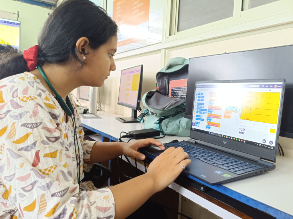
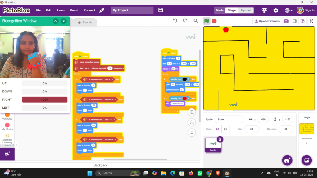
First, we need to choose the background for our project.
Then, we select the character that we want to use.
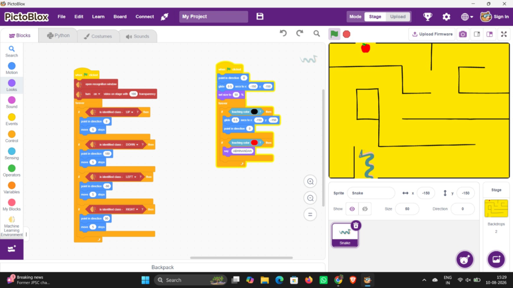
We built a simple puzzle game .
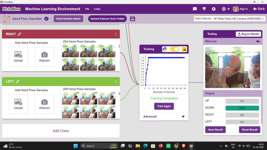
We kept the controlling on Hand Gestures
2. Processing

Processing is a software and programming language used to create graphics, animations, games, and interactive applications. It is simple to use and helps us create visual projects by writing code. We can use it to make different shapes, designs, buttons, animations, and other interactive elements.
Processing can also be used with Arduino to connect hardware with a computer application. In this type of project, we use two codes: one code is written in the Arduino IDE to control the Arduino and its components, and another code is written in Processing using Java to create the graphical interface and communicate with the Arduino.
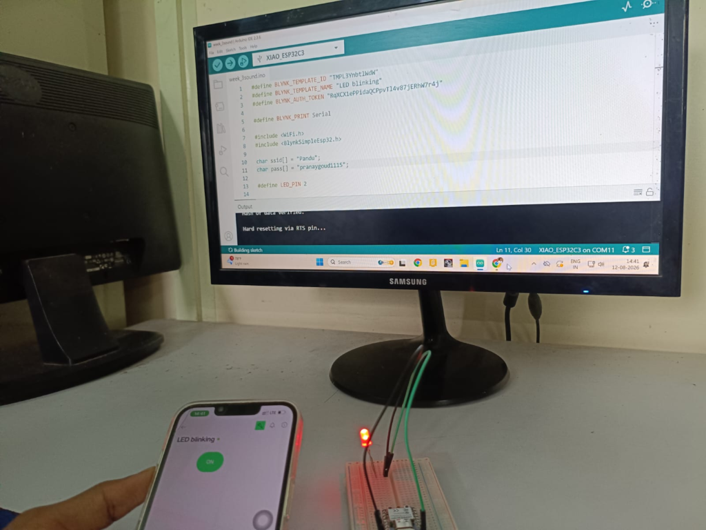
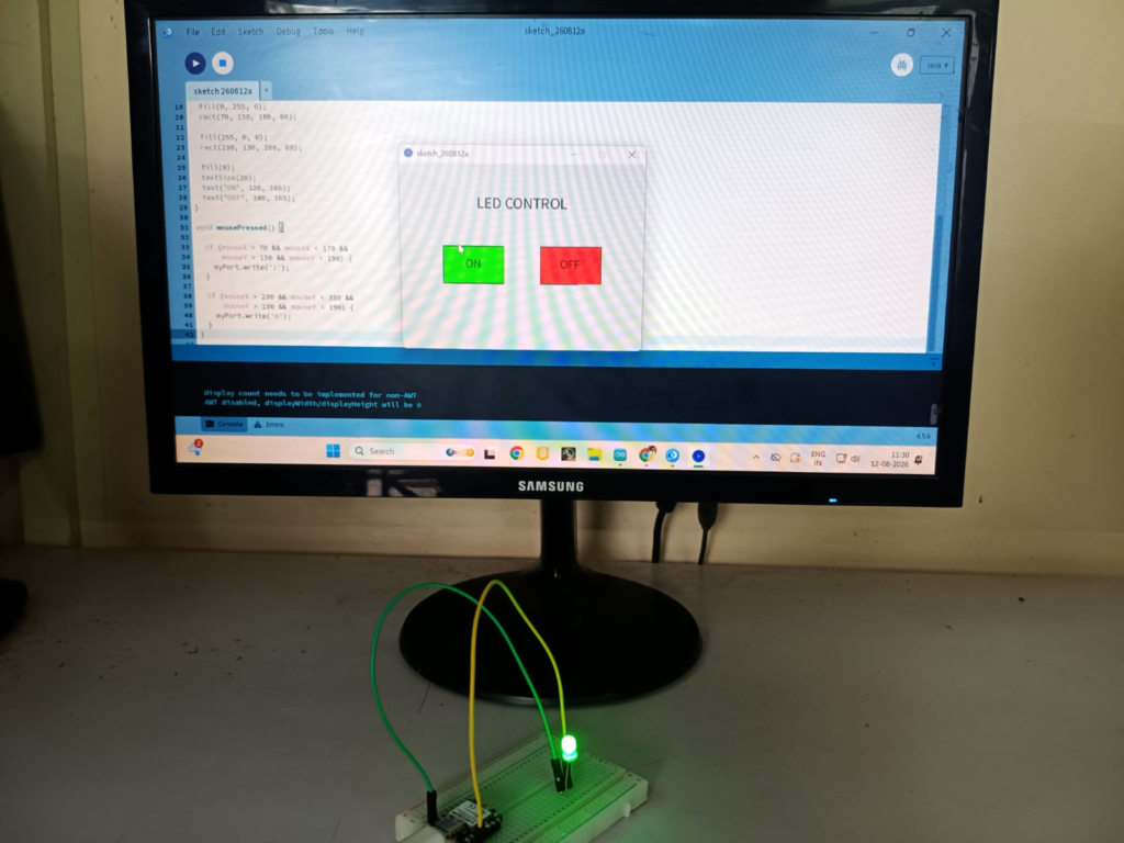
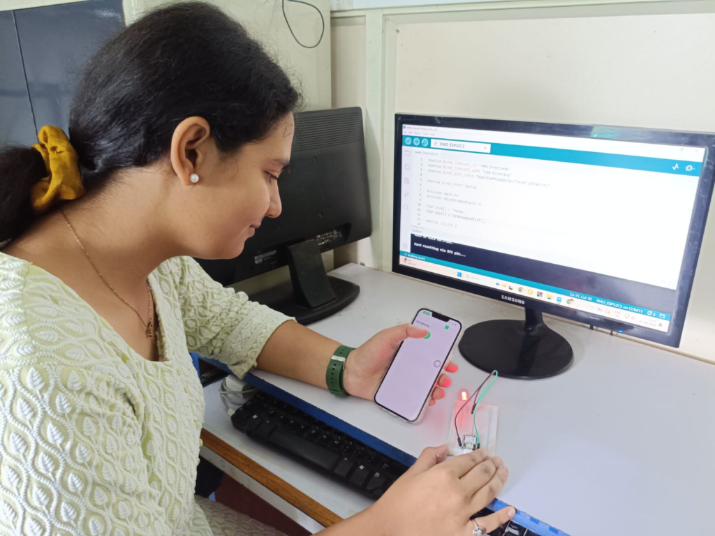
We blinked LED with Processing
At First we connected our Phone Network with XIAO ESP32C3 and removed IP Address
Then, In Ardunio ID I used this code
const int RED_PIN = 9;
const int GREEN_PIN = 8;
const int BLUE_PIN = 7;
void setup() {
pinMode(RED_PIN, OUTPUT);
pinMode(GREEN_PIN, OUTPUT);
pinMode(BLUE_PIN, OUTPUT);
Serial.begin(115200);
// RGB OFF
digitalWrite(RED_PIN, LOW);
digitalWrite(GREEN_PIN, LOW);
digitalWrite(BLUE_PIN, LOW);
}
void loop() {
if (Serial.available() > 0) {
char command = Serial.read();

if (command == 'R') {       // RED
  digitalWrite(RED_PIN, HIGH);
  digitalWrite(GREEN_PIN, LOW);
  digitalWrite(BLUE_PIN, LOW);
}

else if (command == 'G') {  // GREEN
  digitalWrite(RED_PIN, LOW);
  digitalWrite(GREEN_PIN, HIGH);
  digitalWrite(BLUE_PIN, LOW);
}

else if (command == 'B') {  // BLUE
  digitalWrite(RED_PIN, LOW);
  digitalWrite(GREEN_PIN, LOW);
  digitalWrite(BLUE_PIN, HIGH);
}

else if (command == 'Y') {  // YELLOW
  digitalWrite(RED_PIN, HIGH);
  digitalWrite(GREEN_PIN, HIGH);
  digitalWrite(BLUE_PIN, LOW);
}

else if (command == 'P') {  // PURPLE
  digitalWrite(RED_PIN, HIGH);
  digitalWrite(GREEN_PIN, LOW);
  digitalWrite(BLUE_PIN, HIGH);
}

else if (command == 'C') {  // CYAN
  digitalWrite(RED_PIN, LOW);
  digitalWrite(GREEN_PIN, HIGH);
  digitalWrite(BLUE_PIN, HIGH);
}

else if (command == 'W') {  // WHITE
  digitalWrite(RED_PIN, HIGH);
  digitalWrite(GREEN_PIN, HIGH);
  digitalWrite(BLUE_PIN, HIGH);
}

else if (command == '0') {  // OFF
  digitalWrite(RED_PIN, LOW);
  digitalWrite(GREEN_PIN, LOW);
  digitalWrite(BLUE_PIN, LOW);
}
Then, In Processing we used this code
const int RED_PIN = 9;
const int GREEN_PIN = 8;
const int BLUE_PIN = 7;

void setup() {
  pinMode(RED_PIN, OUTPUT);
  pinMode(GREEN_PIN, OUTPUT);
  pinMode(BLUE_PIN, OUTPUT);

  Serial.begin(115200);

  // RGB OFF
  digitalWrite(RED_PIN, LOW);
  digitalWrite(GREEN_PIN, LOW);
  digitalWrite(BLUE_PIN, LOW);
}

void loop() {
  if (Serial.available() > 0) {

    char command = Serial.read();

    if (command == 'R') {       // RED
      digitalWrite(RED_PIN, HIGH);
      digitalWrite(GREEN_PIN, LOW);
      digitalWrite(BLUE_PIN, LOW);
    }

    else if (command == 'G') {  // GREEN
      digitalWrite(RED_PIN, LOW);
      digitalWrite(GREEN_PIN, HIGH);
      digitalWrite(BLUE_PIN, LOW);
    }

    else if (command == 'B') {  // BLUE
      digitalWrite(RED_PIN, LOW);
      digitalWrite(GREEN_PIN, LOW);
      digitalWrite(BLUE_PIN, HIGH);
    }

    else if (command == 'Y') {  // YELLOW
      digitalWrite(RED_PIN, HIGH);
      digitalWrite(GREEN_PIN, HIGH);
      digitalWrite(BLUE_PIN, LOW);
    }

    else if (command == 'P') {  // PURPLE
      digitalWrite(RED_PIN, HIGH);
      digitalWrite(GREEN_PIN, LOW);
      digitalWrite(BLUE_PIN, HIGH);
    }

    else if (command == 'C') {  // CYAN
      digitalWrite(RED_PIN, LOW);
      digitalWrite(GREEN_PIN, HIGH);
      digitalWrite(BLUE_PIN, HIGH);
    }

    else if (command == 'W') {  // WHITE
      digitalWrite(RED_PIN, HIGH);
      digitalWrite(GREEN_PIN, HIGH);
      digitalWrite(BLUE_PIN, HIGH);
    }

    else if (command == '0') {  // OFF
      digitalWrite(RED_PIN, LOW);
      digitalWrite(GREEN_PIN, LOW);
      digitalWrite(BLUE_PIN, LOW);
    }
  }
}
3.Blockly
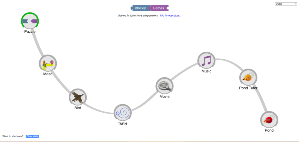
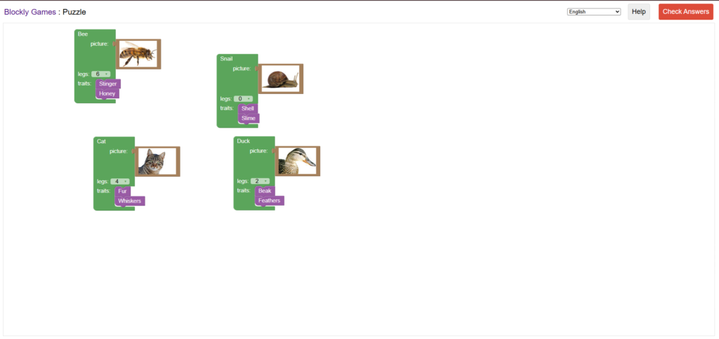
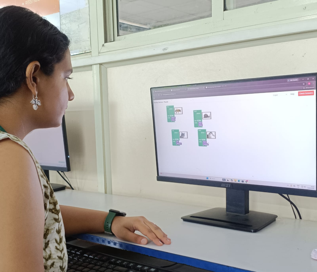
Blockly is a visual programming system that allows us to create programs using blocks instead of typing code. We can drag and connect different blocks to create instructions, making programming easier for beginners.
Blockly is used for learning programming, creating games, controlling robots, and working with electronics. Each block represents a command, such as moving a character, turning on an LED, or repeating an action. When the blocks are connected, they form a complete program.
4. P5.JS

p5.js is a simple and easy-to-use JavaScript library used to create creative and interactive projects. It allows us to create drawings, shapes, animations, games, and different visual effects using code. Instead of only displaying text on a webpage, p5.js helps us create things that we can see and interact with on the screen. It is especially useful for beginners because the commands are easy to understand and we can quickly see the result of our code.
p5.js is mainly used for creative coding and visual programming. We can use it to create circles, rectangles, lines, colors, moving objects, buttons, and animations. We can also make simple games and interactive applications where the user can click, move the mouse, or press keys to control what happens on the screen. This makes programming more interesting and easier to understand.
In simple words, p5.js helps us turn JavaScript code into visual and interactive projects. It is useful for learning programming, creating animations, designing interactive websites, and developing creative projects.
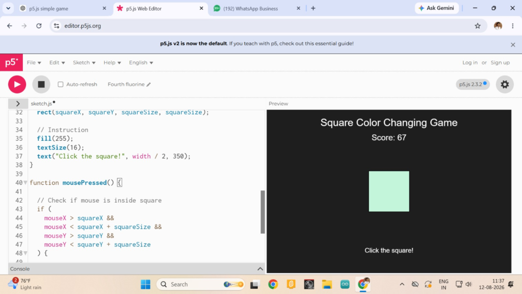
I Made different games using the Java Coding
throught this code I made game of sqaure changing game
This was the code I used
let x, y;
let squareSize = 80;
let score = 0;
let squareColor;

function setup() {
  createCanvas(500, 400);
  x = random(50, width - 50);
  y = random(50, height - 50);
  squareColor = color(random(255), random(255), random(255));
}

function draw() {
  background(220);

  // Title and score
  fill(0);
  textSize(24);
  text("Colour Changing Square Game", 100, 35);

  textSize(20);
  text("Score: " + score, 20, 70);

  // Square
  fill(squareColor);
  rect(x, y, squareSize, squareSize);
}

function mousePressed() {
  // Check if square is clicked
  if (
    mouseX > x &&
    mouseX < x + squareSize &&
    mouseY > y &&
    mouseY < y + squareSize
  ) {
    score++;

    // Change colour
    squareColor = color(
      random(255),
      random(255),
      random(255)
    );

    // Move square
    x = random(0, width - squareSize);
    y = random(80, height - squareSize);
  }
}
5.Web Server

A web server is a computer or device that stores, processes, and delivers web pages to users through a network or the internet. It receives requests from a web browser and sends the required webpage or data back to the browser. In an Arduino project, an ESP8266 or ESP32 can work as a web server. After connecting to Wi-Fi, the ESP gets an IP address. When this IP address is entered into a browser, a web interface created in the Arduino IDE appears. This interface can be used to control devices such as LEDs, relays, motors, or a smart bell.
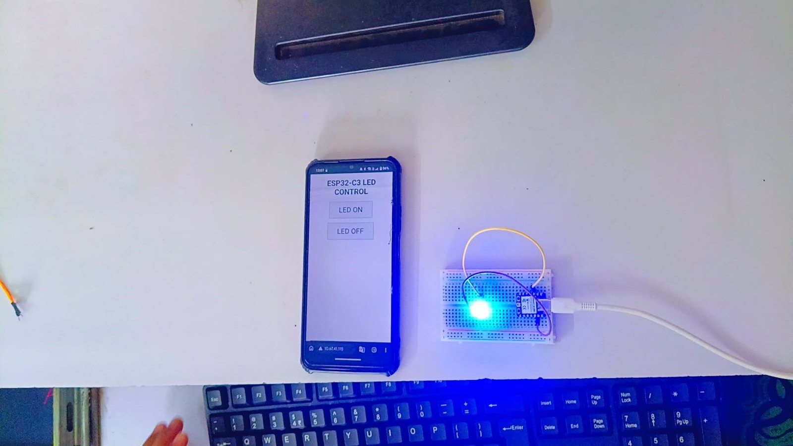
Developed an ESP32-C3 Web Server Based LED ON/OFF Control System
The ESP32-C3 web server LED control system allows us to control an LED wirelessly using a mobile phone or computer. The ESP32-C3 is connected to Wi-Fi and works as a web server. It provides an IP address, which is entered into a web browser to open the control interface. The interface has ON and OFF buttons. When the ON button is pressed, the ESP32-C3 turns the LED ON, and when the OFF button is pressed, it turns the LED OFF. This project demonstrates how an ESP32-C3 can be used to control electronic devices through a web server.
Code I used :-
#include <WiFi.h>
#include <WebServer.h>

const char* ssid = "YOUR_WIFI_NAME";
const char* password = "YOUR_WIFI_PASSWORD";

#define LED_PIN 4   // Change this GPIO if needed

WebServer server(80);

void handleRoot() {
  String html = "<!DOCTYPE html><html>";
  html += "<head><title>ESP32-C3 LED Control</title></head>";
  html += "<body style='text-align:center;'>";
  html += "<h1>ESP32-C3 LED Control</h1>";
  html += "<a href='/on'><button style='font-size:30px;'>ON</button></a>";
  html += "<br><br>";
  html += "<a href='/off'><button style='font-size:30px;'>OFF</button></a>";
  html += "</body></html>";

  server.send(200, "text/html", html);
}

void ledOn() {
  digitalWrite(LED_PIN, HIGH);
  server.sendHeader("Location", "/");
  server.send(303);
}

void ledOff() {
  digitalWrite(LED_PIN, LOW);
  server.sendHeader("Location", "/");
  server.send(303);
}

void setup() {
  Serial.begin(115200);

  pinMode(LED_PIN, OUTPUT);
  digitalWrite(LED_PIN, LOW);

  WiFi.begin(ssid, password);

  Serial.print("Connecting to WiFi");

  while (WiFi.status() != WL_CONNECTED) {
    delay(500);
    Serial.print(".");
  }

  Serial.println();
  Serial.println("WiFi Connected!");
  Serial.print("IP Address: ");
  Serial.println(WiFi.localIP());

  server.on("/", handleRoot);
  server.on("/on", ledOn);
  server.on("/off", ledOff);

  server.begin();

  Serial.println("Web Server Started");
}

void loop() {
  server.handleClient();
}
Application
Mit App inventor
What is Mit App Inventor?
What is MIT App Inventor?MIT App Inventor is a beginner-friendly online platform used to create mobile applications using block-based coding instead of writing complex programming code. It provides a Designer section for creating the app interface and a Blocks section for adding functions and actions.
Developing a Temperature and Humidity Monitoring System Using DHT11 and ESP32-C3
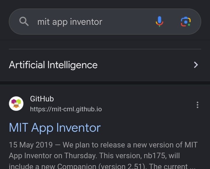
Step 1: Searching and Opening MIT App Inventor
First, I searched for MIT App Inventor in my web browser and opened the official MIT App Inventor website. After opening the platform, I created a new project for my DHT11 sensor project. MIT App Inventor allowed me to design a mobile app interface and create its functions using block coding.
Step 2: Setting Up the DHT11 Sensor
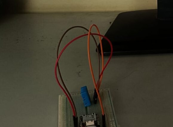
Next, I connected the DHT11 sensor to the ESP32-C3. I connected the DATA pin of the DHT11 to GPIO 2, along with the required 5V and GND connections. The sensor is used to measure temperature and humidity.
Step 3: Designing the App Interface
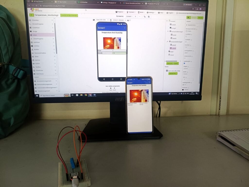
After setting up the sensor, I designed the mobile app interface in MIT App Inventor. I added the required components to display the temperature and humidity readings. I arranged the interface so that the sensor values could be viewed clearly on the mobile screen.
Step 4: Adding Block Coding
Next, I opened the Blocks section in MIT App Inventor and created the block code for my application. The blocks were used to receive and display the temperature and humidity data from the ESP32-C3. I connected the blocks according to the required logic so that the readings could be shown in the app.
Step 5: Testing and Final Result
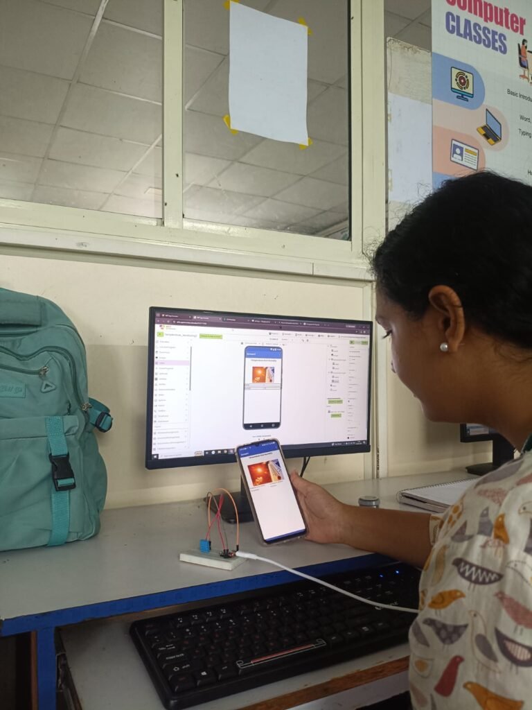
Finally, I tested the complete project by running the MIT App Inventor application and checking the DHT11 readings. The ESP32-C3 collected the temperature and humidity data, and the values were displayed in the mobile app. After testing the system, I successfully created a DHT11 temperature and humidity monitoring application using MIT App Inventor and ESP32-C3
Blynk

Developing a DHT22 Monitoring System Using Blynk App and ESP32-C3
Step 1: Opening the Blynk App
First, I opened the Blynk IoT platform and created a new project for my temperature and humidity monitoring system. I prepared the Blynk app so that the ESP32-C3 could send the sensor readings to my mobile phone.
Step 2: Connecting the DHT22 Sensor
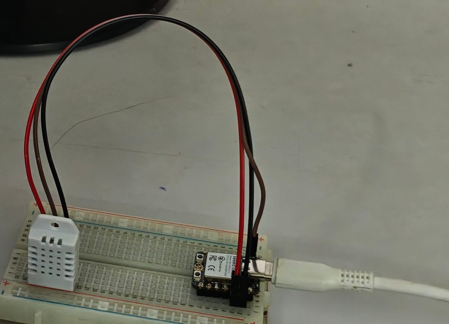
Next, I connected the DHT22 temperature and humidity sensor to the ESP32-C3 on a breadboard. I connected the DATA pin of the DHT22 to the required GPIO pin of the ESP32-C3 and also connected the power and GND wires correctly. The DHT22 is used to measure both temperature and humidity
Step 3: Writing and Uploading the CodeAfter
Completing the circuit, I opened the Arduino IDE and wrote the code for the ESP32-C3, DHT22, and Blynk. The program connects the ESP32-C3 to Wi-Fi, reads the temperature and humidity values from the DHT22, and sends the readings to the Blynk app. After completing the code, I uploaded it to the ESP32-C3.
Step 4: Creating the Blynk Interface
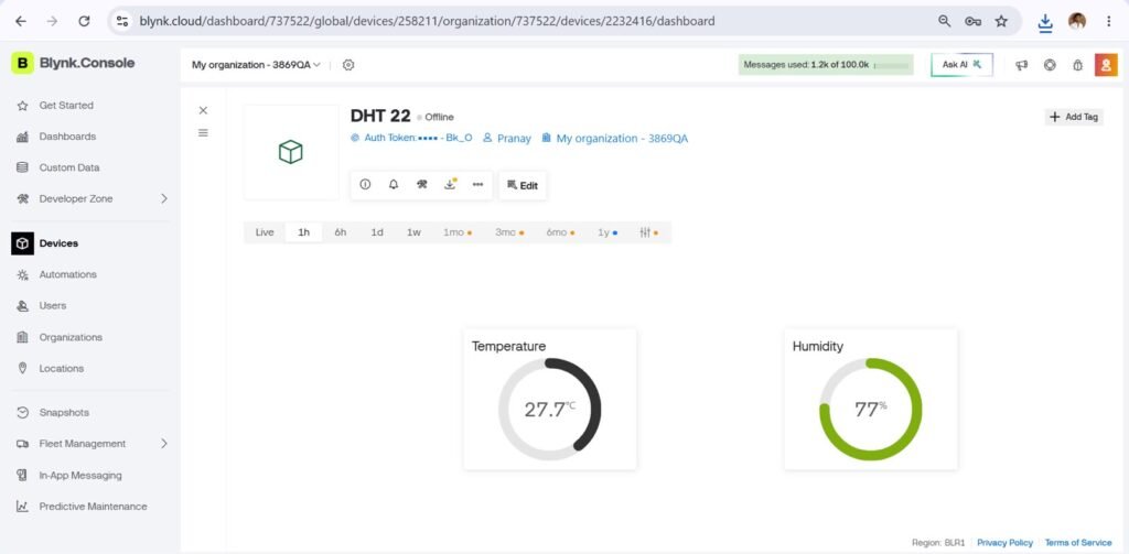
After uploading the code, I created the Blynk mobile interface to display the DHT22 readings. I added widgets to show the temperature and humidity values. Once the ESP32-C3 connected to Blynk, the sensor readings were displayed on my phone
Step 5: Testing and Final Result
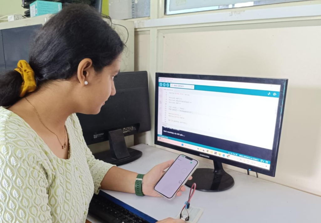
Finally, I tested the complete system by checking the temperature and humidity values shown in the Blynk app. The DHT22 sensor measured the temperature and humidity, and the ESP32-C3 sent the data to the Blynk app through Wi-Fi. In my final result, the mobile app displayed the sensor readings successfully.
Code I use for this-
#define BLYNK_TEMPLATE_ID "YOUR_TEMPLATE_ID"
#define BLYNK_TEMPLATE_NAME "DHT22"
#define BLYNK_AUTH_TOKEN "YOUR_BLYNK_AUTH_TOKEN"

#define BLYNK_PRINT Serial

#include <WiFi.h>
#include <BlynkSimpleEsp32.h>
#include <DHT.h>

// Wi-Fi details
char ssid[] = "Pandu";
char pass[] = "pranaygoud1115";

// DHT22 connection
#define DHTPIN 2
#define DHTTYPE DHT22

DHT dht(DHTPIN, DHTTYPE);

BlynkTimer timer;

void sendSensorData()
{
  float temperature = dht.readTemperature();
  float humidity = dht.readHumidity();

  if (isnan(temperature) || isnan(humidity))
  {
    Serial.println("DHT22 sensor reading failed!");
    return;
  }

  // Serial Monitor
  Serial.print("Temperature: ");
  Serial.print(temperature);
  Serial.println(" °C");

  Serial.print("Humidity: ");
  Serial.print(humidity);
  Serial.println(" %");

  // Send data to Blynk
  Blynk.virtualWrite(V0, temperature);
  Blynk.virtualWrite(V1, humidity);
}

void setup()
{
  Serial.begin(115200);

  dht.begin();

  // Connect ESP32-C3 to Wi-Fi and Blynk
  Blynk.begin(BLYNK_AUTH_TOKEN, ssid, pass);

  // Read sensor every 2 seconds
  timer.setInterval(2000L, sendSensorData);
}

void loop()
{
  Blynk.run();
  timer.run();
}