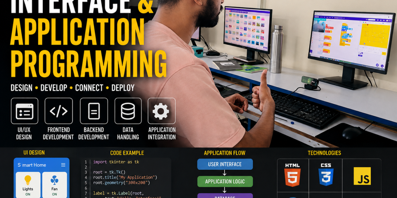
Introduction
This week, I learned to develop applications using MIT App Inventor and Blynk. I created apps on both platforms and used them to control a microcontroller and make an LED blink.
I also worked with Processing and web servers to turn the LED ON and OFF. In Blockly, I practiced block-based coding, and in Pictoblocks, I created a game. This week improved my understanding of programming, app development, and hardware control.
Individual assignment
In this individual assignment, I developed and tested different application interfaces to communicate with and control a microcontroller board. The main objective was to understand how microcontroller hardware can be controlled using different software tools and application development platforms. I explored MIT App Inventor, Processing, Blynk, Web Server, PictoBlox, p5.js, and Blockly and compared their features, communication methods, and ease of use.
PictoBlox

What is PictoBlox?
PictoBlox is a beginner-friendly coding platform that makes learning programming fun and interactive. It uses colorful block-based coding, so you can create programs by simply dragging and connecting blocks instead of typing complicated code. With PictoBlox, you can create animations, stories, games, and many other exciting projects. It is especially useful for students who are learning the basics of programming and want to turn their ideas into interactive projects.
Designing the Game Interface

I started by designing the interface of my game in PictoBlox. I created a maze with a bright yellow background and added walls to form different paths. I also added a beetle as the main character and an apple as the target. The aim of the game is to guide the beetle through the maze while avoiding the walls and reaching the target.
Adding Hand Gesture Controls
After designing the interface, I used the Machine Learning features available in PictoBlox to make my game more interactive. I used the Hand Pose Classifier to recognize different hand gestures. I set up gestures such as Forward, Backward, Left, and Right, which allow me to control the movement of the beetle without using a keyboard.
Adding the Block Code.

Next, I created the block code that connects the hand gestures to the beetle’s movements. When PictoBlox identifies a particular gesture, the beetle moves in the corresponding direction. I also added code to detect when the beetle touches the maze walls and return it to its previous position. This made the game more challenging and interactive
Testing and Improving the Game

Finally, I tested my game several times to make sure the hand gestures and beetle movements worked correctly. I checked whether the beetle moved forward, backward, left, and right as expected. I also tested the wall detection and made changes wherever necessary. After completing the testing and improvements, I was able to create a working hand-gesture-controlled maze game in PictoBlox.
Processing Software

What is Processing?
Processing is a programming software and creative coding platform used to create interactive graphics, animations, visual applications, and interfaces. It uses a simple programming language that makes it easier for beginners to learn coding and create projects.
Developed an RGB LED Control System Using Processing Software
Downloading and Installing Processing
First, I downloaded the Processing software from the official Processing website. Processing is available for Windows, macOS, Linux. After downloading the suitable version for my computer, I installed it and opened the Processing software. This was the first step because I needed Processing to create the control interface for my RGB LED project.


Setting Up the RGB LED
After installing Processing, I set up the RGB LED with the ESP32-C3 on a breadboard. I connected the three color channels of the RGB LED to different GPIO pins of the ESP32-C3. In my project, the Red (R) channel is connected to GPIO 9, the Green (G) channel is connected to GPIO 8, and the Blue (B) channel is connected to GPIO 7. I also made the required power and ground connections and checked the circuit carefully before starting the programming.

Writing the Code in Arduino IDE
Next, I created the first program in the Arduino IDE. This code is responsible for controlling the RGB LED through the ESP32-C3. I used the three GPIO pins to control the red, green, and blue components of the LED. The Arduino code also allows the ESP32-C3 to receive commands from the computer. After completing the code, I selected the correct ESP32-C3 board and port.

Opening Processing and Writing the Program
After preparing the Arduino code, I opened the downloaded Processing software on my computer. Once Processing was opened, I created a new program and wrote the second code for my RGB LED project. This program was designed to create the control interface and communicate with the ESP32-C3. After writing the Processing program, I checked the code and prepared it to work with the ESP32-C3 and control the RGB LED.

Uploading and Running the Processing Code
After uploading the ESP32-C3 code through the Arduino IDE, I opened the Processing Software and added my Processing code. When I ran the code, the RGB LED Control interface automatically appeared in a separate window. The interface contains buttons for RED, GREEN, BLUE, YELLOW, PURPLE, CYAN, and OFF, which I designed to control the RGB LED through the ESP32-C3.

Testing the Final Result
After the interface appeared, I tested each button to check whether the RGB LED responded correctly. I clicked different color buttons, and the LED changed to the selected color. I also tested the OFF button to turn the LED off. The successful response showed that my Processing program was communicating correctly with the ESP32-C3 and controlling the RGB LED as expected.

Code I use for my project :-
For Arduino IDE
const int RED_PIN = 9;
const int GREEN_PIN = 8;
const int BLUE_PIN = 7;

void setup() {
  pinMode(RED_PIN, OUTPUT);
  pinMode(GREEN_PIN, OUTPUT);
  pinMode(BLUE_PIN, OUTPUT);

  Serial.begin(115200);

  // RGB OFF
  digitalWrite(RED_PIN, LOW);
  digitalWrite(GREEN_PIN, LOW);
  digitalWrite(BLUE_PIN, LOW);
}

void loop() {
  if (Serial.available() > 0) {

    char command = Serial.read();

    if (command == 'R') {       // RED
      digitalWrite(RED_PIN, HIGH);
      digitalWrite(GREEN_PIN, LOW);
      digitalWrite(BLUE_PIN, LOW);
    }

    else if (command == 'G') {  // GREEN
      digitalWrite(RED_PIN, LOW);
      digitalWrite(GREEN_PIN, HIGH);
      digitalWrite(BLUE_PIN, LOW);
    }

    else if (command == 'B') {  // BLUE
      digitalWrite(RED_PIN, LOW);
      digitalWrite(GREEN_PIN, LOW);
      digitalWrite(BLUE_PIN, HIGH);
    }

    else if (command == 'Y') {  // YELLOW
      digitalWrite(RED_PIN, HIGH);
      digitalWrite(GREEN_PIN, HIGH);
      digitalWrite(BLUE_PIN, LOW);
    }

    else if (command == 'P') {  // PURPLE
      digitalWrite(RED_PIN, HIGH);
      digitalWrite(GREEN_PIN, LOW);
      digitalWrite(BLUE_PIN, HIGH);
    }

    else if (command == 'C') {  // CYAN
      digitalWrite(RED_PIN, LOW);
      digitalWrite(GREEN_PIN, HIGH);
      digitalWrite(BLUE_PIN, HIGH);
    }

    else if (command == 'W') {  // WHITE
      digitalWrite(RED_PIN, HIGH);
      digitalWrite(GREEN_PIN, HIGH);
      digitalWrite(BLUE_PIN, HIGH);
    }

    else if (command == '0') {  // OFF
      digitalWrite(RED_PIN, LOW);
      digitalWrite(GREEN_PIN, LOW);
      digitalWrite(BLUE_PIN, LOW);
    }
  }
}
For Processing code
import processing.serial.*;

Serial myPort;

void setup() {
  size(600, 500);

  // ESP32-C3 is on COM19
  myPort = new Serial(this, "COM19", 115200);
}

void draw() {
  background(40);

  // Title
  fill(255);
  textAlign(CENTER);
  textSize(30);
  text("RGB LED CONTROL", width/2, 50);

  // RED button
  fill(255, 0, 0);
  rect(50, 100, 220, 70, 15);

  fill(255);
  textSize(22);
  text("RED", 160, 143);

  // GREEN button
  fill(0, 200, 0);
  rect(330, 100, 220, 70, 15);

  fill(255);
  text("GREEN", 440, 143);

  // BLUE button
  fill(0, 100, 255);
  rect(50, 200, 220, 70, 15);

  fill(255);
  text("BLUE", 160, 243);

  // YELLOW button
  fill(255, 220, 0);
  rect(330, 200, 220, 70, 15);

  fill(0);
  text("YELLOW", 440, 243);

  // PURPLE button
  fill(180, 0, 255);
  rect(50, 300, 220, 70, 15);

  fill(255);
  text("PURPLE", 160, 343);

  // CYAN button
  fill(0, 220, 220);
  rect(330, 300, 220, 70, 15);

  fill(0);
  text("CYAN", 440, 343);

  // OFF button
  fill(100);
  rect(200, 400, 200, 60, 15);

  fill(255);
  text("OFF", 300, 438);
}

void mousePressed() {

  // RED
  if (mouseX > 50 && mouseX < 270 &&
      mouseY > 100 && mouseY < 170) {
    myPort.write('R');
  }

  // GREEN
  else if (mouseX > 330 && mouseX < 550 &&
           mouseY > 100 && mouseY < 170) {
    myPort.write('G');
  }

  // BLUE
  else if (mouseX > 50 && mouseX < 270 &&
           mouseY > 200 && mouseY < 270) {
    myPort.write('B');
  }

  // YELLOW
  else if (mouseX > 330 && mouseX < 550 &&
           mouseY > 200 && mouseY < 270) {
    myPort.write('Y');
  }

  // PURPLE
  else if (mouseX > 50 && mouseX < 270 &&
           mouseY > 300 && mouseY < 370) {
    myPort.write('P');
  }

  // CYAN
  else if (mouseX > 330 && mouseX < 550 &&
           mouseY > 300 && mouseY < 370) {
    myPort.write('C');
  }

  // OFF
  else if (mouseX > 200 && mouseX < 400 &&
           mouseY > 400 && mouseY < 460) {
    myPort.write('0');
  }
}
Web Server

Developing an LED Control System Using On Web Server
Writing the Code in Arduino IDE
First, I opened the Arduino IDE and wrote the web server code for the ESP32-C3. In the code, I programmed the ESP32-C3 to connect to a Wi-Fi network and control the LED. The program also creates a web server that provides an interface for controlling the LED.

Connecting the ESP32-C3 to Wi-Fi
After writing the code, I uploaded it to the ESP32-C3. Once the program started running, the ESP32-C3 connected to the specified Wi-Fi network. After connecting successfully, the ESP32-C3 generated an IP address. I noted this IP address because it is used to access the web server.
Opening the IP Address in Chrome
Next, I opened Google Chrome on my computer or phone and entered the ESP32-C3 IP address in the address bar with http:// before it. For example, if the IP address is 192.168.1.100, I entered:
http://192.168.1.100After entering the address and pressing Enter, the browser connected to the ESP32-C3 web server.

Using the Web Interface
After opening the IP address, the LED control interface automatically appeared in the browser. The interface contained buttons such as LED ON and LED OFF. I could use these buttons to send commands to the ESP32-C3 and control the connected LED.

Testing the LED and Final Result
Finally, I tested the web interface by pressing the LED ON and LED OFF buttons. When I selected LED ON, the ESP32-C3 received the command and the LED turned on. Similarly, selecting LED OFF turned the LED off. This showed that the ESP32-C3 web server was successfully communicating with the LED through the browser.

Code I use for my project :-
#include <WiFi.h>
#include <WebServer.h>

const char* ssid = "Redmi 12 5G";
const char* password = "123456789";

WebServer server(80);

#define LED_PIN 4

bool ledState = false;

// Web page
void handleRoot() {

  String page = "<!DOCTYPE html>";
  page += "<html>";
  page += "<head>";
  page += "<meta name='viewport' content='width=device-width, initial-scale=1'>";
  page += "<title>ESP32-C3 LED Control</title>";
  page += "</head>";

  page += "<body style='text-align:center;font-family:Arial;'>";
  page += "<h1>ESP32-C3 LED Control</h1>";

  page += "<h2>LED: ";
  page += ledState ? "ON" : "OFF";
  page += "</h2>";

  page += "<br>";

  page += "<a href='/on'>";
  page += "<button style='font-size:25px;padding:15px 30px;'>LED ON</button>";
  page += "</a>";

  page += "<br><br>";

  page += "<a href='/off'>";
  page += "<button style='font-size:25px;padding:15px 30px;'>LED OFF</button>";
  page += "</a>";

  page += "</body>";
  page += "</html>";

  server.send(200, "text/html", page);
}

// LED ON
void ledOn() {

  digitalWrite(LED_PIN, HIGH);
  ledState = true;

  server.sendHeader("Location", "/");
  server.send(303);
}

// LED OFF
void ledOff() {

  digitalWrite(LED_PIN, LOW);
  ledState = false;

  server.sendHeader("Location", "/");
  server.send(303);
}

void setup() {

  Serial.begin(115200);

  // LED
  pinMode(LED_PIN, OUTPUT);
  digitalWrite(LED_PIN, LOW);

  // Connect to Wi-Fi
  WiFi.begin(ssid, password);

  Serial.print("Connecting to Wi-Fi");

  while (WiFi.status() != WL_CONNECTED) {
    delay(500);
    Serial.print(".");
  }

  Serial.println();
  Serial.println("Wi-Fi Connected!");

  Serial.print("ESP32-C3 IP Address: ");
  Serial.println(WiFi.localIP());

  // Web server
  server.on("/", handleRoot);
  server.on("/on", ledOn);
  server.on("/off", ledOff);

  server.begin();

  Serial.println("Web Server Started!");
}

void loop() {

  server.handleClient();
}
p5.js Web Editor

What is p5.js Web Editor?
The p5.js Web Editor is an online coding platform where you can write, run, and test programs using p5.js, a JavaScript library designed for creative coding. It allows you to create games, animations, interactive graphics, and other visual projects directly in a web browser.
The editor is beginner-friendly because you can write your code on one side and see the result in the preview window. In my project, I used the p5.js Web Editor to write my game code, run it, and play the game directly in the browser.
Got it. p5.js Web Editor is only for your game—there is no LED or ESP32-C3 in this project. You simply open the p5.js Web Editor, enter the game code, run it, and play the game.
Developing a Game Using p5.js Web Editor
Opening the p5.js Web Editor
First, I searched for p5.js Web Editor in my web browser and opened the official editor. The p5.js Web Editor provides an online space where I can write, run, and test my game code without installing any additional software.

Writing the Game Code
After opening the p5.js Web Editor, I entered my game code into the editor. The code contains the instructions for the game’s characters, movements, objects, background, and other features. I organized the code carefully so that all the different parts of the game would work together.

Running the Game
Once I finished writing the code, I clicked the Run/Play button in the p5.js Web Editor. The editor automatically generated the game in the preview area. I could see my game running directly in the browser and check whether the characters and other elements were working correctly.

Playing and Testing the Game
Finally, I played the game directly in the p5.js Web Editor. I tested the controls, movement, and different game features to make sure everything worked properly. If I found any mistakes, I went back to the code, made changes, and ran the game again. After testing and improving the code, my game was ready to play.

Code I use for my project :-
let car;
let obstacles = [];
let score = 0;
let gameOver = false;

function setup() {
  createCanvas(600, 600);
  car = {
    x: width / 2,
    y: height - 100,
    w: 45,
    h: 75,
    speed: 7
  };
}

function draw() {
  background(80, 80, 80);

  // Road
  fill(40);
  rect(80, 0, 440, height);

  // Road lines
  stroke(255);
  strokeWeight(5);
  for (let y = -40; y < height; y += 80) {
    line(width / 2, y + (frameCount * 6) % 80, width / 2, y + 40 + (frameCount * 6) % 80);
  }
  noStroke();

  // Grass
  fill(50, 150, 50);
  rect(0, 0, 80, height);
  rect(520, 0, 80, height);

  if (!gameOver) {
    moveCar();
    createObstacles();
    updateObstacles();
    checkCollisions();

    score += 0.02;
  }

  drawCar();

  // Score
  fill(255);
  textSize(24);
  text("Score: " + floor(score), 20, 35);

  if (gameOver) {
    fill(0, 0, 0, 180);
    rect(0, 0, width, height);

    fill(255, 50, 50);
    textAlign(CENTER);
    textSize(50);
    text("GAME OVER", width / 2, height / 2 - 30);

    fill(255);
    textSize(24);
    text("Press R to restart", width / 2, height / 2 + 30);
    textAlign(LEFT);
  }
}

function moveCar() {
  if (keyIsDown(LEFT_ARROW) || keyIsDown(65)) {
    car.x -= car.speed;
  }

  if (keyIsDown(RIGHT_ARROW) || keyIsDown(68)) {
    car.x += car.speed;
  }

  car.x = constrain(car.x, 105, 495);
}

function drawCar() {
  // Car body
  fill(220, 30, 30);
  rectMode(CENTER);
  rect(car.x, car.y, car.w, car.h, 8);

  // Windows
  fill(100, 200, 255);
  rect(car.x, car.y - 18, 32, 20, 5);
  rect(car.x, car.y + 18, 32, 15, 5);

  // Wheels
  fill(20);
  rect(car.x - 25, car.y - 25, 10, 22, 3);
  rect(car.x + 25, car.y - 25, 10, 22, 3);
  rect(car.x - 25, car.y + 25, 10, 22, 3);
  rect(car.x + 25, car.y + 25, 10, 22, 3);

  rectMode(CORNER);
}

function createObstacles() {
  if (frameCount % 45 === 0) {
    let x = random(110, 450);

    obstacles.push({
      x: x,
      y: -60,
      w: 45,
      h: 70,
      speed: random(4, 8)
    });
  }
}

function updateObstacles() {
  for (let i = obstacles.length - 1; i >= 0; i--) {
    let o = obstacles[i];

    o.y += o.speed;

    // Draw obstacle
    fill(30, 80, 220);
    rect(o.x, o.y, o.w, o.h, 8);

    fill(150, 220, 255);
    rect(o.x + 7, o.y + 10, o.w - 14, 18, 4);

    if (o.y > height + 80) {
      obstacles.splice(i, 1);
    }
  }
}

function checkCollisions() {
  for (let o of obstacles) {
    if (
      car.x - car.w / 2 < o.x + o.w / 2 &&
      car.x + car.w / 2 > o.x - o.w / 2 &&
      car.y - car.h / 2 < o.y + o.h / 2 &&
      car.y + car.h / 2 > o.y - o.h / 2
    ) {
      gameOver = true;
    }
  }
}

function keyPressed() {
  if ((key === "r" || key === "R") && gameOver) {
    obstacles = [];
    score = 0;
    gameOver = false;
    car.x = width / 2;
  }
}
Blockly Games Maze:

What is Blockly ?
Blockly Games Maze is a fun and beginner-friendly coding game that teaches programming through maze challenges. Players use visual blocks like move, turn, repeat, and if to guide a character through the maze. It helps beginners understand basic coding concepts such as logic, loops, conditions, and problem-solving without needing to write complex code.
How I Solved Blockly Games: Maze
Searching for Blockly Games: Maze
First, I opened my browser and searched for “Blockly Games: Maze.” I found the Blockly Games Maze website in the search results and clicked on it to open the game.

Opening the Maze Game
After clicking on the Blockly Games Maze website, the game opened on my screen. I could see a maze with a character and a destination point. My task was to guide the character from the starting position to the destination. I also saw different programming blocks that could be used to control the character and solve the maze.

Using the Coding Blocks
Next, I started using the available coding blocks to give instructions to the character. I dragged blocks such as Move Forward, Turn Left, and Turn Right and connected them in the correct order. I had to think carefully about the path before arranging the blocks because each block controlled the character’s movement in the maze.

Running and Testing the Code
After arranging the coding blocks, I clicked the Run button to test my instructions. The character started moving according to the blocks I had selected. If the character moved in the wrong direction or did not reach the destination, I changed the blocks and tried again. This helped me understand that programming often requires testing and correcting mistakes.

Solving the Maze
Finally, after arranging the correct sequence of blocks, I successfully guided the character to the destination and solved the maze. This activity helped me understand basic programming concepts such as instructions, sequence, logic, and problem-solving. Blockly Games Maze made learning coding more interesting because I could immediately see the result of the instructions I created.

Application
MIT App Inventor
MIT App Inventor is a web-based platform used to create mobile applications easily without requiring advanced programming skills. It uses a block-based programming approach, allowing users to design app interfaces and add functionality through visual blocks. It supports hardware communication using components like Bluetooth, enabling apps to control external devices such as Arduino boards. MIT App Inventor is widely used for developing simple Android applications, IoT projects, and automation-based systems.
What is MIT App Inventor
MIT App Inventor is a user-friendly, web-based platform developed by the Massachusetts Institute of Technology (MIT) for creating Android applications. It uses a visual programming method with drag-and-drop components and block-based coding, making app development easier for beginners. It allows users to design interfaces, add functions, and connect mobile applications with external hardware using communication methods like Bluetooth and Wi-Fi. It is widely used for educational projects, IoT applications, and automation systems.

The process I followed is as follows:-

First, I searched for MIT App Inventor and clicked on it.

Then , click on the Create App.

Ater that , Click on the Continue button.

After that, I selected “New Project”

Then, I entered the project .

Then, opened the project, and started creating the app.

First, I selected a Label and customized it. I also gave it a suitable name.

First, I selected the Image lable, and then I uploaded a photo to it.

Then, I selected two buttons for turning the LED ON and OFF. Finally, I completed the interface of the app.

Then, I do block coding to program the operations of the app.

Then, I go to the Build option, clicked on it, and selected Android APK to build the app.

Then, click on apk download it and open and download in mobile this file

Finally, the app was completed and worked successfully. The ON and OFF buttons controlled the LED properly.

Blynk App

What is Blynk?
Blynk is an IoT platform that helps you connect and control electronic devices using a mobile app or web dashboard. It can be used with boards like Arduino, ESP32 to control devices such as LEDs, motors, sensors, and relays over the internet.
For example, you can use the Blynk app on your phone to turn an LED ON or OFF on your ESP32 board. It is popular for learning and building smart home and IoT projects.
The process I followed is as follows:-

First, I opened the Blynk app. and Clicked on Get Started.

Then I sign Up the Emai.

After the interface appears, click on Developer Mode.

Click Create New Template, enter the name LED Blinking, select ESP as the hardware, and select WiFi as the connection typ

Copy the Template Name and Template ID, then save them for later use.

Click New Device, select the LED Blinking template, enter the Device Name, and then click Create.

Click on Edit Dashboard to customize the dashboard for the LED Blinking device

Select the Button widget, then click on Button to add it to the dashboard

Open the code in Arduino IDE, select the correct ESP board and COM port, and click Upload to upload the code to the ESP board.

After uploading the code to the ESP board, return to the Blynk dashboard and select the Virtual Pin Datastream for the button. The dashboard interface is now complete and ready to control the LED ON and OFF.


Open the Blynk mobile app and test the button. The LED turns ON and OFF successfully when the button is pressed.