Problem Statement
Farmers often have difficulty continuously monitoring the health of cows, especially when managing multiple animals. Manual checking of temperature and pulse rate requires time and regular observation. Early changes in these parameters may be missed during routine farm work. Therefore, there is a need for a simple, low-cost wearable system that can measure and display a cow’s body temperature and pulse rate, helping farmers observe basic health-related changes more easily
Proposed Solution
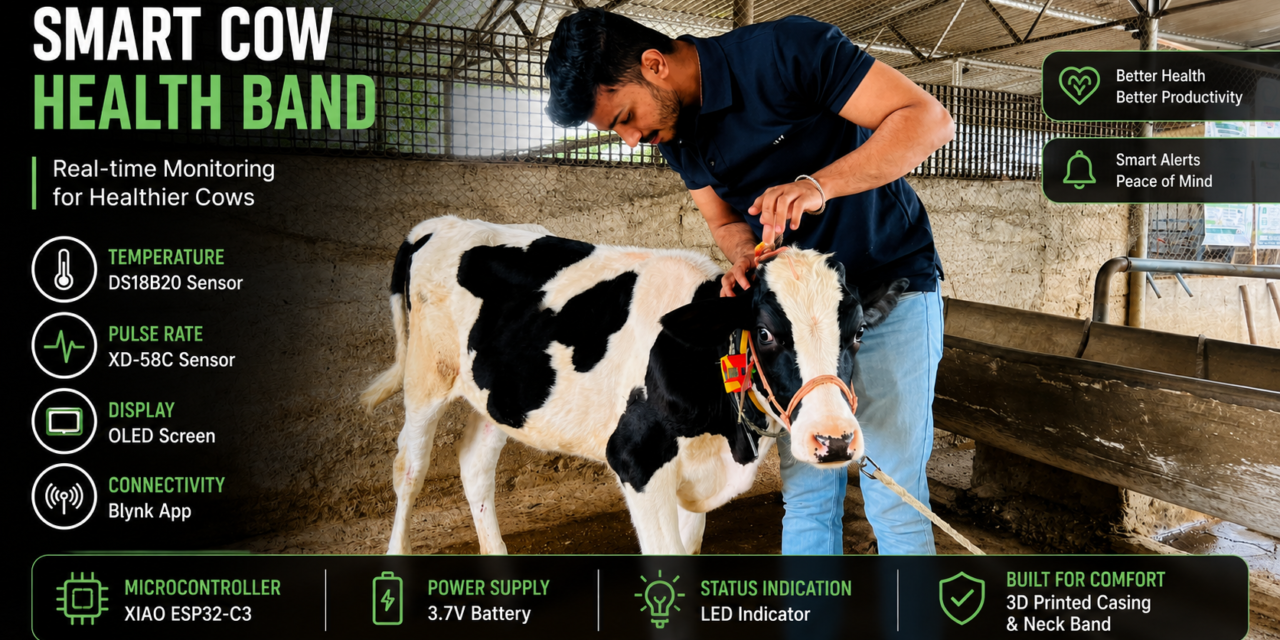
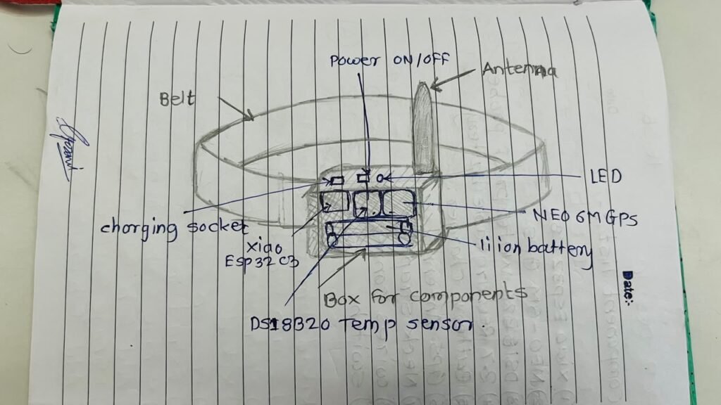
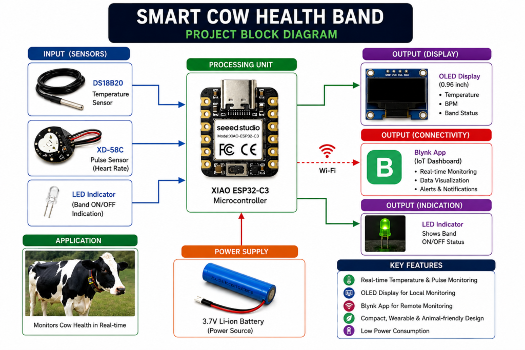
We developed a Smart Cow Health Band to make basic health monitoring of cows easier. The band uses a XIAO ESP32-C3 with a DS18B20 temperature sensor and an XD-58C pulse sensor to measure the cow’s temperature and pulse rate. The readings are processed by the controller and shown on an OLED display. An LED shows that the band is switched on and working.
The main aim of this project is to give farmers an easy way to check these basic health readings without having to measure them manually every time.
Design Planning and Component Selection
In the initial design plan, the project was developed with a DS18B20 temperature sensor and NEO-6M GPS module for monitoring the cow’s temperature and location. During the practical testing phase, the NEO-6M GPS module did not provide reliable results with the selected setup. Therefore, the design was modified by removing the GPS module and replacing it with an XD-58C pulse sensor. The final design focuses on monitoring the cow’s body temperature and pulse rate using the DS18B20 and XD-58C sensors, with an OLED display for local monitoring and an LED for system status indication.
Working Principle
The XIAO ESP32-C3 is the main controller of the system.
The DS18B20 temperature sensor measures the cow’s temperature and sends the temperature data to the ESP32-C3.
The XD-58C pulse sensor detects the pulse signal and the controller processes the signal to calculate the approximate BPM (beats per minute).
The measured temperature and pulse rate are displayed on the OLED display. The LED provides a simple indication that the monitoring band is switched ON.
Basic working flow
Cow → Sensors → XIAO ESP32-C3 → Data Processing → OLED Display
Block Diagram
Circuit / System Design
The circuit is built around the XIAO ESP32-C3, which acts as the main controller of the Smart Cow Health Band. The DS18B20 is connected to D2 to measure temperature, while the XD-58C pulse sensor is connected to D0 to measure the pulse signal. The OLED display uses I²C communication through D4 (SDA) and D5 (SCL) to show the readings.
An LED is connected to D10 to indicate that the band is powered and working. The sensors and OLED are powered from the 3.3V supply of the XIAO ESP32-C3, with all components sharing a common GND. A 4.7 kΩ pull-up resistor is connected between the DS18B20 data line and 3.3V.
Pin Connections
| Component | XIAO ESP32-C3 |
|---|---|
| DS18B20 DATA | D2 |
| XD-58C Signal | D0 |
| OLED SDA | D4 |
| OLED SCL | D5 |
| LED | D10 |
| Sensors/OLED VCC | 3.3V |
| Sensors/OLED GND | GND |
Components Used
For the Smart Cow Health Band, I used the following components:
- XIAO ESP32-C3 – Main microcontroller that reads the sensors and controls the system.
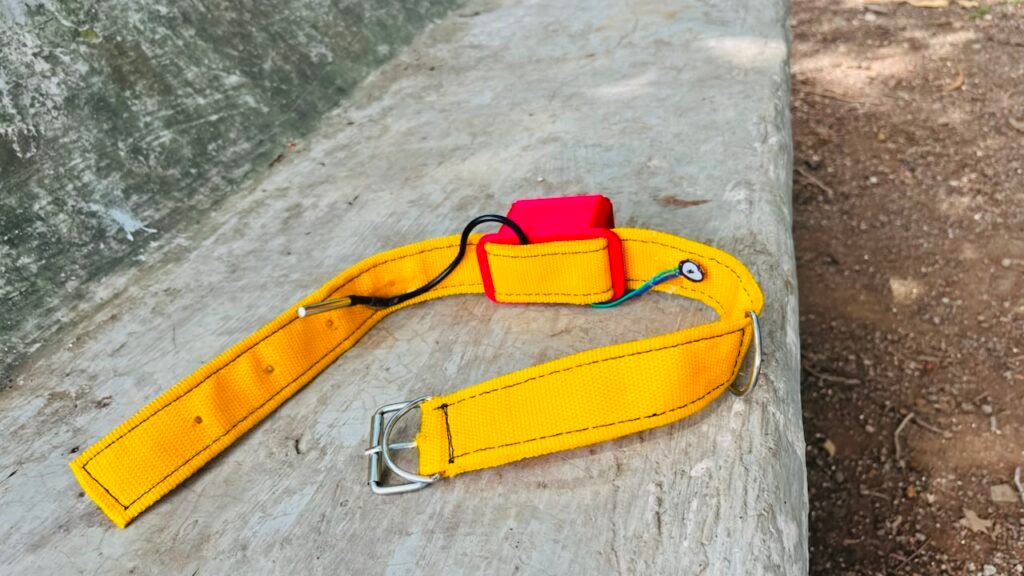
- DS18B20 Temperature Sensor – Measures the cow’s temperature.
- XD-58C Pulse Sensor – Detects the pulse signal and provides BPM readings.
- 0.96-inch OLED Display (I²C) – Displays temperature and pulse rate.
- LED – Indicates that the band is powered ON and working.
- 4.7 kΩ Resistor – Used as a pull-up resistor for the DS18B20 data line.
- Battery / Power Supply – Provides power to the system.
- Connecting Wires – Used to connect the components.
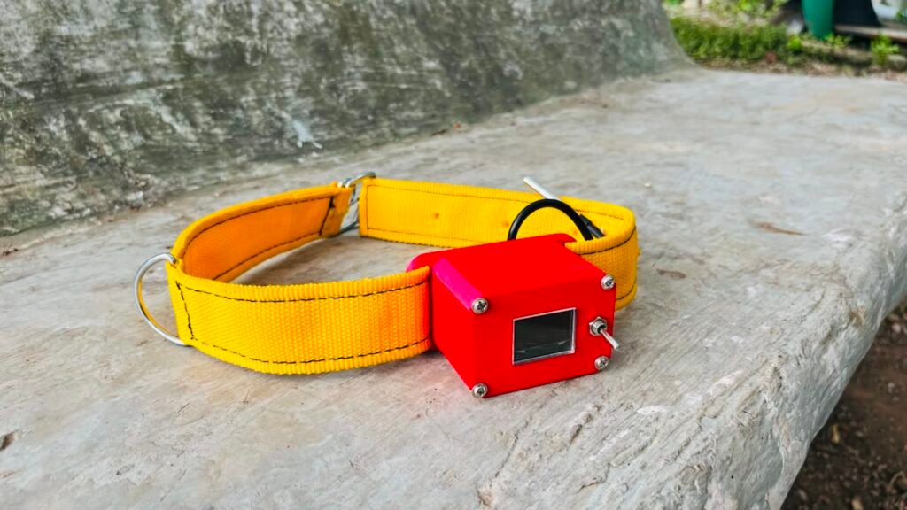
- Cow Neck Band – Holds the electronics and sensors around the cow’s neck.
- Enclosure / 3D-Printed Box – Protects and holds the electronic components.
From Idea to Final Prototype
step 1
reasearch
I started the project by researching different cow health monitoring systems and smart neck bands available online. I looked at existing products and projects to understand their design, sensor placement, size, features, and overall working. This gave me ideas about how I could design my own band and which features would be useful.
Initially, I also planned to add a GPS location system to the band so that the cow’s location could be monitored. I tested the GPS module for about two days, but I was unable to get a reliable GPS signal. Because of this issue, I decided to remove GPS from the final version and focus on the main features that I could make work reliably: temperature and pulse monitoring.
here a example of some cow health monitoring band
https://www.jiogausamriddhi.com
step 2
Ordering Components
After completing the research and deciding the final features, I made a list of the components required for the project. I checked the availability, cost, specifications, and compatibility of the components before ordering them.
I ordered the main components, including the XIAO ESP32-C3, DS18B20 temperature sensor, XD-58C pulse sensor, OLED display, LED, resistor, connecting wires, and other required materials.
After receiving the components, I checked each part for any physical damage and verified that I had received the correct components. I then started testing them individually before combining them into the complete system. This helped avoid problems later during the project development.
| Sr. No. | Component | Quantity | Purpose |
|---|---|---|---|
| 1 | XIAO ESP32-C3 | 1 | Main controller |
| 2 | DS18B20 Temperature Sensor | 1 | Measures temperature |
| 3 | XD-58C Pulse Sensor | 1 | Measures pulse/BPM |
| 4 | 0.96-inch OLED Display | 1 | Displays sensor readings |
| 5 | LED | 1 | Power/working indication |
| 6 | 4.7 kΩ Resistor | 1 | DS18B20 pull-up resistor |
| 7 | Connecting Wires | As required | Circuit connections |
| 8 | Battery / Power Supply | 1 | Powers the system |
| 9 | Cow Neck Band | 1 | Holds the system on the cow |
| 10 | Enclosure / 3D-Printed Box | 1 | Protects the electronics |
| 11 | Breadboard / Prototype Board | 1 | Initial circuit testing |
step 3
testing of components
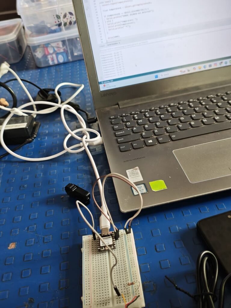
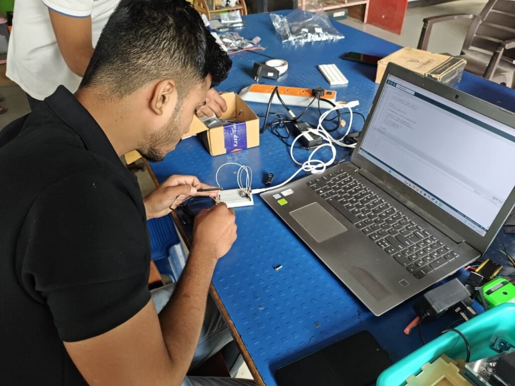
After receiving all the components, I tested them one by one before connecting the complete system. This helped me find problems early and make sure each component was working properly.
First, I tested the XIAO ESP32-C3 by uploading a basic test program. Then I tested the DS18B20 temperature sensor and checked whether it was giving temperature readings correctly. After that, I tested the XD-58C pulse sensor and checked whether it could detect a pulse signal and provide BPM readings.
I also tested the OLED display using I²C communication and confirmed that it was detected at address 0x3C. Finally, I tested the LED and power connections.
Main code
#define BLYNK_TEMPLATE_ID "TMPL3rwQHU3a1"
#define BLYNK_TEMPLATE_NAME "smart cow health band"
#define BLYNK_AUTH_TOKEN "t0vsKdPiBmpQfiFFk-NZ3-ADj9VhSyfI"

#define BLYNK_PRINT Serial

#include <WiFi.h>
#include <BlynkSimpleEsp32.h>

#include <OneWire.h>
#include <DallasTemperature.h>

#include <Wire.h>
#include <Adafruit_GFX.h>
#include <Adafruit_SSD1306.h>

// =====================================================
// WIFI
// =====================================================

char ssid[] = "OnePlus";
char pass[] = "asdfghjkl";

// =====================================================
// PIN CONFIGURATION
// DO NOT CHANGE
// =====================================================

#define TEMP_PIN   D2
#define PULSE_PIN  D0
#define SDA_PIN    D4
#define SCL_PIN    D5
#define LED_PIN    D10

// =====================================================
// OLED
// =====================================================

#define SCREEN_WIDTH 128
#define SCREEN_HEIGHT 64
#define OLED_RESET -1

Adafruit_SSD1306 display(
  SCREEN_WIDTH,
  SCREEN_HEIGHT,
  &Wire,
  OLED_RESET
);

// =====================================================
// DS18B20
// =====================================================

OneWire oneWire(TEMP_PIN);
DallasTemperature sensors(&oneWire);

float temperature = -127.0;

// =====================================================
// PULSE SENSOR
// =====================================================

int rawPulse = 0;
int smoothPulse = 0;

int signalMin = 4095;
int signalMax = 0;

int dynamicThreshold = 0;

bool pulseState = false;

unsigned long lastBeatTime = 0;
unsigned long signalStartTime = 0;
unsigned long lastPulseRead = 0;

// =====================================================
// BPM AVERAGING
// =====================================================

#define BPM_SAMPLES 5

int bpmValues[BPM_SAMPLES];
int bpmIndex = 0;
int bpmCount = 0;

int averageBPM = 0;

// =====================================================
// TIMERS
// =====================================================

unsigned long lastTemperatureRead = 0;
unsigned long lastDisplay = 0;
unsigned long lastSerial = 0;
unsigned long lastBlynkSend = 0;

// =====================================================
// ADD BPM
// =====================================================

void addBPM(int bpm)
{
  bpmValues[bpmIndex] = bpm;

  bpmIndex++;

  if (bpmIndex >= BPM_SAMPLES)
  {
    bpmIndex = 0;
  }

  if (bpmCount < BPM_SAMPLES)
  {
    bpmCount++;
  }

  long total = 0;

  for (int i = 0; i < bpmCount; i++)
  {
    total += bpmValues[i];
  }

  averageBPM = total / bpmCount;
}

// =====================================================
// SETUP
// =====================================================

void setup()
{
  Serial.begin(115200);

  delay(1000);

  Serial.println();
  Serial.println("==============================");
  Serial.println(" COW MONITORING BAND");
  Serial.println("==============================");

  // ---------------------------------------------------
  // LED
  // ---------------------------------------------------

  pinMode(LED_PIN, OUTPUT);
  digitalWrite(LED_PIN, LOW);

  // ---------------------------------------------------
  // PULSE SENSOR
  // ---------------------------------------------------

  pinMode(PULSE_PIN, INPUT);

  // ---------------------------------------------------
  // I2C OLED
  // ---------------------------------------------------

  Wire.begin(SDA_PIN, SCL_PIN);

  if (!display.begin(SSD1306_SWITCHCAPVCC, 0x3C))
  {
    Serial.println("OLED NOT FOUND!");
  }
  else
  {
    Serial.println("OLED FOUND!");

    display.clearDisplay();

    display.setTextColor(SSD1306_WHITE);

    display.setTextSize(1);
    display.setCursor(20, 20);
    display.println("COW MONITORING");

    display.setCursor(25, 35);
    display.println("Starting...");

    display.display();

    delay(1500);
  }

  // ---------------------------------------------------
  // DS18B20
  // ---------------------------------------------------

  sensors.begin();

  Serial.println("DS18B20 started");

  // ---------------------------------------------------
  // INITIAL PULSE VALUES
  // ---------------------------------------------------

  smoothPulse = analogRead(PULSE_PIN);

  signalMin = smoothPulse - 300;
  signalMax = smoothPulse + 300;

  if (signalMin < 0)
  {
    signalMin = 0;
  }

  if (signalMax > 4095)
  {
    signalMax = 4095;
  }

  signalStartTime = millis();

  // ---------------------------------------------------
  // WIFI
  // ---------------------------------------------------

  Serial.println("Connecting to WiFi...");

  WiFi.begin(ssid, pass);

  unsigned long wifiStart = millis();

  while (WiFi.status() != WL_CONNECTED &&
         millis() - wifiStart < 15000)
  {
    delay(500);

    Serial.print(".");
  }

  Serial.println();

  if (WiFi.status() == WL_CONNECTED)
  {
    Serial.println("WiFi connected!");

    Serial.print("IP Address: ");
    Serial.println(WiFi.localIP());

    // -------------------------------------------------
    // BLYNK
    // -------------------------------------------------

    Blynk.config(BLYNK_AUTH_TOKEN);

    Blynk.connect(5000);

    if (Blynk.connected())
    {
      Serial.println("Blynk connected!");
    }
    else
    {
      Serial.println("Blynk not connected.");
    }
  }
  else
  {
    Serial.println("WiFi connection failed.");
    Serial.println("Sensor system will continue.");
  }
}

// =====================================================
// LOOP
// =====================================================

void loop()
{
  // ===================================================
  // BLYNK
  // ===================================================

  if (WiFi.status() == WL_CONNECTED)
  {
    Blynk.run();
  }

  // ===================================================
  // TEMPERATURE
  // READ EVERY 1 SECOND
  // ===================================================

  if (millis() - lastTemperatureRead >= 1000)
  {
    lastTemperatureRead = millis();

    sensors.requestTemperatures();

    float temp = sensors.getTempCByIndex(0);

    if (temp != DEVICE_DISCONNECTED_C &&
        temp > -55 &&
        temp < 100)
    {
      temperature = temp;
    }
    else
    {
      temperature = -127;
    }
  }

  // ===================================================
  // PULSE SENSOR
  // READ EVERY 20 ms
  // ===================================================

  if (millis() - lastPulseRead >= 20)
  {
    lastPulseRead = millis();

    rawPulse = analogRead(PULSE_PIN);

    // -------------------------------------------------
    // SMOOTH PULSE SIGNAL
    // -------------------------------------------------

    smoothPulse =
      (smoothPulse * 3 + rawPulse) / 4;

    // -------------------------------------------------
    // LEARN MINIMUM
    // -------------------------------------------------

    if (smoothPulse < signalMin)
    {
      signalMin = smoothPulse;
    }

    // -------------------------------------------------
    // LEARN MAXIMUM
    // -------------------------------------------------

    if (smoothPulse > signalMax)
    {
      signalMax = smoothPulse;
    }

    // -------------------------------------------------
    // ADAPTIVE THRESHOLD
    // -------------------------------------------------

    dynamicThreshold =
      signalMin +
      ((signalMax - signalMin) * 60 / 100);

    // -------------------------------------------------
    // HEARTBEAT DETECTION
    // -------------------------------------------------

    unsigned long now = millis();

    if (smoothPulse > dynamicThreshold &&
        !pulseState)
    {
      pulseState = true;

      // Prevent beats too close together
      if (lastBeatTime == 0 ||
          now - lastBeatTime > 400)
      {
        if (lastBeatTime != 0)
        {
          unsigned long interval =
            now - lastBeatTime;

          // Approximately 35–180 BPM
          if (interval >= 333 &&
              interval <= 1714)
          {
            int currentBPM =
              60000 / interval;

            if (currentBPM >= 35 &&
                currentBPM <= 180)
            {
              addBPM(currentBPM);

              Serial.print("BEAT = ");
              Serial.print(currentBPM);

              Serial.print(" BPM | AVERAGE = ");
              Serial.println(averageBPM);
            }
          }
        }

        lastBeatTime = now;

        digitalWrite(LED_PIN, HIGH);
      }
    }

    // -------------------------------------------------
    // SIGNAL GOES DOWN
    // -------------------------------------------------

    if (smoothPulse < dynamicThreshold - 100)
    {
      pulseState = false;

      digitalWrite(LED_PIN, LOW);
    }

    // -------------------------------------------------
    // RESET SIGNAL RANGE EVERY 5 SECONDS
    // -------------------------------------------------

    if (millis() - signalStartTime >= 5000)
    {
      signalStartTime = millis();

      int current = smoothPulse;

      signalMin = current - 300;
      signalMax = current + 300;

      if (signalMin < 0)
      {
        signalMin = 0;
      }

      if (signalMax > 4095)
      {
        signalMax = 4095;
      }
    }
  }

  // ===================================================
  // SERIAL OUTPUT EVERY 500 ms
  // ===================================================

  if (millis() - lastSerial >= 500)
  {
    lastSerial = millis();

    Serial.print("Pulse: ");
    Serial.print(rawPulse);

    Serial.print(" | Smooth: ");
    Serial.print(smoothPulse);

    Serial.print(" | Threshold: ");
    Serial.print(dynamicThreshold);

    Serial.print(" | BPM: ");

    if (averageBPM > 0)
    {
      Serial.println(averageBPM);
    }
    else
    {
      Serial.println("Waiting...");
    }
  }

  // ===================================================
  // OLED
  // ===================================================

  if (millis() - lastDisplay >= 500)
  {
    lastDisplay = millis();

    display.clearDisplay();

    display.setTextColor(SSD1306_WHITE);

    // -------------------------------------------------
    // TITLE
    // -------------------------------------------------

    display.setTextSize(1);

    display.setCursor(0, 0);
    display.println("COW MONITORING");

    display.drawLine(
      0,
      11,
      128,
      11,
      SSD1306_WHITE
    );

    // -------------------------------------------------
    // TEMPERATURE
    // -------------------------------------------------

    display.setCursor(0, 18);

    display.print("Temp: ");

    if (temperature == -127)
    {
      display.println("FAILED");
    }
    else
    {
      display.print(temperature, 1);
      display.println(" C");
    }

    // -------------------------------------------------
    // BPM
    // -------------------------------------------------

    display.setCursor(0, 34);

    display.print("Heart: ");

    if (averageBPM > 0)
    {
      display.print(averageBPM);
      display.println(" BPM");
    }
    else
    {
      display.println("Waiting...");
    }

    // -------------------------------------------------
    // PULSE
    // -------------------------------------------------

    display.setCursor(0, 50);

    display.print("Pulse: ");
    display.println(rawPulse);

    display.display();
  }

  // ===================================================
  // BLYNK DATA
  // SEND EVERY 1 SECOND
  // ===================================================

  if (millis() - lastBlynkSend >= 1000)
  {
    lastBlynkSend = millis();

    if (Blynk.connected())
    {
      // -----------------------------------------------
      // V0 = TEMPERATURE
      // -----------------------------------------------

      if (temperature != -127)
      {
        Blynk.virtualWrite(V0, temperature);
      }

      // -----------------------------------------------
      // V1 = BPM
      // -----------------------------------------------

      Blynk.virtualWrite(V1, averageBPM);

      // -----------------------------------------------
      // V2 = RAW PULSE
      // -----------------------------------------------

      Blynk.virtualWrite(V2, rawPulse);

      // -----------------------------------------------
      // V3 = BAND STATUS
      // 1 = ONLINE
      // -----------------------------------------------

      Blynk.virtualWrite(V3, 1);

      // -----------------------------------------------
      // V4 = TEMPERATURE STATUS
      // -----------------------------------------------

      if (temperature == -127)
      {
        Blynk.virtualWrite(
          V4,
          "TEMP SENSOR ERROR"
        );
      }
      else
      {
        Blynk.virtualWrite(
          V4,
          "TEMPERATURE OK"
        );
      }

      // -----------------------------------------------
      // V5 = HEART STATUS
      // -----------------------------------------------

      if (averageBPM > 0)
      {
        Blynk.virtualWrite(
          V5,
          "HEART RATE DETECTED"
        );
      }
      else
      {
        Blynk.virtualWrite(
          V5,
          "WAITING FOR PULSE"
        );
      }
    }
  }
}
step 4
Creating the Blynk App
After testing the hardware components, I created a Blynk IoT dashboard to monitor the data from the Smart Cow Health Band. The purpose was to make the sensor readings available on a mobile phone instead of displaying them only on the OLED.
First, I created a Blynk template for the project and connected the XIAO ESP32-C3 to Blynk through Wi-Fi. I then created virtual data channels for the temperature and pulse rate (BPM).
After setting up the dashboard widgets, I programmed the XIAO ESP32-C3 to send the sensor readings to Blynk. I tested the connection and checked whether the temperature and BPM values were being updated correctly in the app.
This step added remote monitoring to the project and made it easier to view the cow’s readings.
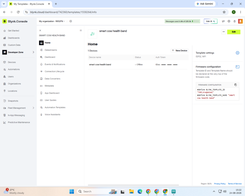
creating a template
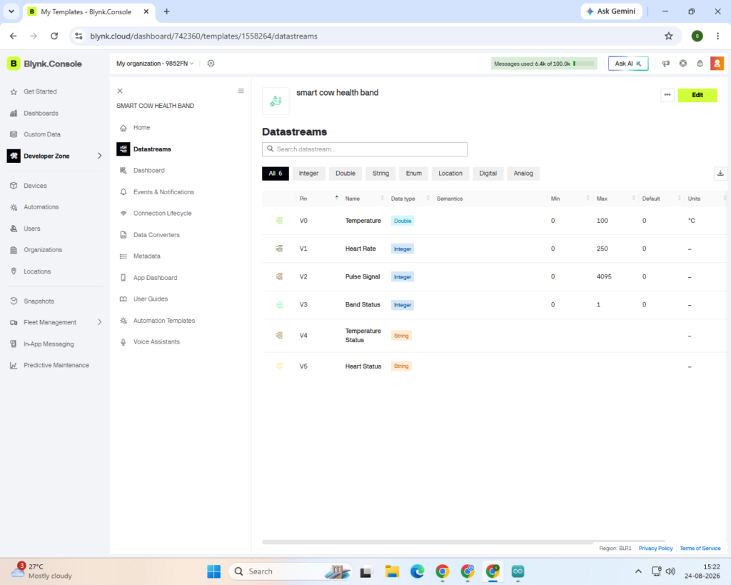
creating datastreams
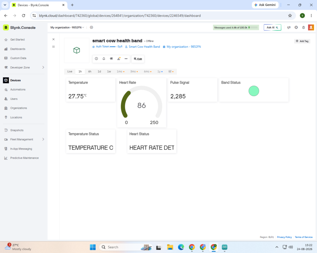
Step 5
Testing the Blynk App
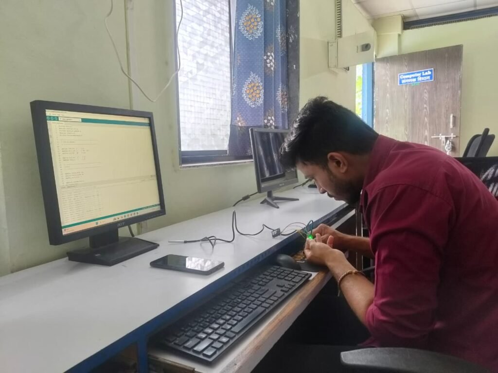
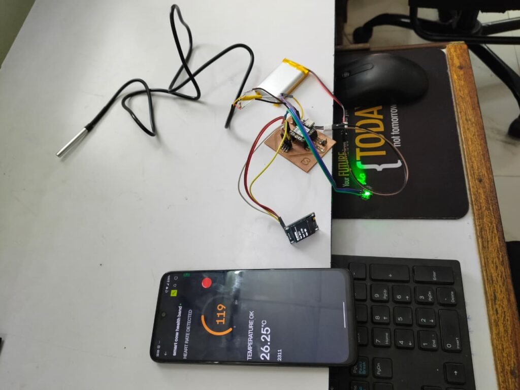
After creating the Blynk dashboard, I tested the app with the complete hardware setup. I connected the XIAO ESP32-C3 to Wi-Fi and checked whether it could successfully send the sensor data to Blynk.
I tested the temperature and BPM readings and compared the values shown on the Blynk app with the readings displayed on the OLED. I also checked whether the values were updating properly without major delays.
After testing, the Blynk app was working properly and could be used to monitor the cow’s temperature and pulse rate remotely.
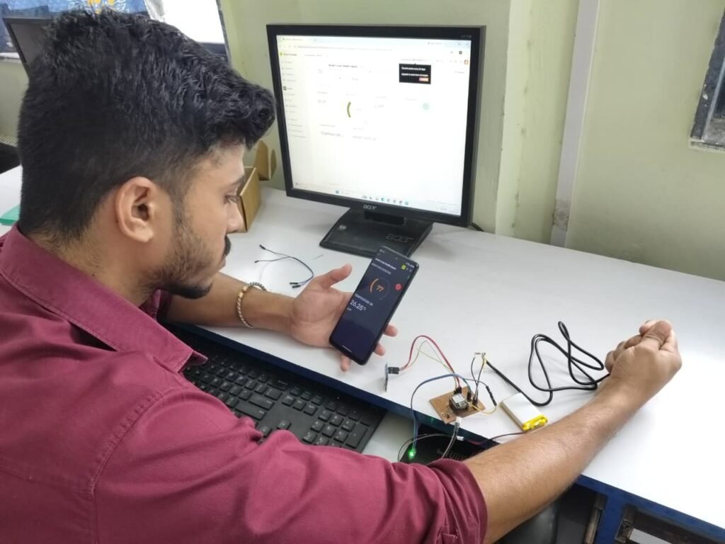
testing
Step 6
PCB Design
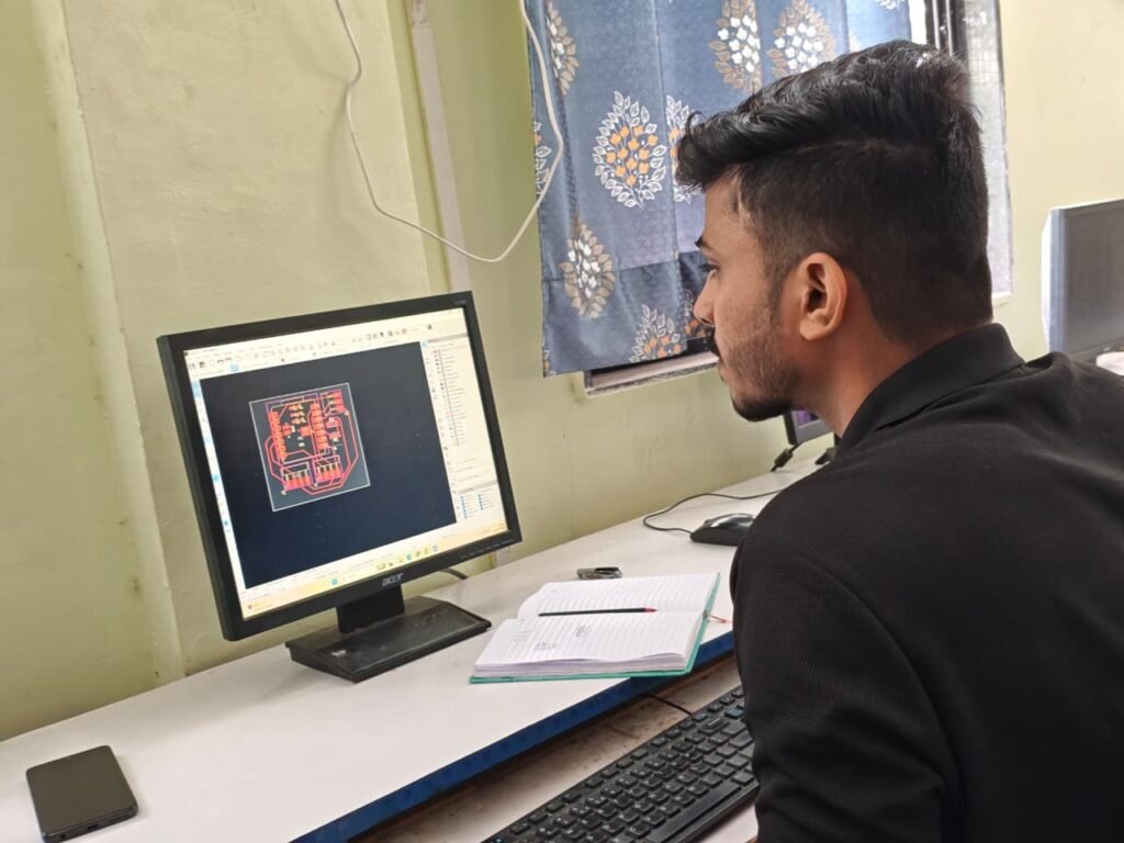
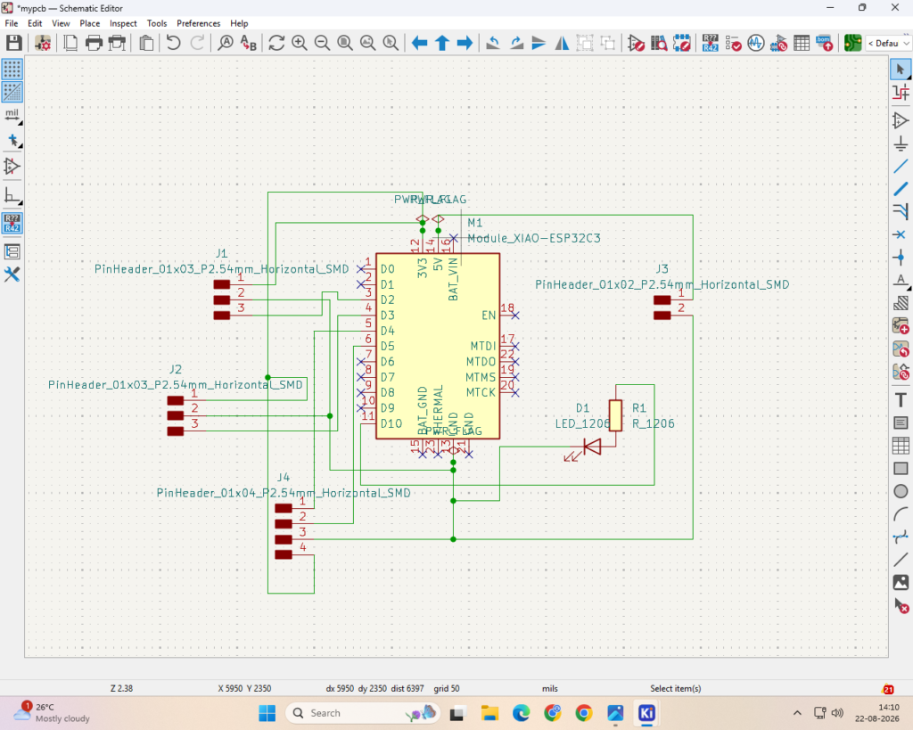
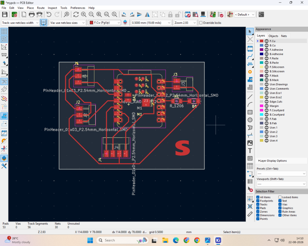
After testing the complete circuit on a breadboard, I started designing the PCB to make the project more compact, neat, and reliable. I created the circuit layout based on the final pin connections of the XIAO ESP32-C3, DS18B20, XD-58C pulse sensor, OLED, and LED.
I arranged the components and connections carefully to reduce loose wires and make the final circuit easier to install inside the cow health band. Before finalizing the PCB design, I checked the connections, pin numbers, power lines, and component placement to avoid errors.
The PCB design was then prepared for fabrication and integration into the final project enclosure.
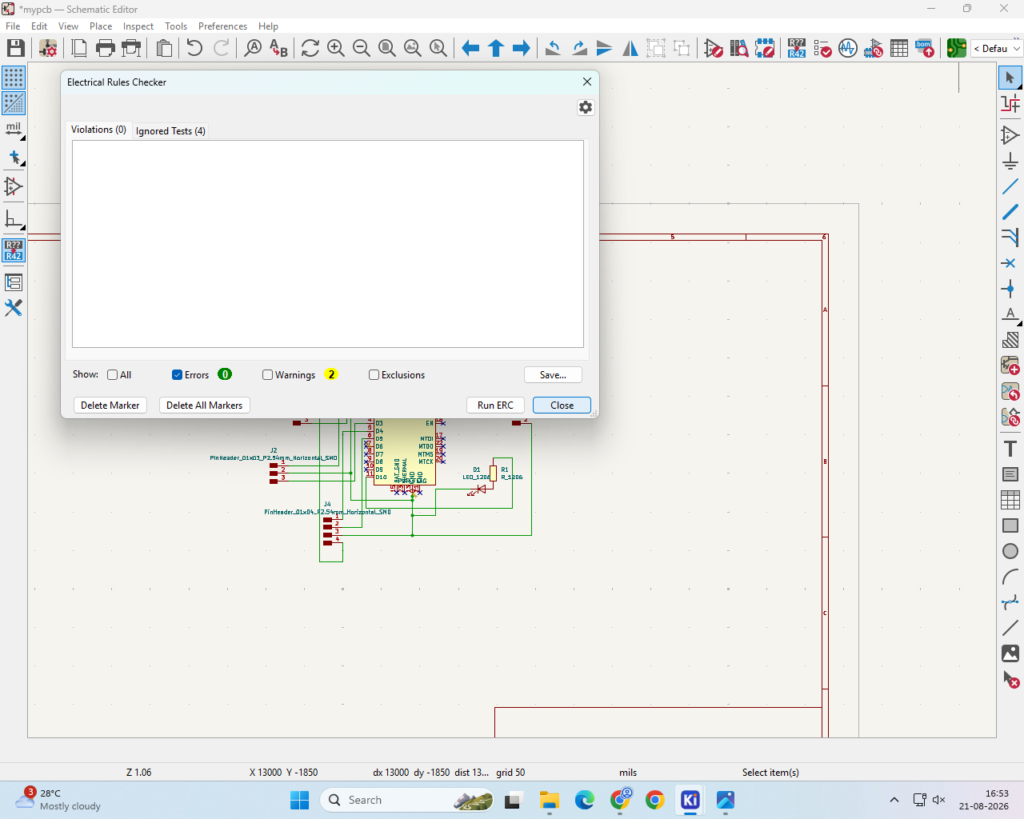
electric rule check
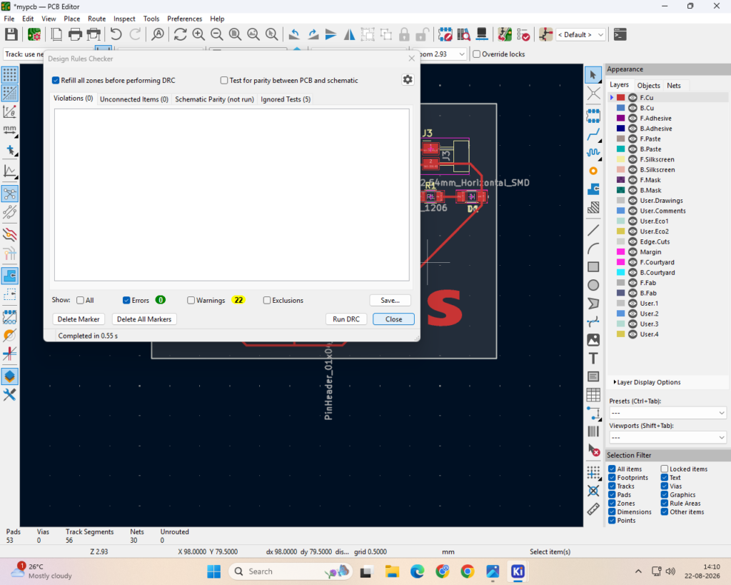
design rule check
step 7
pcb milling
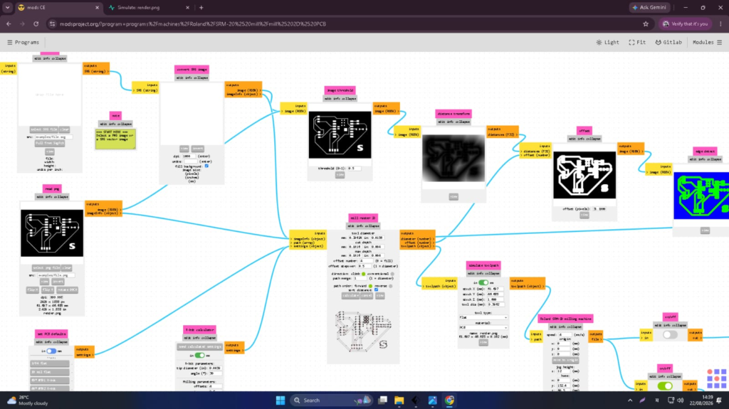
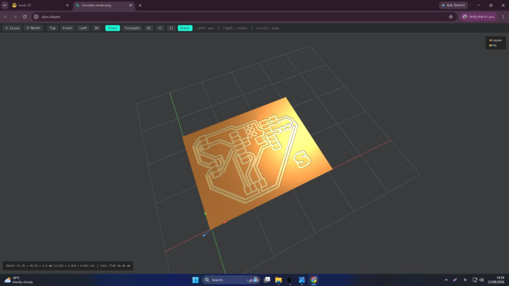
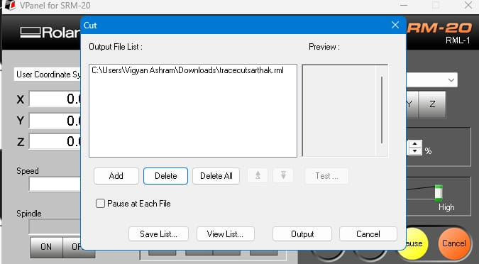
After completing the PCB design, I prepared the design for PCB milling. The PCB milling machine was used to remove the unwanted copper and create the required tracks according to the circuit layout.
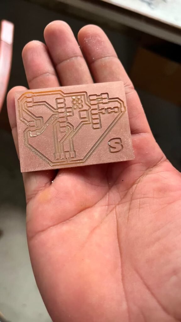
First, I fixed the copper-clad board properly on the milling machine. Then I loaded the PCB design and started the milling process. After milling, I cleaned the board and checked the tracks for any broken connections or unwanted shorts.
Once the PCB was ready, I checked the important connections using a multimeter before moving on to component soldering.
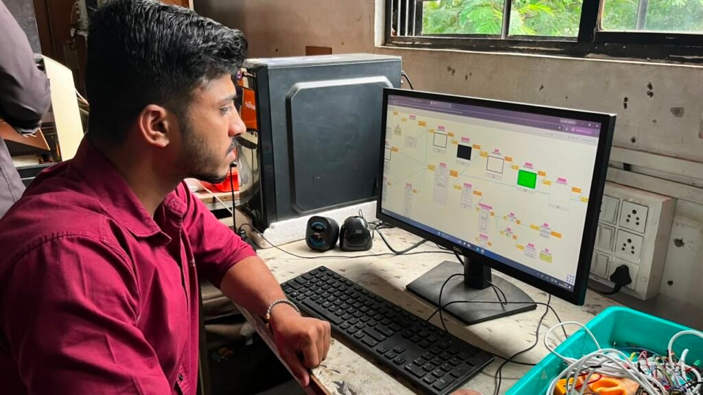
png to RML
final pcb
Step 8 –
soldering
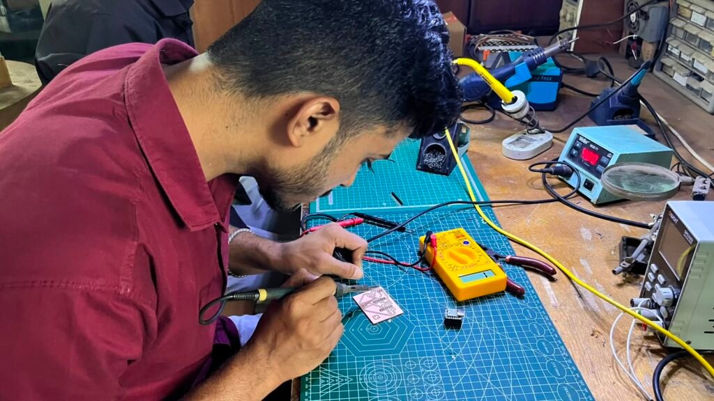
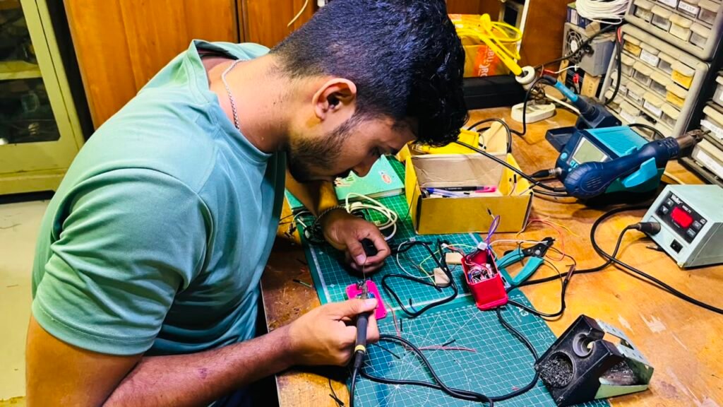
After milling the PCB, I started soldering the male connectors onto the board. I first checked the component placement and then soldered the required connections carefully.
The XIAO ESP32-C3, LED, resistor, and connector points for the DS18B20, XD-58C pulse sensor, and OLED were connected according to the final circuit design. After soldering, I checked the joints and tested the PCB with a multimeter to make sure there were no loose connections or short circuits.
Finally, I connected the sensors and OLED to the PCB and tested the complete hardware setup before moving to the final assembly
Step 9
Pcb testing
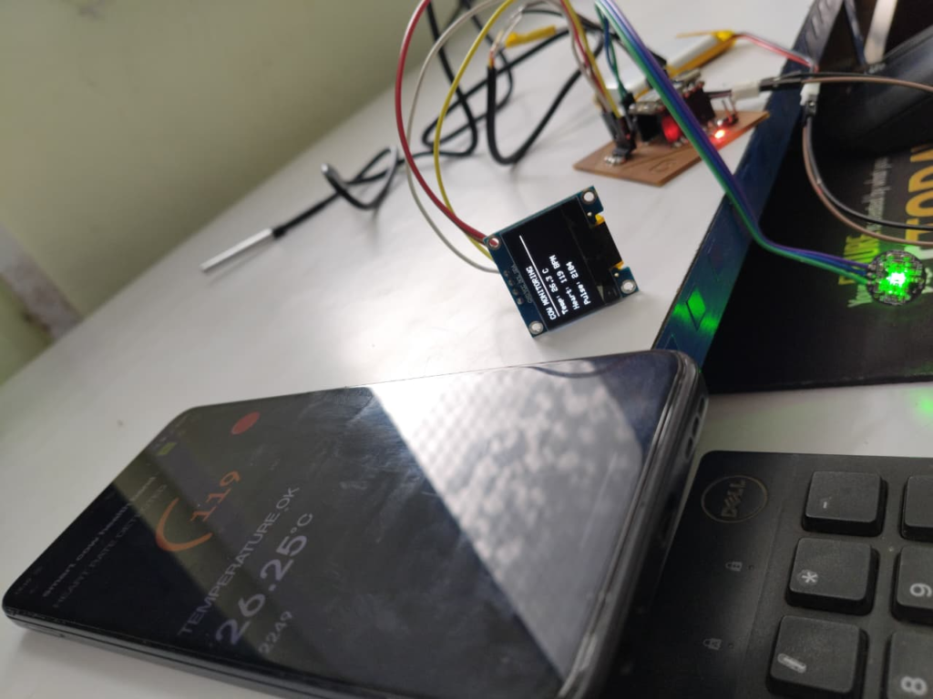
After soldering all the components, I tested the PCB to make sure everything was connected and working properly. First, I checked the PCB tracks and solder joints for any loose connections or short circuits using a multimeter.
Then I powered the board and tested the XIAO ESP32-C3, DS18B20 temperature sensor, XD-58C pulse sensor, OLED display, and LED. I checked whether the temperature and BPM readings were being received correctly and displayed on the OLED.
After confirming that all the main functions were working, I tested the PCB together with the Blynk app. This confirmed that the final PCB was ready to be installed into the cow health band.
Step 10 –
3D Design and Case Design
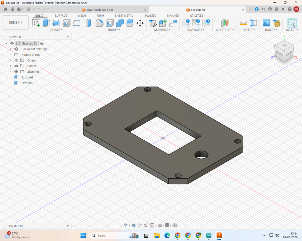
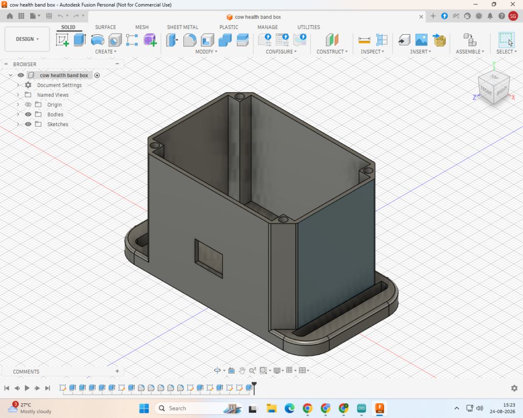
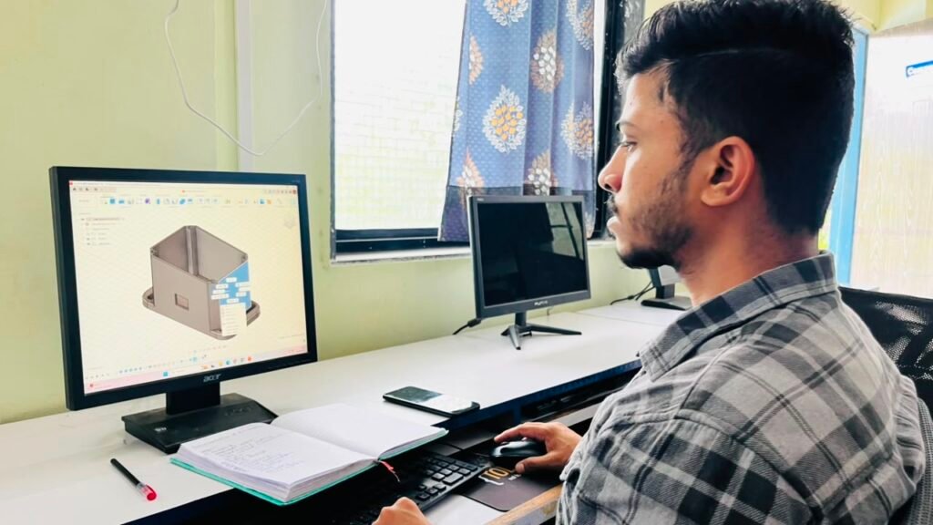
After completing and testing the PCB, I designed a protective case for the electronics using Autodesk Fusion 360. I first measured the PCB and the required components so that the case would fit them properly.
I designed the case with suitable spaces for the PCB, OLED display, sensor wires, power connection, and other components. I also considered the size and shape of the case so that it could be attached comfortably to the cow’s neck band.
After completing the 3D model, I checked the design and prepared it for 3D printing. The final case helps protect the electronics from physical damage and keeps the project compact and organized.
Step 11 – 3D Printing
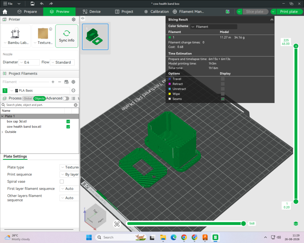
After completing the case design in Fusion 360, I prepared the 3D model for printing. I used a Bambu Lab A1 3D printer to manufacture the case.
I first checked the dimensions and orientation of the model and then prepared the file for printing. After printing, I removed the support material and checked the case to make sure the PCB and other components fit properly.
The 3D-printed case gave the project a clean and compact finish and provided protection for the electronic components.
Step 12
Assembly
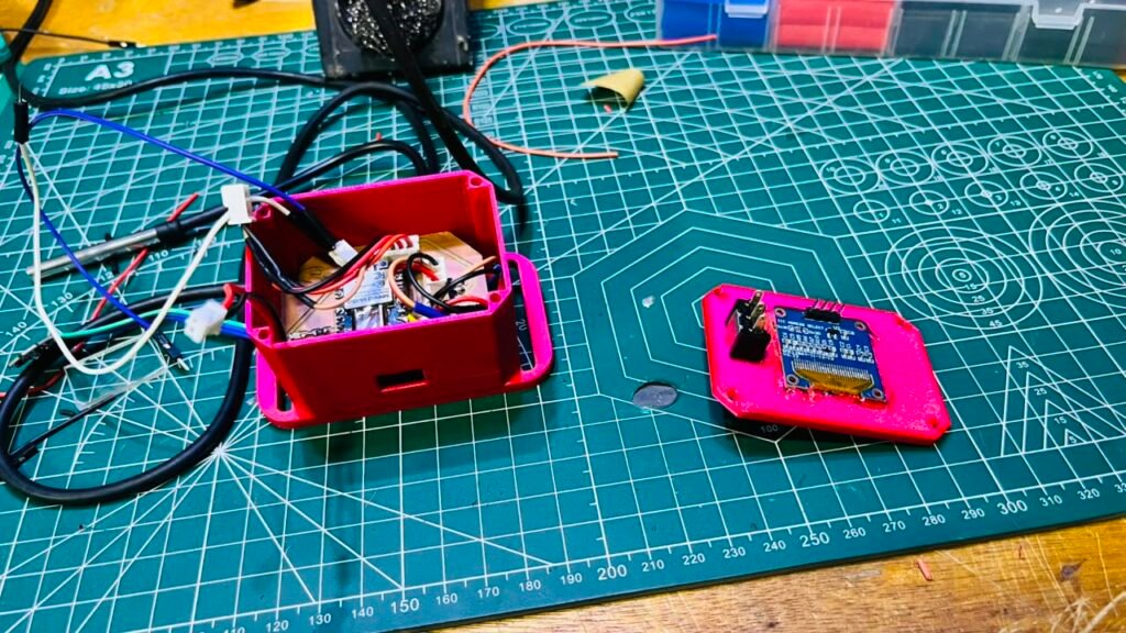
After completing the PCB and 3D-printed case, I started the final assembly of the Smart Cow Health Band. I first placed the PCB inside the 3D-printed case and connected the DS18B20 temperature sensor, XD-58C pulse sensor, OLED display, LED, and power supply.
I then fixed the case securely to the cow’s neck band and positioned the sensors properly for testing. After assembling everything, I powered on the system and checked the OLED display, temperature, pulse rate, LED indication, and Blynk app.
Finally, I tested the complete band to make sure all the parts were working together properly before the final demonstration.
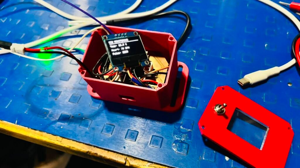
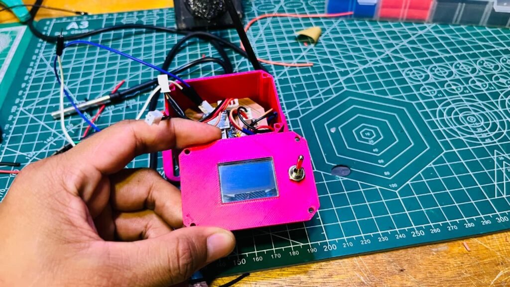
soldering and assembly
Step 13
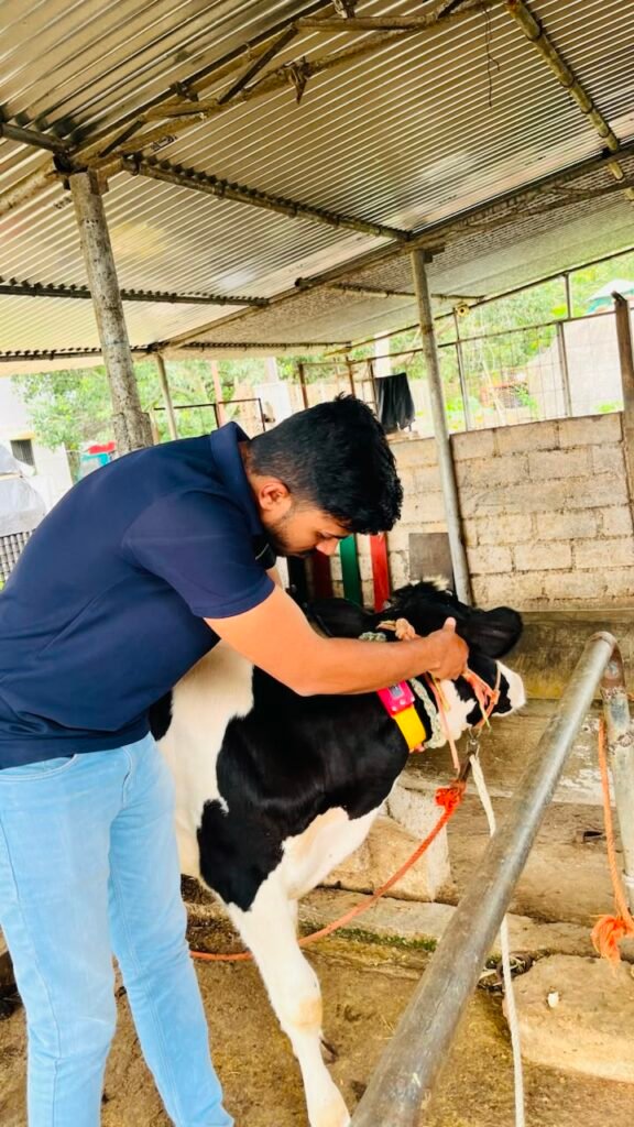
Testing on Cow and Sensor Position
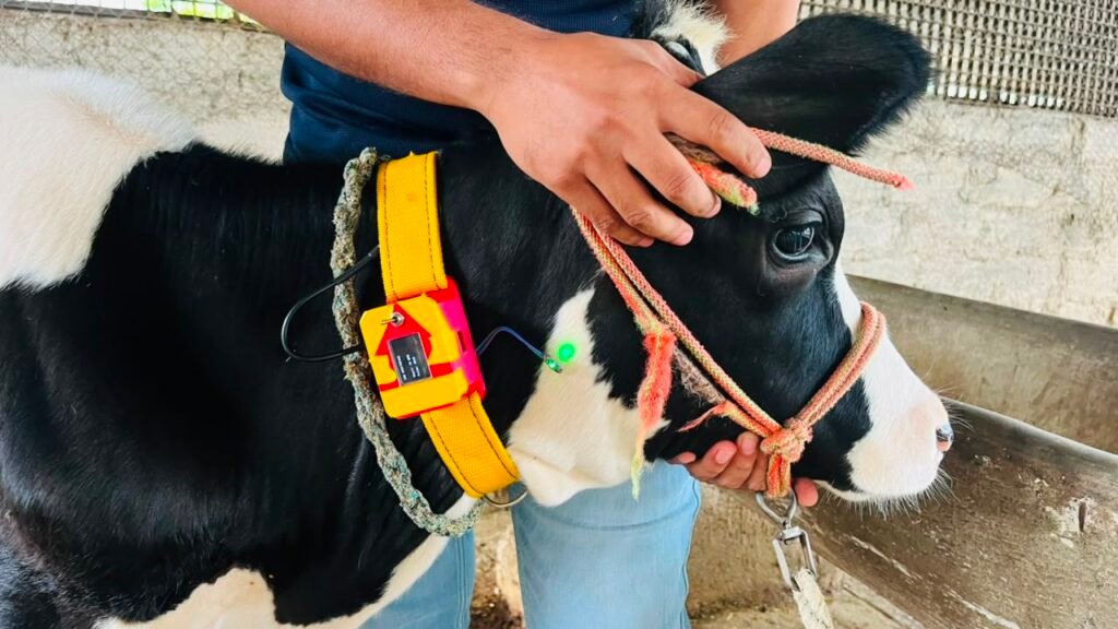
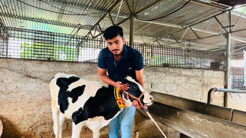
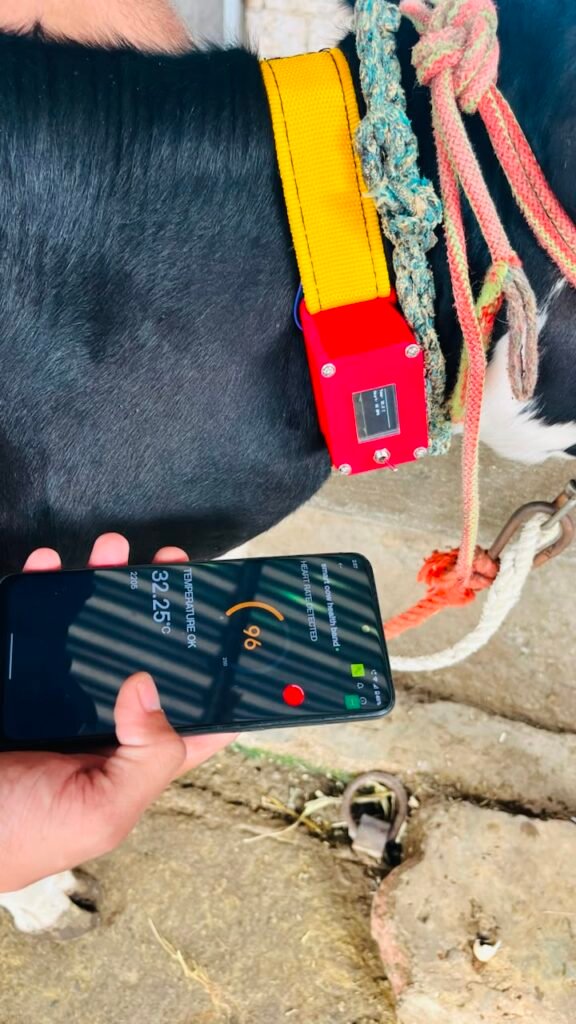
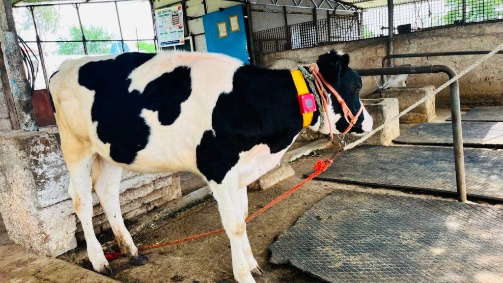
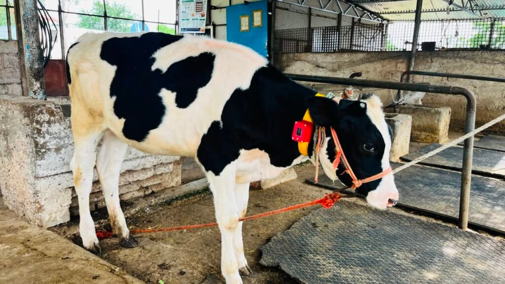
After completing the final assembly, I tested the Smart Cow Health Band on a cow. The main purpose of this step was to find and confirm the proper position of the sensors on the cow’s neck.
I tried different positions for the DS18B20 temperature sensor and XD-58C pulse sensor and checked the sensor readings at each position. Based on the readings and sensor contact, I selected the position where the sensors gave the most stable and usable results.
This step was important because proper sensor placement directly affects the quality of the readings. After confirming the positions, I marked them for the final setup of the band.
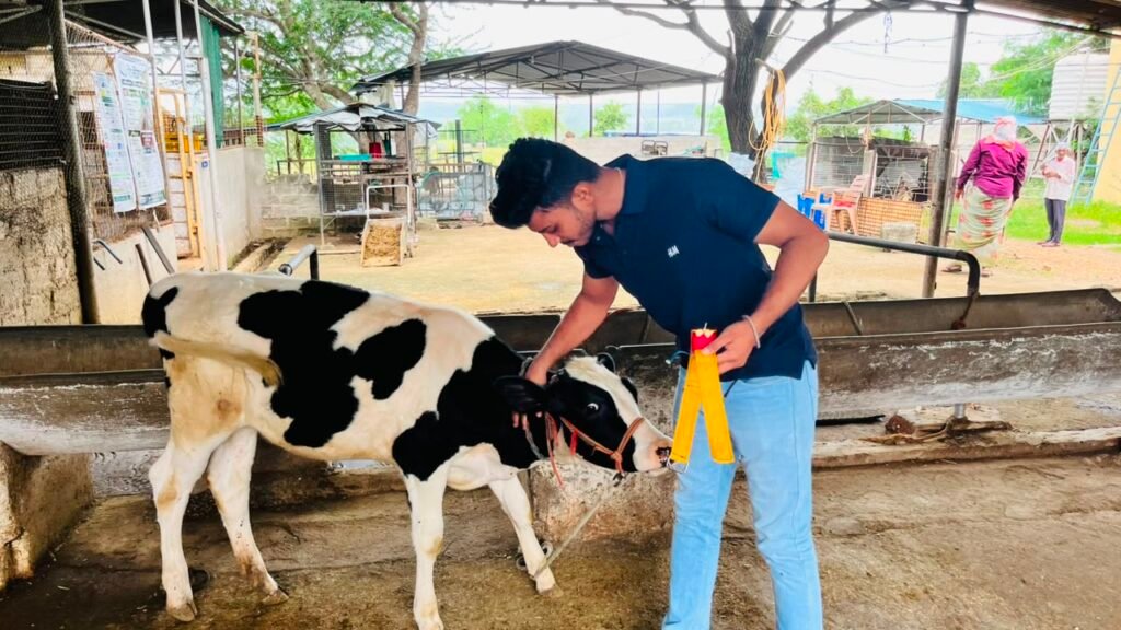
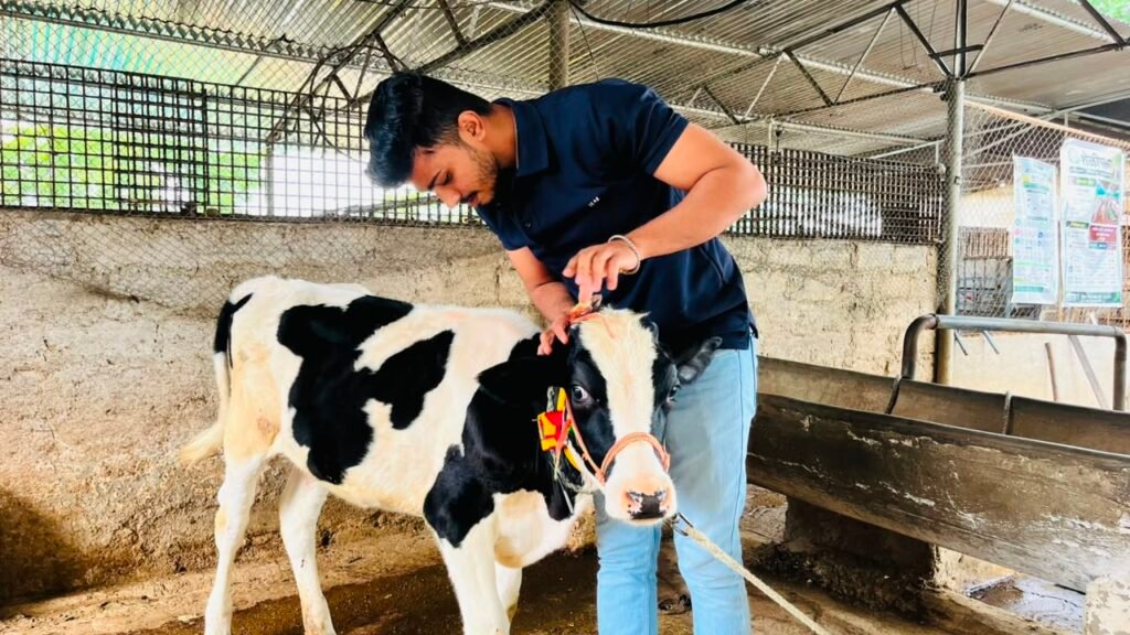
Step 14
Final Testing
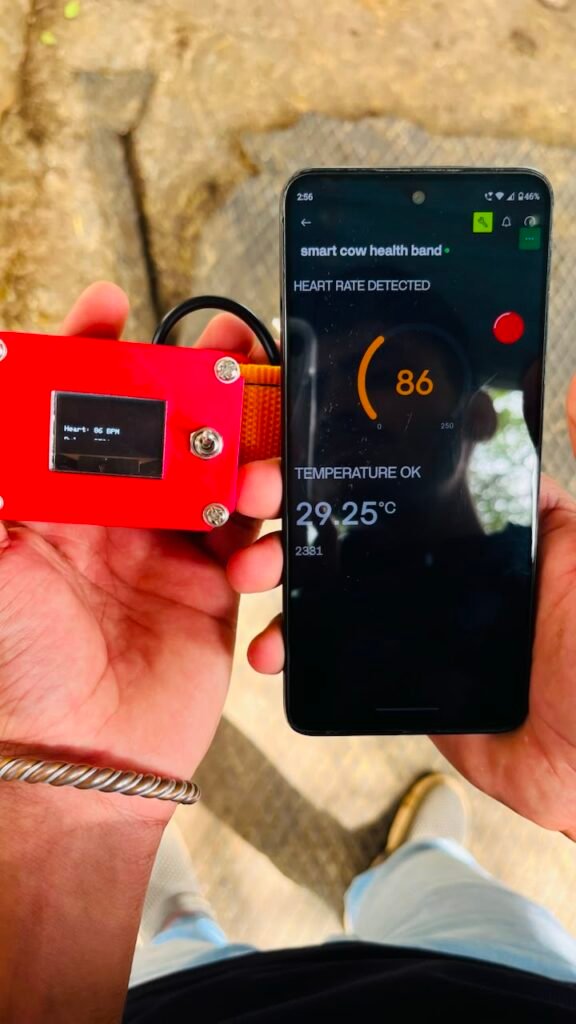
After completing the assembly and confirming the sensor positions, I performed the final testing of the complete Smart Cow Health Band. I checked all the main functions of the system, including the DS18B20 temperature sensor, XD-58C pulse sensor, OLED display, LED, XIAO ESP32-C3, and Blynk app.
I tested the band on the cow and checked whether the sensors were giving usable readings in the selected positions. I also checked the connections, power supply, OLED display, and Blynk data to make sure everything was working together properly.
After completing the final testing, the Smart Cow Health Band was ready for the final demonstration and documentation.
Final Testing Result
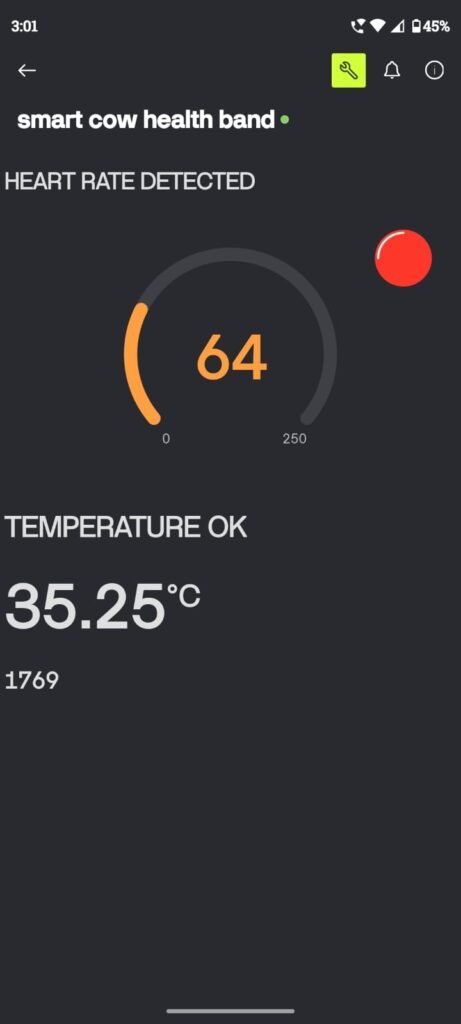
During the final testing on the cow, the XD-58C pulse sensor measured approximately 64 BPM, while the DS18B20 temperature sensor showed a temperature of around 36°C.
These readings confirmed that the sensors were able to collect and display data when the band was fitted on the cow. The readings may vary depending on the cow’s activity, sensor position, contact, and environmental conditions.
Bill of Materials & Project Cost
| Sr. No. | Component / Material | Qty. | Unit Cost | Total Cost |
|---|---|---|---|---|
| 1 | XIAO ESP32-C3 | 1 | ₹779.00 | ₹779.00 |
| 2 | 0.96″ OLED Display | 1 | ₹229.00 | ₹229.00 |
| 3 | DS18B20 temperature sensor | 1 | ₹49.00 | ₹49.00 |
| 4 | XD-58C pulse sensor | 1 | ₹149.00 | ₹149.00 |
| 5 | belt | 1 | ₹100.00 | ₹100.00 |
| 6 | switch | 1 | ₹63.00 | ₹63.00 |
| 7 | PLA+ Filament | 35 g | ₹0.78/g | ₹27.00 |
| 8 | battery | 1 | ₹329.00 | ₹329.00 |
| Total | ₹1725.00 |
Note: PCB fabrication, wires, resistors and other miscellaneous materials are not included in this calculation and can be added separately if required.
Challenges Faced
During the development of the Smart Cow Health Band, I faced several practical challenges:
- GPS problem: Initially, I planned to add GPS for location tracking, but I could not get a reliable GPS signal even after testing it for two days. Because of this, I removed GPS from the final project.
- Temperature sensor issue: The DS18B20 worked with Arduino Uno but initially had problems working with the XIAO ESP32-C3. I had to check the wiring, power supply, pull-up resistor, and code.
- Pulse sensor: Getting stable BPM readings from the XD-58C was difficult because the reading changes with sensor position, movement, and contact with the cow.
- OLED communication: I faced problems while connecting the OLED, but later confirmed its I²C address as 0x3C.
- Blynk connection: Setting up Wi-Fi, the Blynk template, and displaying the sensor data correctly required several tests.
- PCB: Designing and milling the PCB required careful checking of the pin connections and tracks to avoid mistakes.
- Sensor placement: Finding a suitable position for the temperature and pulse sensors on the cow was challenging because the cow moves and the sensor needs proper contact.
- Final assembly: Making the electronics compact enough to fit inside the 3D-printed case and attach comfortably to the neck band required several adjustments.
These challenges helped me understand that building a working prototype involves testing, troubleshooting, redesigning, and improving the system step by step.
Future Scope
The current Smart Cow Health Band is a working prototype, but it can be improved further to make it more useful for real farm applications.
- GPS tracking can be added to monitor the cow’s location. I initially tried GPS but removed it because I could not get a reliable signal during testing.
- Better animal pulse sensing can be used to improve BPM accuracy and reliability.
- More accurate temperature measurement can be added using a sensor and placement specifically designed for cattle.
- Mobile alerts can be added so the farmer receives a notification when readings go outside a selected range.
- Cloud data storage can be used to save the cow’s health readings and view them over time.
- Activity monitoring can be added using an accelerometer to detect movement, rest, or unusual activity.
- Longer battery life can be achieved through better power management.
- The enclosure can be made more waterproof, durable, and comfortable for long-term use.
- The system can be expanded to monitor multiple cows from one dashboard.
- With enough reliable data, future versions could use data analysis or AI to identify unusual patterns and provide early warnings.
Overall Experience
Working on the Smart Cow Health Band was a very good learning experience for me. I learned how to take an idea from the research stage and turn it into a working prototype. During the project, I worked with sensors, the XIAO ESP32-C3, PCB design, PCB milling, soldering, Blynk, Fusion 360, and 3D printing.
I also faced many problems during development, such as the GPS not getting a signal, sensor readings not being stable, connection issues, and finding the correct sensor positions on the cow. Solving these problems taught me the importance of testing, troubleshooting, and making improvements step by step.
The most valuable part of the project was testing the final band on a real cow and seeing the sensors produce actual readings. Overall, this project improved my technical skills, problem-solving ability, and confidence in building real-world projects.
Vigyan Ashram Blog Site Link
https://vadic.vigyanashram.blog/author/sarthakgosavi7
END OF PROJECT REPORT