Project Title- Smart Cutoff Plug
Student Name: Shivam Anand Gosavi
Project Introduction
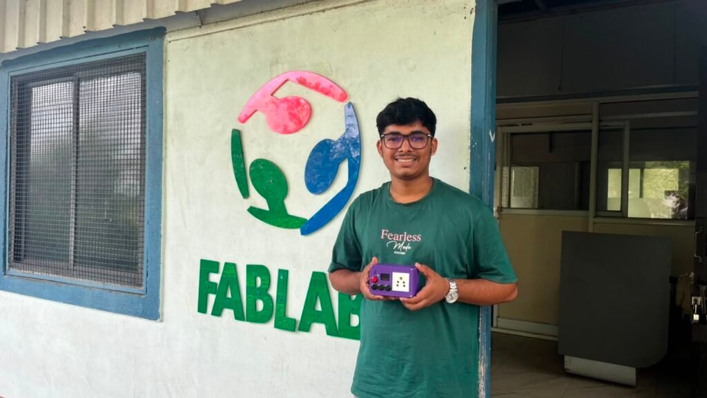
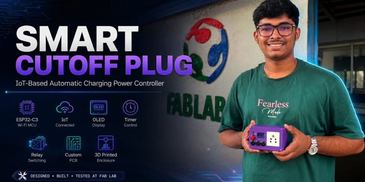
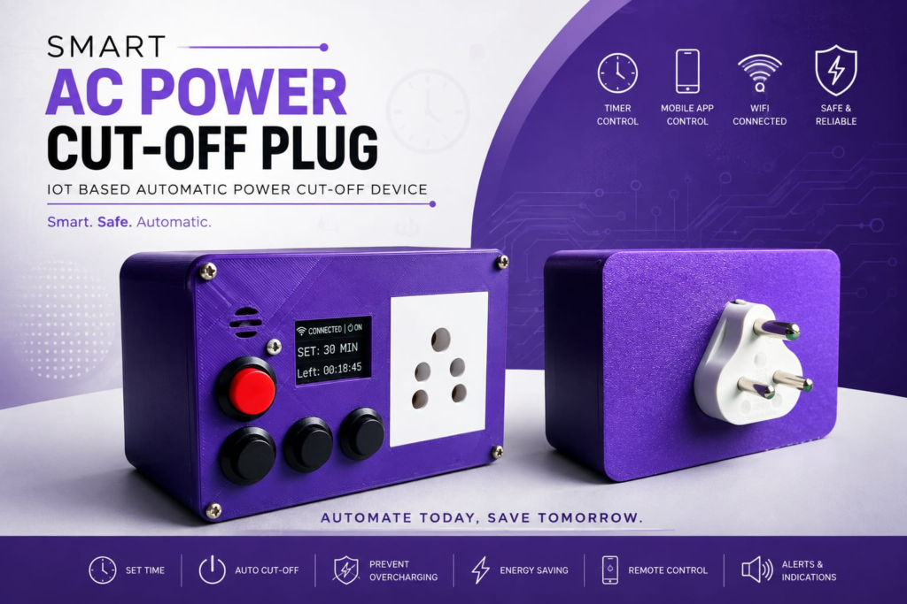
The Smart Cutoff Plug is an IoT-based power control device designed to automatically switch OFF the AC power after a selected period of time. I developed this project using the XIAO ESP32-C3, OLED display, relay, push buttons, LEDs, and buzzer to control and monitor the connected electrical load.
The system allows the user to select a preset or custom timer and start or stop the power manually. It also supports Blynk IoT control, where the user can monitor the timer, control the relay, and set scheduled operations through a mobile app.
The main purpose of this project is to provide a simple and convenient way to control charging or other AC loads without keeping the power ON for longer than required.
Problem Statement
Many times, mobile phones and other devices are left connected to the charger even after the required charging time is completed. The charger continues to remain connected to the AC power supply, which is not always necessary.
Charging the device for a longer time even after the battery is fully charged can generate unnecessary heat and charging stress, which may affect the battery’s health and lifespan over time.
I wanted to develop a simple device that could automatically switch OFF the AC supply after a selected time. The device should also be easy to control using physical buttons and a mobile application.
Proposed Solution
To solve this problem, I developed the Smart Cutoff Plug using the XIAO ESP32-C3 as the main controller. A relay is used to control the AC power, while the OLED display shows the selected time and remaining countdown.
The device can be operated using physical buttons as well as the Blynk IoT application. After the selected time is completed, the XIAO ESP32-C3 automatically turns OFF the relay and gives a completion indication using the LED and buzzer.
Key Features
- 30-minute, 1-hour and 2-hour preset timers
- Custom timer through Blynk
- Manual Start/Stop control
- Blynk IoT control
- OLED countdown display
- Automatic AC power cutoff
- RTC-based weekly scheduling
- Red and green status LEDs
- Completion buzzer
- Buzzer mute option
- OLED sleep mode
Working Principle
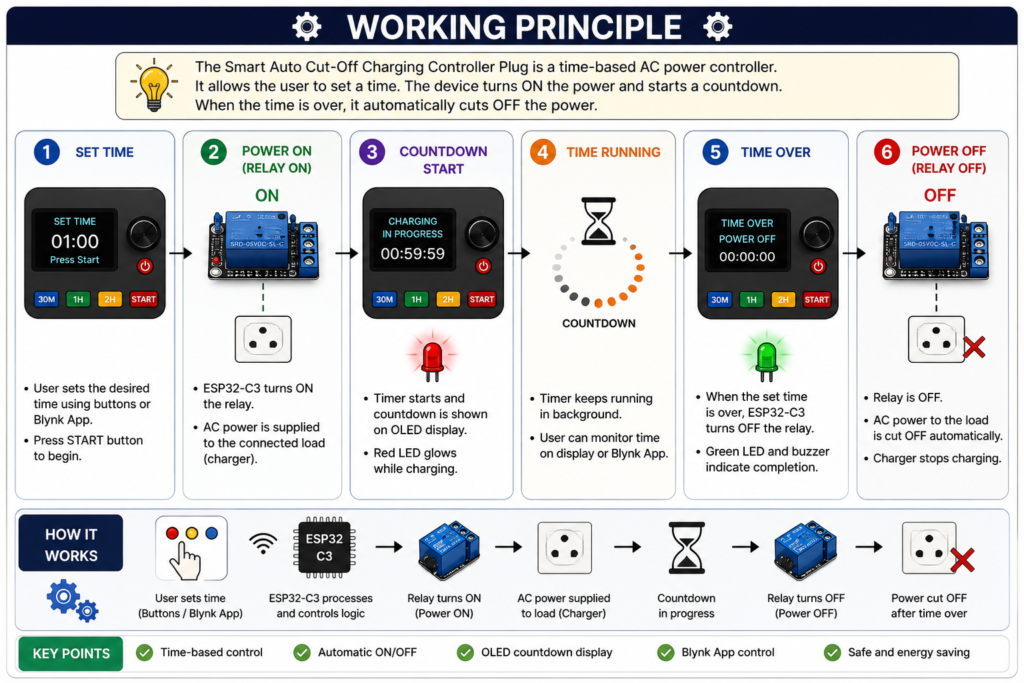
The Smart Cutoff Plug works by controlling the AC power supplied to a connected device using a relay. The user can select a preset timer using the physical buttons or set a custom timer through the Blynk app.
When the charging starts, the relay turns ON and the OLED displays the remaining time. The ESP32-C3 continuously runs the countdown using millis() without blocking the other functions.
When the timer reaches 00:00, the relay automatically turns OFF and the AC supply to the connected device is cut off. The red LED turns OFF, the green LED indicates completion, and the buzzer plays a short completion chime. The system can also perform automatic cutoff according to the RTC-based schedule set through Blynk.
Block Diagram
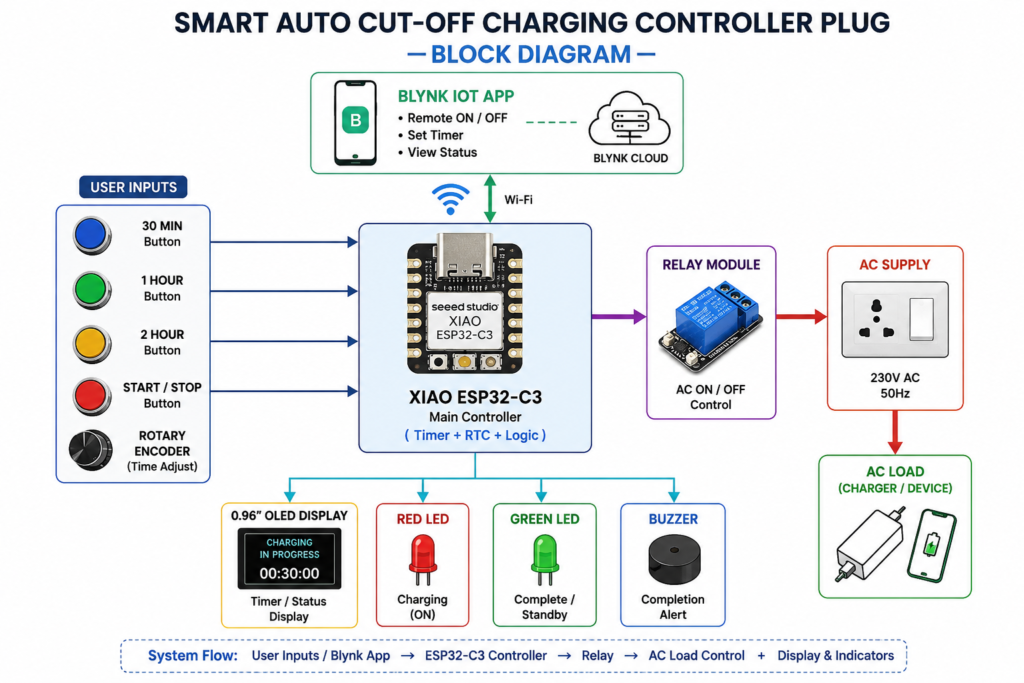
The Smart Cutoff Plug is built around the XIAO ESP32-C3, which acts as the main controller. It receives inputs from the physical push buttons and the Blynk IoT app. Based on these inputs, the ESP32-C3 controls the relay, OLED display, LEDs, and buzzer.
The basic system flow is:
Push Buttons / Blynk App → XIAO ESP32-C3 → Relay → AC Load
The ESP32-C3 also sends information to the OLED display and controls the Red LED, Green LED, and Buzzer for status indication.
Expected Outcome
The expected outcome of this project is to develop a compact and working Smart Cutoff Plug that can control an AC load for a selected period of time and automatically switch it OFF when the timer is completed.
The final device should work through both physical controls and the Blynk mobile application, show the countdown on the OLED display, provide completion alerts, and fit all the electronics properly inside the 3D-printed enclosure.
Project Development – Step by Step
After deciding the idea and basic requirements of the Smart Cutoff Plug, I started developing the project step by step. I first tested the electronics on a breadboard and worked on the code before moving towards the final PCB and 3D-printed enclosure.
The complete development process was done in the following stages:
Research → Components Ordering → Breadboard Testing → Coding → Debugging → Blynk Integration → AC Testing → PCB Design → PCB Milling → PCB Testing → 3D Design → 3D Printing → Assembly → Final Testing
Step 1 – Research
I started the project by researching how a timer-based automatic power cutoff system could be made. I looked at different microcontrollers, displays, relays, buttons, and IoT options that could be used for the project.
After comparing the requirements, I decided to use the XIAO ESP32-C3 because it has built-in Wi-Fi and is small enough to fit inside a compact plug enclosure. I also planned the basic features such as timer presets, OLED countdown, relay control, physical buttons, and Blynk app control.
Step 2 – Components Ordering
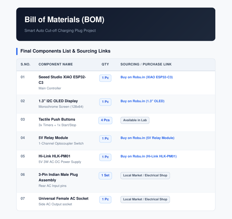
After completing the initial research, I finalized the components required for the project and ordered them. I selected the components according to the planned circuit and the functions I wanted to add to the Smart Cutoff Plug.
The main components included the XIAO ESP32-C3, OLED display, relay module, push buttons, LEDs, buzzer, and other required wiring and connectors.
Step 3 – Breadboard Testing
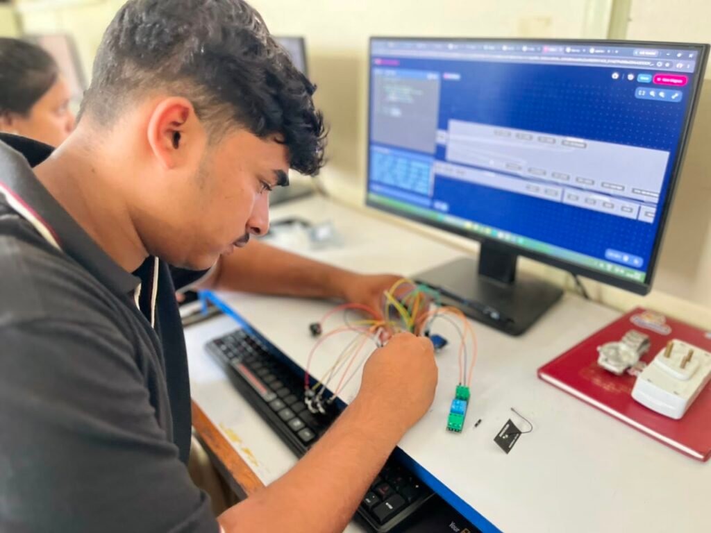
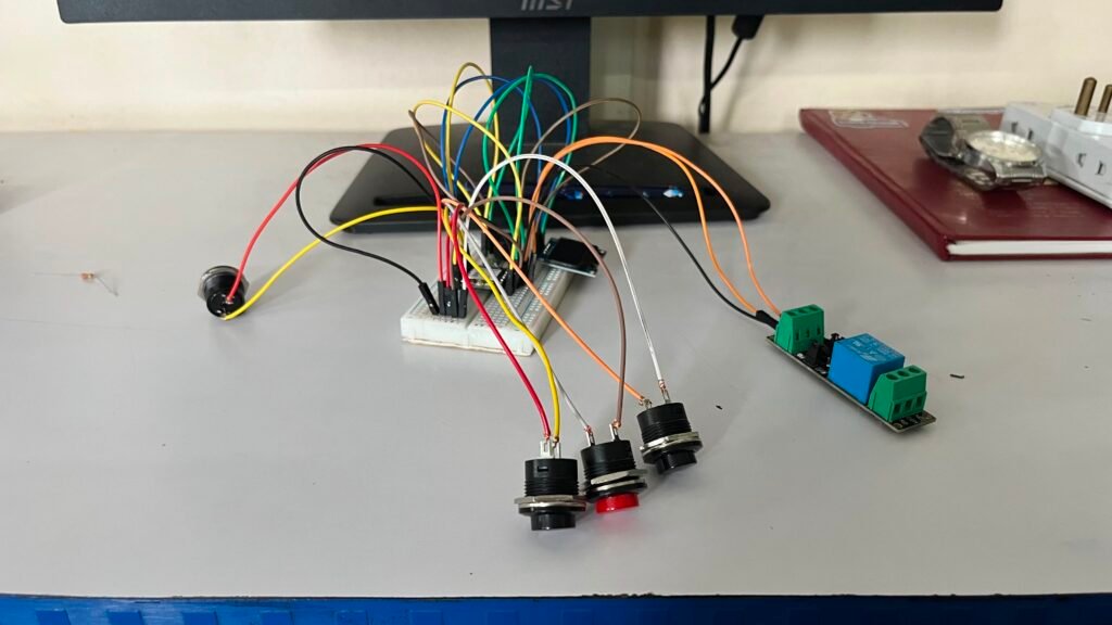
After receiving all the components, I started testing the project on a breadboard. I connected the XIAO ESP32-C3 with the OLED display, relay, push buttons, LEDs, and buzzer according to the planned connections.
I tested the components one by one first and then combined them into one circuit. This helped me check whether all the components were working properly before moving to the PCB stage.
| Component | XIAO ESP32-C3 Pin |
|---|---|
| OLED SDA | D4 |
| OLED SCL | D5 |
| Buzzer | D6 |
| Green LED | D8 |
| Red LED | D9 |
| Relay | D10 |
| 30-Min Button | D0 |
| 1-Hour Button | D1 |
| 2-Hour Button | D2 |
| Start/Stop Button | D3 |
Step 4 – Initial Coding and Testing
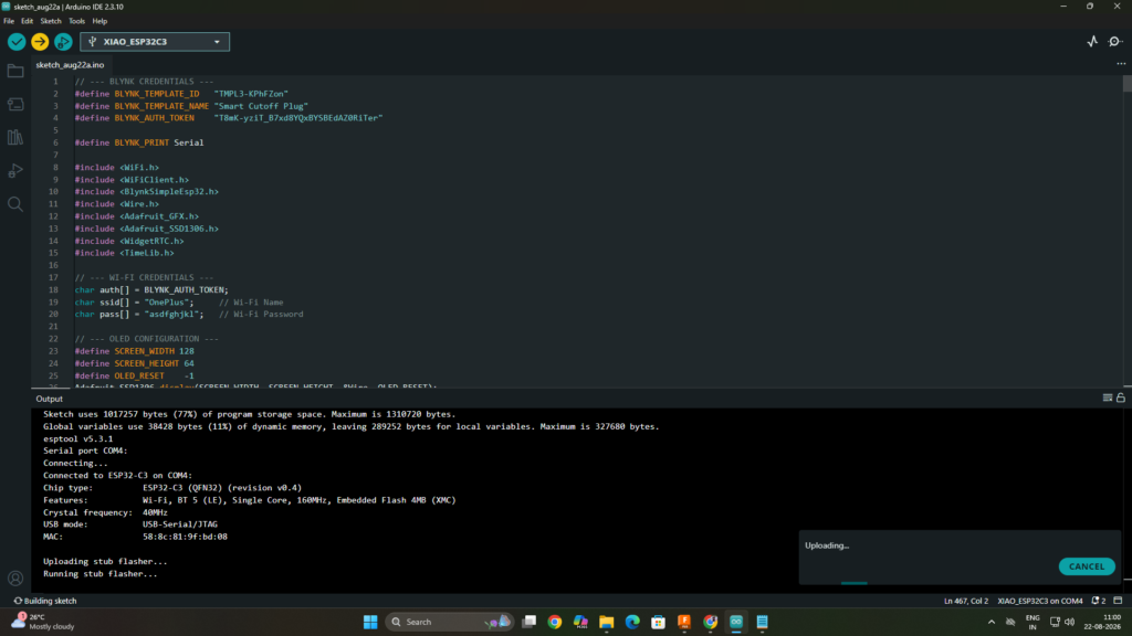
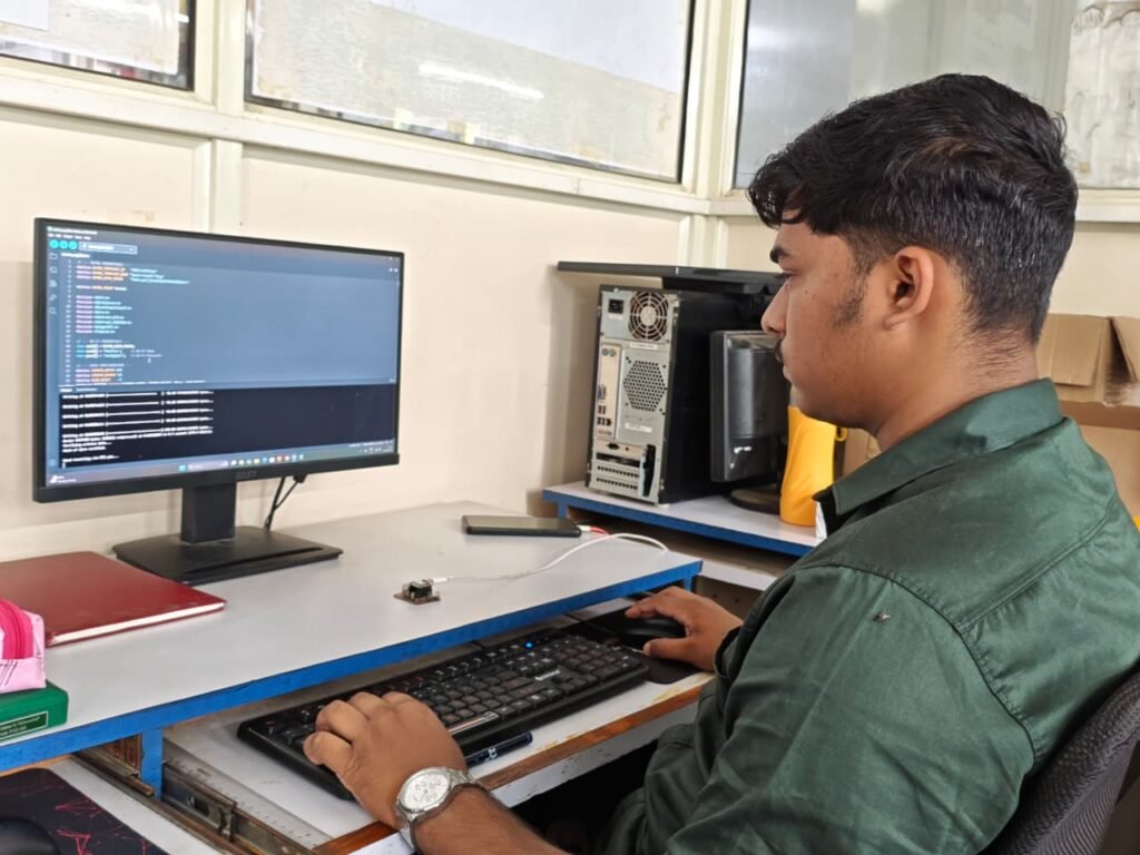
After completing the basic breadboard connections, I started working on the firmware for the XIAO ESP32-C3. I uploaded the code using Arduino IDE and tested the main functions such as button input, relay control, OLED display, LEDs, buzzer, and timer operation.
At this stage, the main goal was to make sure that the hardware and code were communicating correctly. I tested each function and checked the output on the actual components.
Step 5 – Final Code and Firmware
After testing the individual components, I modified the code according to the required functions of the project. I added the timer presets, Start/Stop control, OLED countdown, relay control, LED indications, buzzer alert, and other required functions.
After making the required changes and testing them, I uploaded the final firmware to the XIAO ESP32-C3. This version was then used for the further Blynk integration and testing of the complete system.
This is the final complete code used for the Smart Cutoff Plug.
// --- BLYNK CREDENTIALS ---
#define BLYNK_TEMPLATE_ID   "TMPL3-KPhFZon"
#define BLYNK_TEMPLATE_NAME "Smart Cutoff Plug"
#define BLYNK_AUTH_TOKEN    "T8mK-yziT_B7xd8YQxBYSBEdAZ0RiTer"

#define BLYNK_PRINT Serial

#include <WiFi.h>
#include <WiFiClient.h>
#include <BlynkSimpleEsp32.h>
#include <Wire.h>
#include <Adafruit_GFX.h>
#include <Adafruit_SSD1306.h>
#include <WidgetRTC.h>
#include <TimeLib.h>

// --- WI-FI CREDENTIALS ---
char auth[] = BLYNK_AUTH_TOKEN;
char ssid[] = "Your Wifi Name";     // Wi-Fi Name
char pass[] = "Wifi Password";   // Wi-Fi Password

// --- OLED CONFIGURATION ---
#define SCREEN_WIDTH 128
#define SCREEN_HEIGHT 64
#define OLED_RESET    -1
Adafruit_SSD1306 display(SCREEN_WIDTH, SCREEN_HEIGHT, &Wire, OLED_RESET);

WidgetRTC rtc;
BlynkTimer blynkTimer;

// --- HARDWARE PIN MAPPING (XIAO ESP32-C3) ---
#define BTN_30M   D0
#define BTN_1H    D1
#define BTN_2H    D2
#define BTN_START D3
#define BUZZER    D6
#define LED_RED   D9
#define LED_GREEN D8
#define RELAY_PIN D10

// --- SYSTEM VARIABLES ---
unsigned long timerDuration = 0;
unsigned long timerStartTime = 0;
bool isTimerRunning = false;

bool isMuted = false;
bool isOledSleep = false;

int schedStartHour = -1;
int schedStartMin = -1;
int schedStopHour = -1;
int schedStopMin = -1;
unsigned long schedDuration = 0;

bool isSchedActiveToday = false;
bool hasStartTriggeredThisMinute = false;
bool hasStopTriggeredThisMinute = false;

bool isGreenBlinking = false;
int greenBlinkCount = 0;
unsigned long lastGreenBlinkTime = 0;
bool isGreenAutoOffActive = false;
unsigned long greenAutoOffStartTime = 0;

unsigned long lastConnectAttempt = 0;

void updateOLED(String line1, String line2);
void startTimer();
void stopTimer(bool completed);
void playClickBeep();
void playTicTicAlert();
void checkSchedule();
void handleGreenLedLogic();

void setup() {
  Serial.begin(115200);

  pinMode(BTN_30M, INPUT_PULLUP);
  pinMode(BTN_1H, INPUT_PULLUP);
  pinMode(BTN_2H, INPUT_PULLUP);
  pinMode(BTN_START, INPUT_PULLUP);

  pinMode(RELAY_PIN, OUTPUT);
  pinMode(BUZZER, OUTPUT);
  pinMode(LED_RED, OUTPUT);
  pinMode(LED_GREEN, OUTPUT);

  digitalWrite(RELAY_PIN, LOW);
  digitalWrite(LED_RED, LOW);
  digitalWrite(LED_GREEN, LOW);
  digitalWrite(BUZZER, LOW);

  Wire.begin(D4, D5);
  Wire.setClock(400000);

  if(display.begin(SSD1306_SWITCHCAPVCC, 0x3C)) {
    display.clearDisplay();
    display.setTextColor(SSD1306_WHITE);
    display.setTextSize(1);
    display.setCursor(10, 10);
    display.println(F("SMART CUTOFF PLUG"));
    display.setTextSize(2);
    display.setCursor(10, 35);
    display.println(F("READY!"));
    display.display();
    delay(1000);
  }

  WiFi.mode(WIFI_STA);
  WiFi.begin(ssid, pass);

  Blynk.config(auth, "blynk.cloud", 8080);
  rtc.begin();

  blynkTimer.setInterval(1000L, checkSchedule);
  isOledSleep = false;

  updateOLED("SMART PLUG", "READY");
}

BLYNK_CONNECTED() {
  rtc.begin();
  Blynk.sendInternal("utc", "time");
  Blynk.syncVirtual(V4);
}

void loop() {
  if (WiFi.status() == WL_CONNECTED) {
    if (!Blynk.connected() && (millis() - lastConnectAttempt > 10000)) {
      lastConnectAttempt = millis();
      Blynk.connect(1000);
    }
  }

  if (Blynk.connected()) {
    Blynk.run();
  }

  blynkTimer.run();
  handleGreenLedLogic();

  if (digitalRead(BTN_30M) == LOW) {
    playClickBeep();
    timerDuration = 1800;
    updateOLED("PRESET", "30 MINS");
    if (Blynk.connected()) Blynk.virtualWrite(V1, "30:00");
    delay(300);
  }

  if (digitalRead(BTN_1H) == LOW) {
    playClickBeep();
    timerDuration = 3600;
    updateOLED("PRESET", "1 HOUR");
    if (Blynk.connected()) Blynk.virtualWrite(V1, "60:00");
    delay(300);
  }

  if (digitalRead(BTN_2H) == LOW) {
    playClickBeep();
    timerDuration = 7200;
    updateOLED("PRESET", "2 HOURS");
    if (Blynk.connected()) Blynk.virtualWrite(V1, "120:00");
    delay(300);
  }

  if (digitalRead(BTN_START) == LOW) {
    playClickBeep();
    if (!isTimerRunning && timerDuration > 0) {
      startTimer();
    } else if (isTimerRunning) {
      stopTimer(false);
    }
    delay(300);
  }

  if (isTimerRunning) {
    unsigned long elapsed = (millis() - timerStartTime) / 1000;

    if (elapsed >= timerDuration) {
      stopTimer(true);
    } else {
      unsigned long remaining = timerDuration - elapsed;
      int mins = remaining / 60;
      int secs = remaining % 60;

      if (!isOledSleep) {
        display.clearDisplay();
        display.setTextColor(SSD1306_WHITE);
        display.setTextSize(1);
        display.setCursor(0, 5);
        display.println("CHARGING...");

        // Large readable timer text
        display.setTextSize(3);
        display.setCursor(18, 28);
        display.printf("%02d:%02d", mins, secs);
        display.display();
      }

      if (Blynk.connected()) {
        char timeStr[10];
        sprintf(timeStr, "%02d:%02d", mins, secs);
        Blynk.virtualWrite(V1, timeStr);
      }
    }
  }
}

void handleGreenLedLogic() {
  if (isGreenBlinking) {
    if (millis() - lastGreenBlinkTime >= 250) {
      lastGreenBlinkTime = millis();
      digitalWrite(LED_GREEN, !digitalRead(LED_GREEN));
      greenBlinkCount++;

      if (greenBlinkCount >= 8) {
        isGreenBlinking = false;
        digitalWrite(LED_GREEN, HIGH);
        isGreenAutoOffActive = true;
        greenAutoOffStartTime = millis();
      }
    }
  }

  if (isGreenAutoOffActive) {
    if (millis() - greenAutoOffStartTime >= 30000) {
      digitalWrite(LED_GREEN, LOW);
      isGreenAutoOffActive = false;
    }
  }
}

void checkSchedule() {
  if (year() == 1970) return;

  if (minute() != schedStartMin) hasStartTriggeredThisMinute = false;
  if (minute() != schedStopMin)  hasStopTriggeredThisMinute = false;

  if (!isSchedActiveToday) return;

  if (schedStartHour >= 0 && schedStartMin >= 0 && !hasStartTriggeredThisMinute) {
    if (hour() == schedStartHour && minute() == schedStartMin) {
      if (!isTimerRunning) {
        hasStartTriggeredThisMinute = true;
        timerDuration = (schedDuration > 0) ? schedDuration : 3600;
        startTimer();
        updateOLED("SCHEDULE", "STARTED");
      }
    }
  }

  if (schedStopHour >= 0 && schedStopMin >= 0 && !hasStopTriggeredThisMinute) {
    if (hour() == schedStopHour && minute() == schedStopMin) {
      if (isTimerRunning) {
        hasStopTriggeredThisMinute = true;
        stopTimer(true);
        updateOLED("SCHEDULE", "STOPPED");
      }
    }
  }
}

BLYNK_WRITE(V4) {
  TimeInputParam p(param);

  if (p.hasStartTime()) {
    schedStartHour = p.getStartHour();
    schedStartMin = p.getStartMinute();
  } else {
    schedStartHour = -1;
    schedStartMin = -1;
  }

  if (p.hasStopTime()) {
    schedStopHour = p.getStopHour();
    schedStopMin = p.getStopMinute();
  } else {
    schedStopHour = -1;
    schedStopMin = -1;
  }

  if (schedStartHour >= 0 && schedStopHour >= 0) {
    long startSec = (long)schedStartHour * 3600 + schedStartMin * 60;
    long stopSec  = (long)schedStopHour * 3600 + schedStopMin * 60;

    if (stopSec > startSec) {
      schedDuration = stopSec - startSec;
    } else {
      schedDuration = (86400L - startSec) + stopSec;
    }
  } else {
    schedDuration = 0;
  }

  int currentDay = weekday();
  int blynkDayIdx = (currentDay == 1) ? 7 : (currentDay - 1);
  isSchedActiveToday = p.isWeekdaySelected(blynkDayIdx);

  hasStartTriggeredThisMinute = false;
  hasStopTriggeredThisMinute = false;
}

BLYNK_WRITE(V0) {
  int value = param.asInt();
  if (value == 1 && !isTimerRunning) {
    if (timerDuration == 0) timerDuration = 1800;
    startTimer();
  } else if (value == 0 && isTimerRunning) {
    stopTimer(false);
  }
}

BLYNK_WRITE(V2) {
  int option = param.asInt();
  if (!isTimerRunning) {
    if (option == 1) { timerDuration = 1800; updateOLED("PRESET", "30 MINS"); }
    else if (option == 2) { timerDuration = 3600; updateOLED("PRESET", "1 HOUR"); }
    else if (option == 3) { timerDuration = 7200; updateOLED("PRESET", "2 HOURS"); }
  }
}

BLYNK_WRITE(V5) {
  isMuted = (param.asInt() == 1);
}

BLYNK_WRITE(V6) {
  isOledSleep = (param.asInt() == 1);
  if (isOledSleep) {
    display.clearDisplay();
    display.display();
  } else {
    updateOLED("DISPLAY", "ACTIVE");
  }
}

BLYNK_WRITE(V7) {
  int customMins = param.asInt();
  if (!isTimerRunning && customMins > 0) {
    timerDuration = customMins * 60;
    String strMins = String(customMins) + " MINS";
    updateOLED("CUSTOM", strMins);

    char timeBuffer[10];
    sprintf(timeBuffer, "%02d:00", customMins);
    Blynk.virtualWrite(V1, timeBuffer);
  }
}

void startTimer() {
  isTimerRunning = true;
  timerStartTime = millis();

  isGreenBlinking = false;
  isGreenAutoOffActive = false;

  digitalWrite(RELAY_PIN, HIGH);
  digitalWrite(LED_RED, HIGH);
  digitalWrite(LED_GREEN, LOW);

  if (Blynk.connected()) {
    Blynk.virtualWrite(V0, 1);
    Blynk.virtualWrite(V3, "Charging ON");
  }
}

void stopTimer(bool completed) {
  isTimerRunning = false;
  timerDuration = 0;

  digitalWrite(RELAY_PIN, LOW);
  digitalWrite(LED_RED, LOW);

  if (completed) {
    isGreenBlinking = true;
    greenBlinkCount = 0;
    lastGreenBlinkTime = millis();
  } else {
    digitalWrite(LED_GREEN, LOW);
  }

  if (Blynk.connected()) {
    Blynk.virtualWrite(V0, 0);
    Blynk.virtualWrite(V1, "00:00");
    Blynk.virtualWrite(V3, completed ? "Charging Complete" : "Standby (OFF)");
  }

  updateOLED("DONE!", "CUT-OFF");

  if (completed) {
    if (Blynk.connected()) {
      Blynk.logEvent("charging_complete", "Charging Complete! Power cut off.");
    }
    if (!isMuted) {
      playTicTicAlert();
    }
  }
}

void playClickBeep() {
  if (!isMuted) {
    for (int i = 0; i < 80; i++) {
      digitalWrite(BUZZER, HIGH);
      delayMicroseconds(250);
      digitalWrite(BUZZER, LOW);
      delayMicroseconds(250);
    }
  }
}

void playTicTicAlert() {
  if (!isMuted) {
    for (int cycle = 0; cycle < 10; cycle++) {
      for (int i = 0; i < 100; i++) {
        digitalWrite(BUZZER, HIGH);
        delayMicroseconds(500);
        digitalWrite(BUZZER, LOW);
        delayMicroseconds(500);
      }
      delay(100);
    }
  }
}

// Larger, high-visibility text rendering
void updateOLED(String line1, String line2) {
  if (isOledSleep) return;

  display.clearDisplay();
  display.setTextColor(SSD1306_WHITE);

  // Header Text
  display.setTextSize(1);
  display.setCursor(0, 5);
  display.println(line1);

  // Main Status Text (Size 2 - Big & Bold)
  display.setTextSize(2);
  display.setCursor(0, 30);
  display.println(line2);

  display.display();
}
Step 6 – Blynk IoT Integration
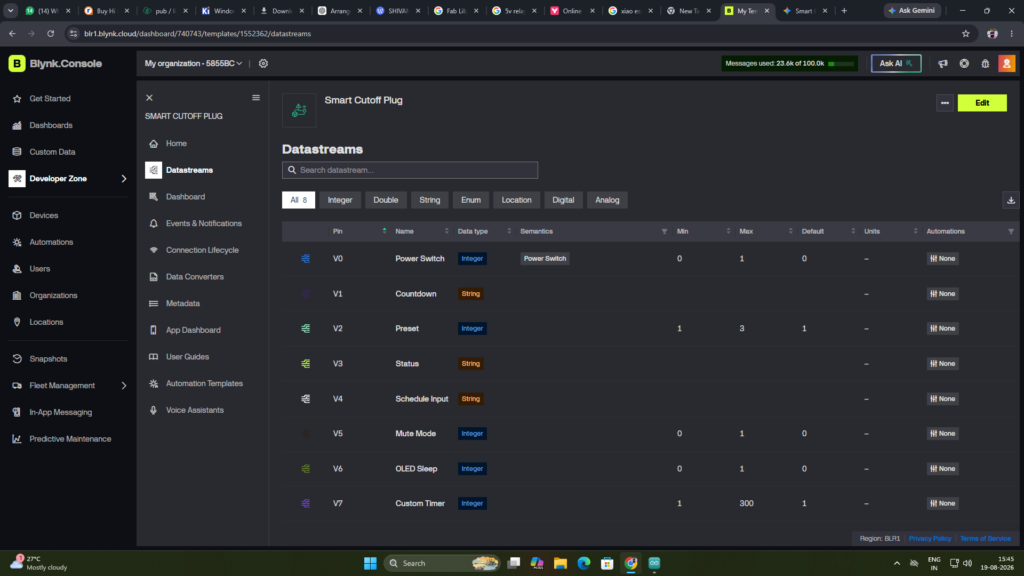
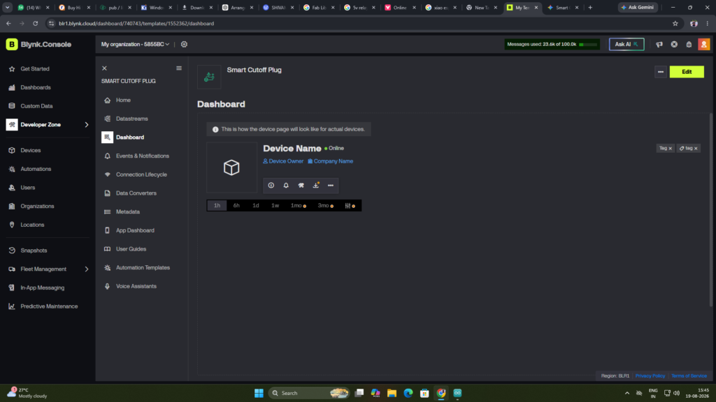
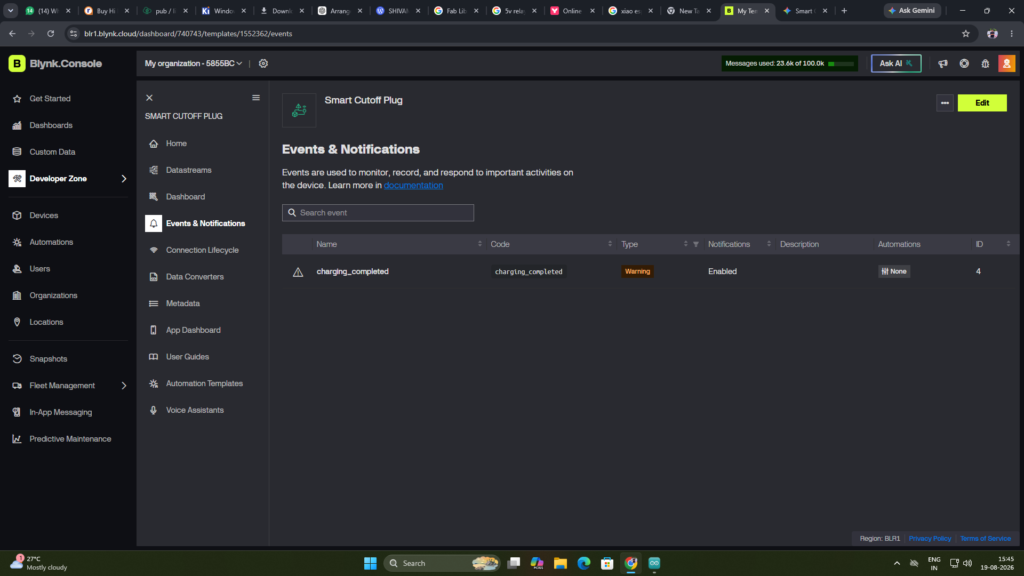
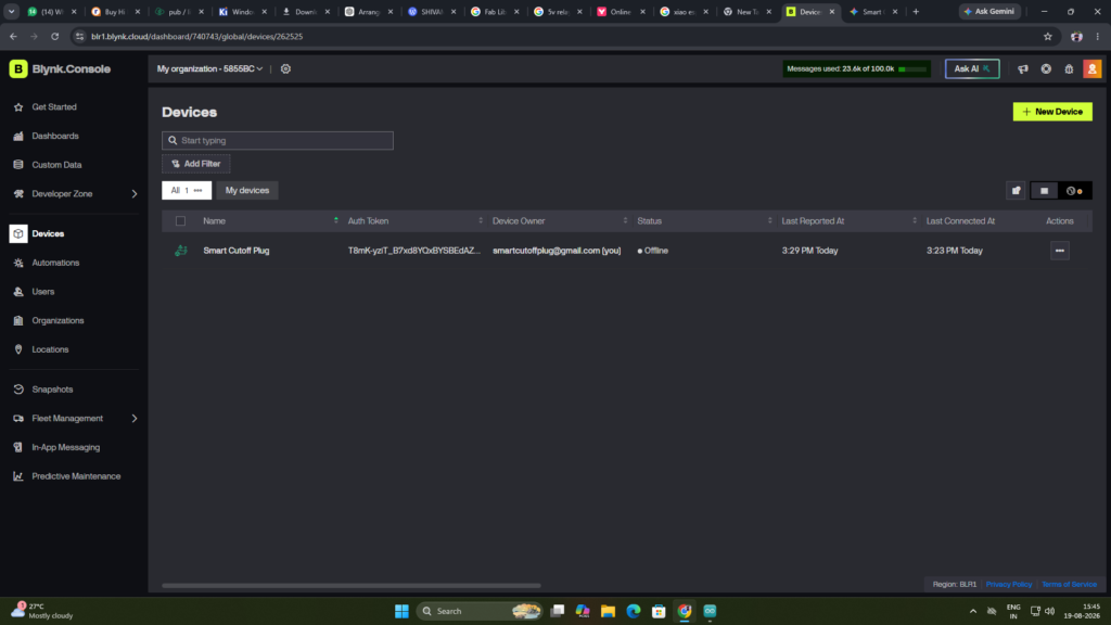
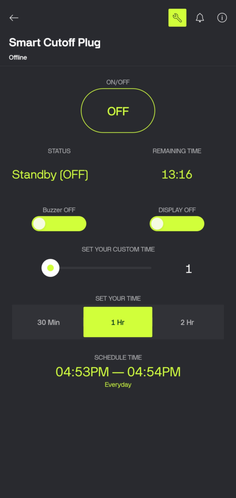
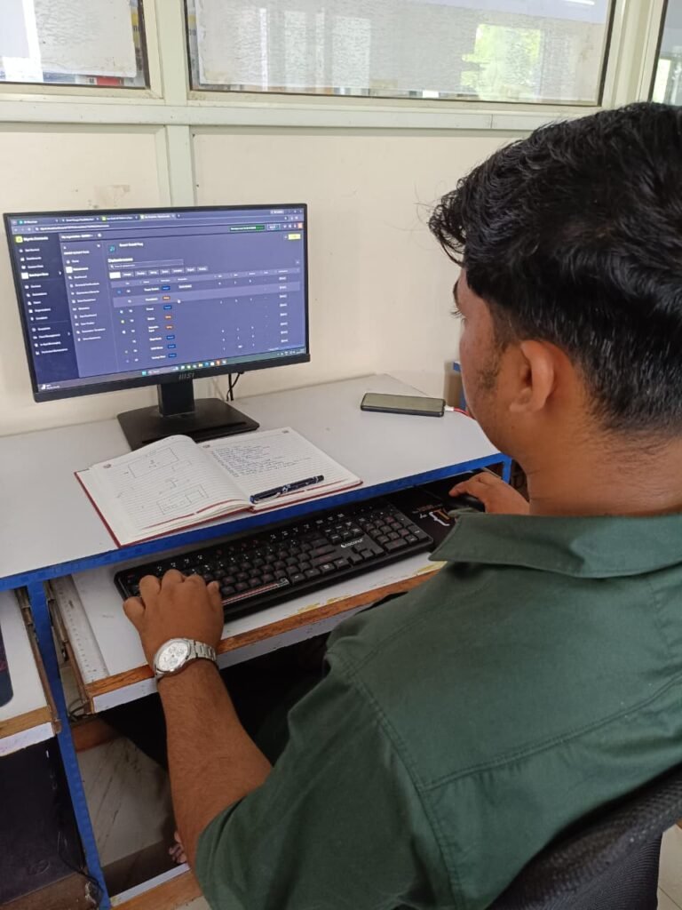
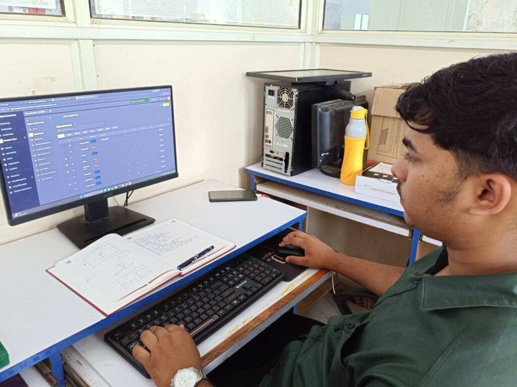
After the hardware and final code were working properly, I started integrating the project with the Blynk IoT platform. I created the Blynk template and device, and then configured the required datastreams and virtual pins for controlling and monitoring the Smart Cutoff Plug.
I added the required controls in the Blynk app for relay ON/OFF, timer presets, custom timer, countdown display, system status, RTC scheduling, buzzer mute, and OLED sleep mode. After completing the setup, I connected the ESP32-C3 to Blynk and tested the controls with the actual hardware.
Step 7 – AC Load Testing
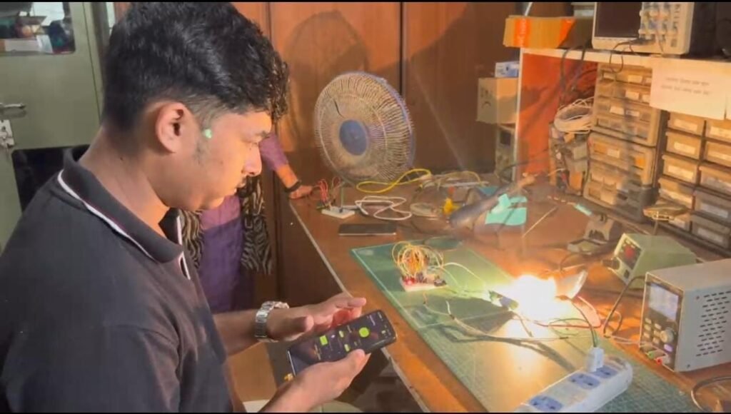
After completing the Blynk setup, I tested the Smart Cutoff Plug with an actual AC supply. For the initial load testing, I used a bulb to check the relay switching and automatic power cut-off.
I tested the system by turning the relay ON, running the selected timer, and checking whether the bulb switched OFF automatically when the timer was completed. This confirmed that the controller was able to control the AC load as expected.
Testing Result:
The relay successfully switched the AC load ON and OFF according to the timer operation.
Step 8 – PCB Design
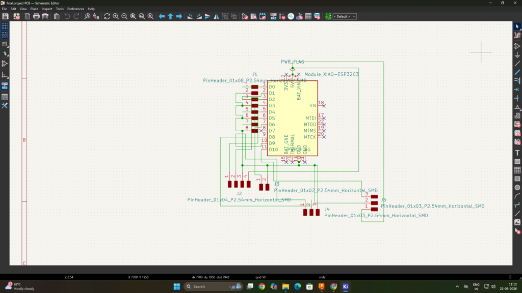
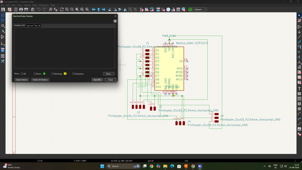
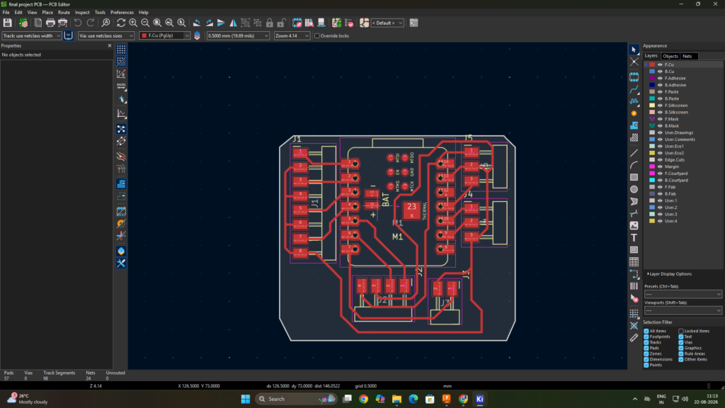
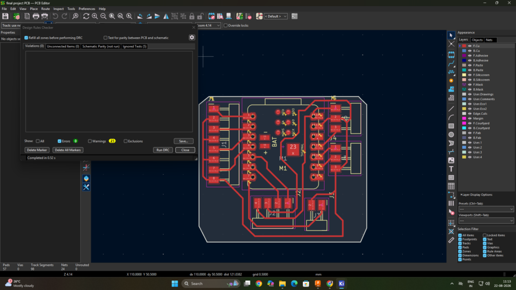
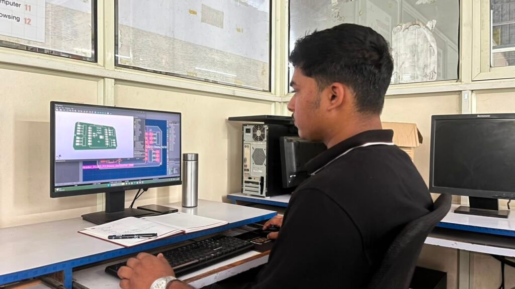
After successfully testing the complete system on the breadboard and with the AC load, I started designing the final PCB using KiCad. I created the circuit schematic and then designed the PCB layout according to the tested connections.
After completing the PCB layout, I used ERC (Electrical Rules Check) to check the schematic for electrical connection errors. I also used DRC (Design Rules Check) to check the PCB layout for design and routing errors before fabrication.
After completing these checks, I prepared the final PCB design for milling.
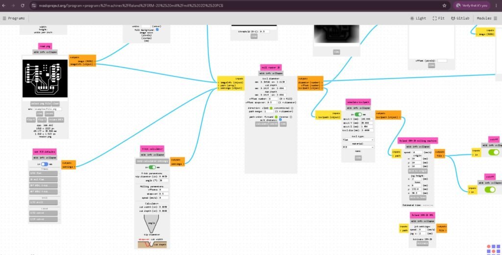
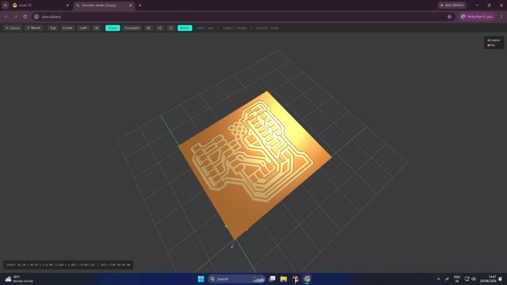
Step 9 – PCB Milling
After completing the PCB design and checking it using ERC and DRC, I used the final KiCad design to fabricate the PCB using a milling machine.
The milling process removed the unwanted copper from the PCB and created the required tracks and connection areas. After milling was completed, I cleaned the PCB and checked the tracks to make sure the board was ready for the next stage.
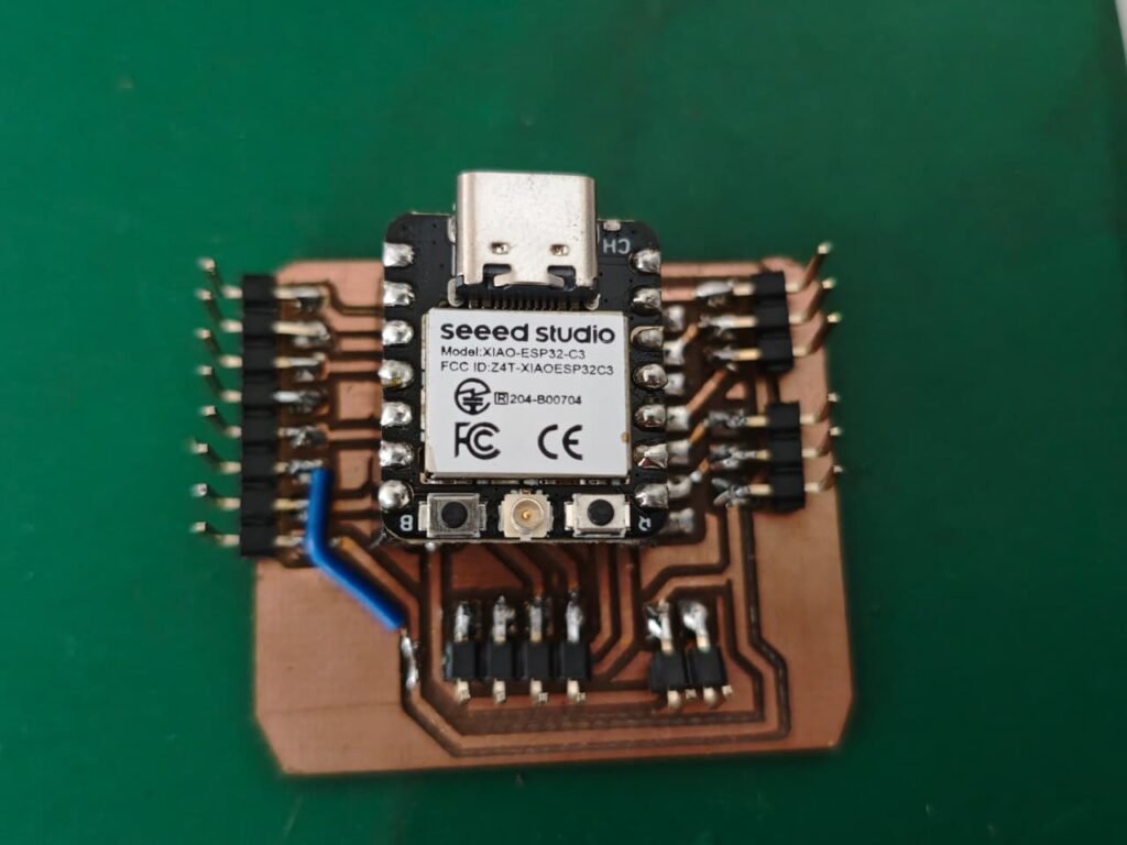
Step 10 – Connector Soldering
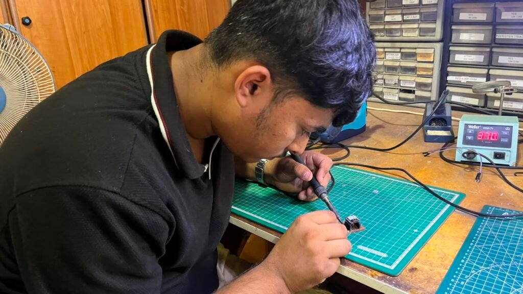
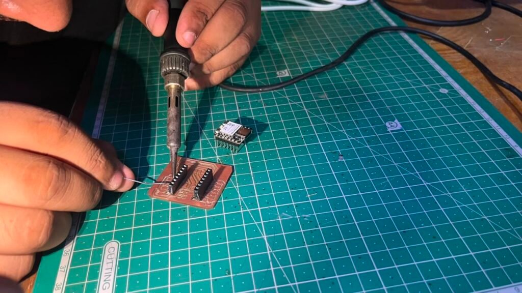
After the PCB milling was completed, I soldered the required connectors and terminals onto the PCB. These connectors were used to make the connections between the PCB and the different components of the Smart Cutoff Plug.
After soldering, I checked the solder joints and made sure there were no unwanted connections or loose joints before moving to the testing stage.
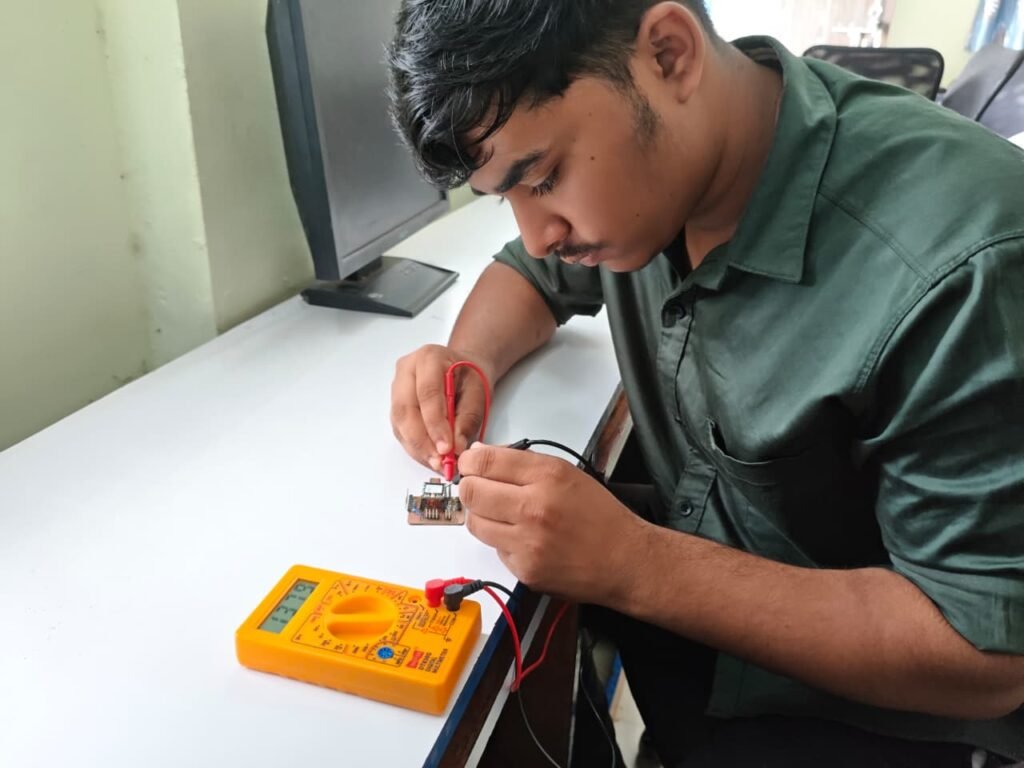
Step 11 – PCB Testing
After soldering the connectors, I tested the PCB using a multimeter. I checked the continuity of the tracks and verified the important connections on the board before connecting the main components.
This step helped me identify any unwanted short circuits or connection problems on the PCB before powering and testing the complete circuit.
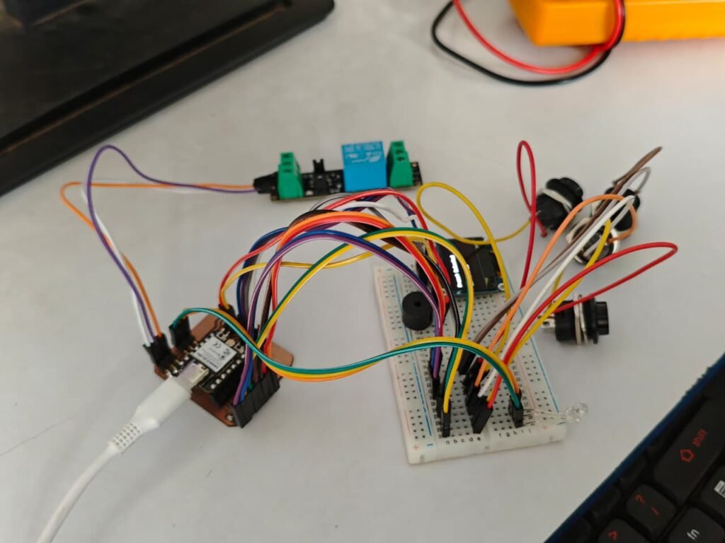
Step 12 – Connecting Components to the PCB
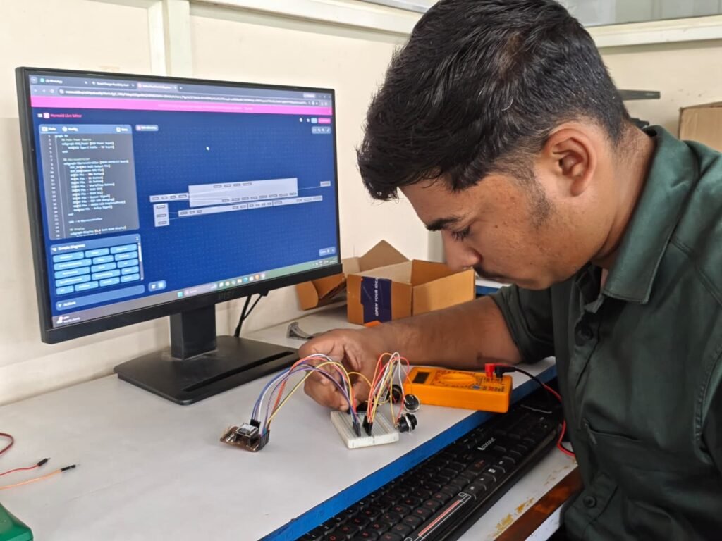
After checking the PCB with the multimeter, I connected the required components to the PCB. I connected the XIAO ESP32-C3, OLED display, relay, push buttons, LEDs, and buzzer according to the circuit design.
After making all the connections, I powered the system and tested the components again to make sure everything was working correctly on the PCB.
Step 13 – 3D Enclosure Design
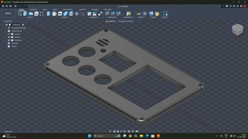
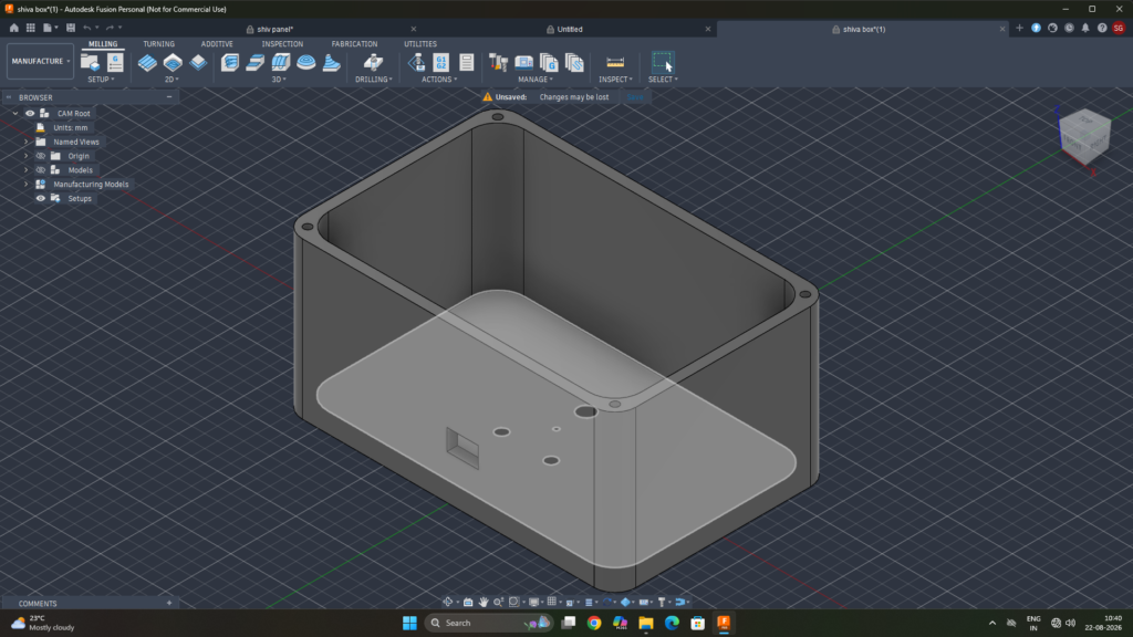
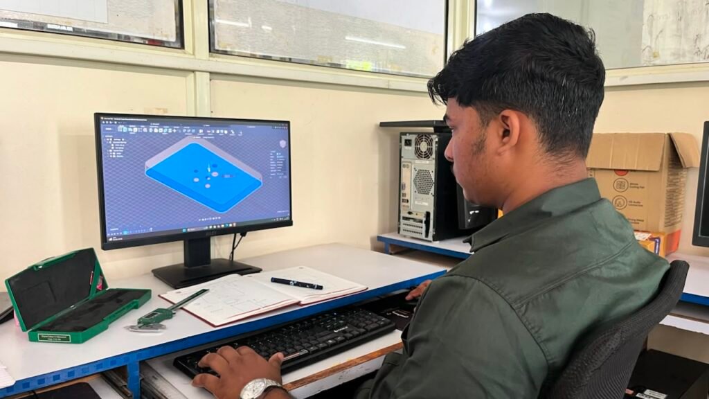
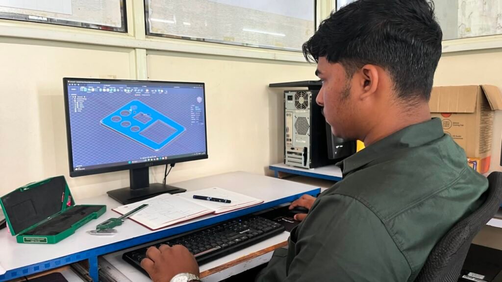
After completing the PCB and testing all the components, I started designing the enclosure for the Smart Cutoff Plug. I used Fusion 360 to create the 3D model according to the size and arrangement of the PCB and other components.
I added the required openings for the OLED display, push buttons, AC socket, and other parts so that all the components could fit properly inside the enclosure.
Step 14 – 3D Printing
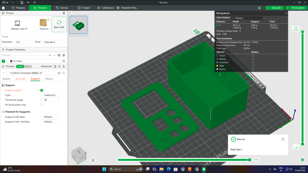
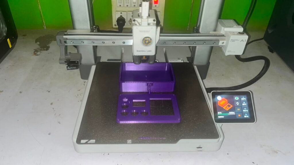
After completing the enclosure design in Fusion 360, I exported the 3D model and prepared it for printing using Bambu Studio. I used the Bambu Lab A1 3D printer to print the enclosure.
The final print used approximately 119 g of PLA+ filament and took around 3 hours 25 minutes to complete.
After printing, I checked the printed enclosure and made sure that the PCB, OLED, buttons, and other components could fit properly inside it.
Printing Details:
Print Time: 3 hours 25 minutes
Slicing Software: Bambu Studio
3D Printer: Bambu Lab A1
Material: PLA+
Filament Used: 119 g
Step 15 – Final Assembly
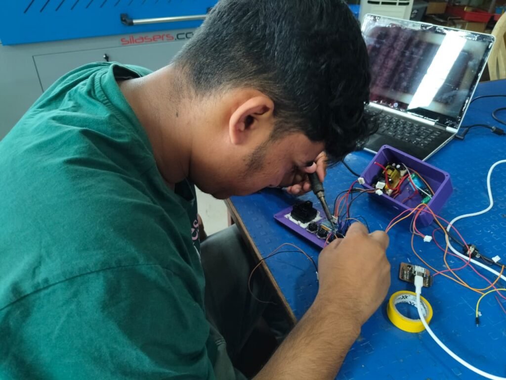
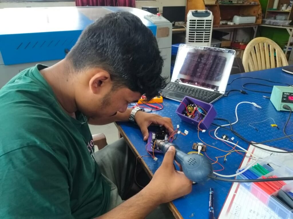
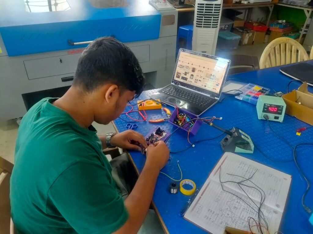
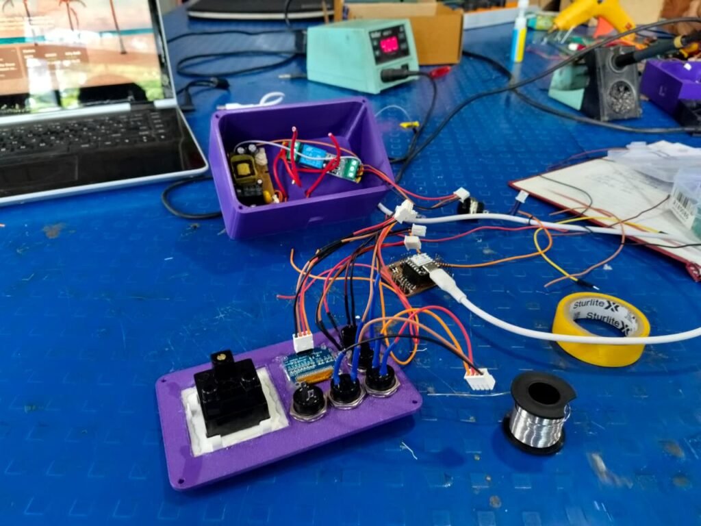
After the 3D-printed enclosure was ready, I started assembling the complete Smart Cutoff Plug. I fitted the PCB and all the required components inside the enclosure and arranged them according to the enclosure design.
The OLED display, push buttons, relay, LEDs, buzzer, and other connections were positioned properly so that the device could be used easily from the outside. After fitting all the components, I closed the enclosure and prepared the device for final testing.
Step 16 – Final Testing
After completing the assembly, I performed the final testing of the Smart Cutoff Plug. I checked the physical buttons, OLED countdown, relay switching, LEDs, buzzer, Blynk control, and timer operation.
I also checked the complete device with the AC load to make sure that the system was working properly after being assembled inside the enclosure.
The final testing confirmed that the Smart Cutoff Plug was able to perform the required functions as planned.bd268
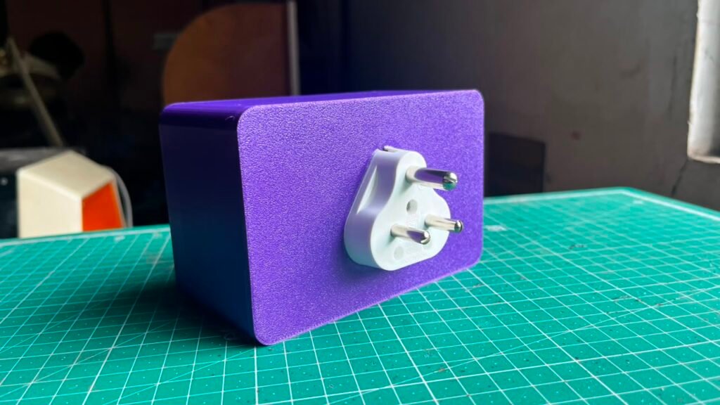
Final Working
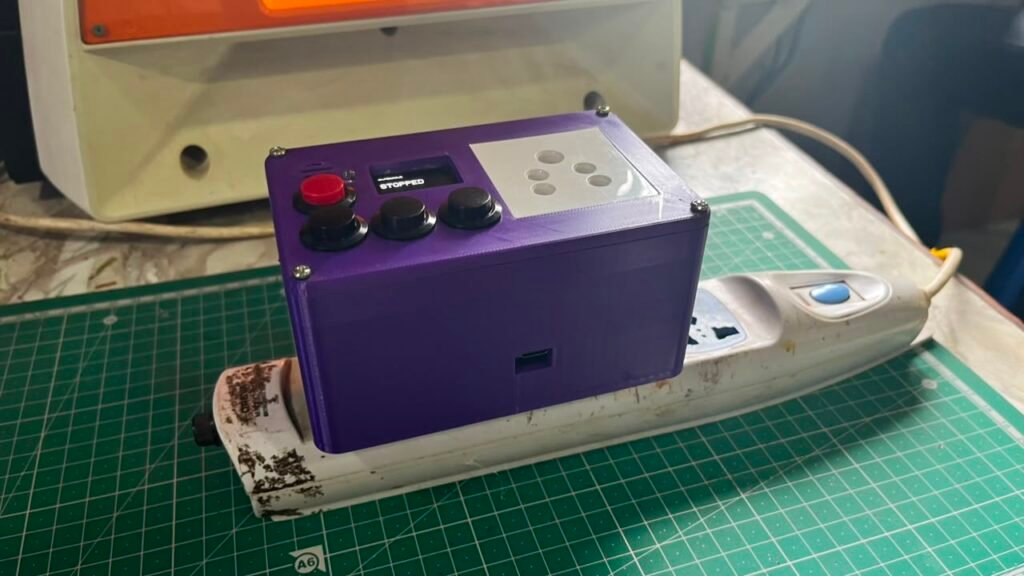
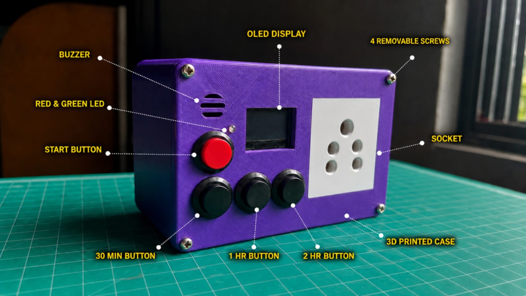
After completing the final testing, the Smart Cutoff Plug was ready as a complete working device. The user can select a timer using the physical buttons or Blynk app and start the charging process.
During charging, the relay remains ON and the OLED shows the remaining time. When the timer reaches zero, the relay automatically switches OFF and the connected AC load is disconnected. The LEDs and buzzer provide the completion indication.
The Blynk app also allows remote control, custom timer settings, status monitoring, and scheduled operation of the device.
Testing & Results
The final Smart Cutoff Plug was tested after completing the PCB assembly and enclosure assembly. Different functions of the device were checked to make sure that the hardware and software were working together properly.
The main tests included:
- Timer preset operation
- Manual Start/Stop
- Relay ON/OFF operation
- OLED countdown
- Blynk control
- Custom timer
- RTC schedule
- LED indications
- Buzzer alert
- Automatic power cut-off
The tests showed that the Smart Cutoff Plug was able to perform the required operations and automatically cut off the connected AC load after the selected time.
Project Files
I have uploaded all the important project files in a Google Drive folder. The folder contains the KiCad PCB files, Gerber files, Fusion 360 design, STL files and other project-related files.
Project Files:
All Files Of The Smart Auto CutOff Project
Bill of Materials & Project Cost
The following table shows the approximate cost of the main components and materials used to build the Smart Cutoff Plug. The costing is based on the actual purchase prices and the material used during fabrication.
| Component / Material | Qty. | Unit Cost | Total |
|---|---|---|---|
| XIAO ESP32-C3 | 1 | ₹779 | ₹779 |
| 0.96″ OLED Display | 1 | ₹229 | ₹229 |
| 5V Relay Module | 1 | ₹89 | ₹89 |
| Active Buzzer | 1 | ₹19 | ₹19 |
| LEDs | 1 set | ₹5 | ₹5 |
| Push Buttons | 4 | ₹22 | ₹88 |
| PLA+ Filament | 119 g | ₹0.78/g | ₹92.82 |
| Connectors | 22 | ₹7 | ₹154 |
| AC-DC Converter | 1 | ₹150 | ₹150 |
| Total | ₹1,605.82 |
Approximate component and material cost: ₹1,606
Note: PCB fabrication, wires, resistors, AC plug/socket and other miscellaneous materials are not included in this calculation and can be added separately if required.
Challenges and Solutions
During the development of the Smart Cutoff Plug, I faced some challenges while testing the hardware and software. The project required multiple rounds of testing and code modification before all the functions worked together properly.
Some of the main challenges were:
- Code debugging: The code had to be modified multiple times during testing to get all functions working correctly.
- Blynk integration: Setting up the template, device, datastreams, and controls required testing and configuration.
- AC load testing: The relay and automatic cutoff had to be tested carefully with an actual AC load.
- PCB development: The PCB connections had to be checked using ERC, DRC, and a multimeter before connecting the components.
- Enclosure fitting: The 3D enclosure had to be designed according to the actual size and position of the PCB and components.
These challenges were solved through repeated testing, debugging, and making changes wherever required.
Conclusion
The Smart Cutoff Plug was successfully developed from an initial idea into a working IoT-based AC power control device. The project was developed step by step, starting with research and breadboard testing and then moving to firmware development, Blynk integration, AC load testing, PCB fabrication, 3D printing, and final assembly.
The final device can control the connected AC load using a timer, physical buttons, and the Blynk app. It also provides an OLED countdown, automatic cutoff, RTC scheduling, LED indications, and a buzzer alert.
Through this project, I worked on embedded programming, IoT, electronics prototyping, PCB design, PCB fabrication, 3D CAD design, 3D printing, and final hardware assembly.