JUNE FIRST WEEK
AIM
To design and analyze a finned-tube radiator capable of transferring heat from hot water to air and producing heated air suitable for drying applications.
BACKGROUND
Drying is one of the most widely used methods for preserving agricultural products. The efficiency of a drying system depends on its ability to remove moisture from the substrate. Which in turn depends on the airflow, air humidity, and air temperature. Vigyan Ashram is looking to build a system where hot water, either from Solar water heaters or biomass gasifiers, can be used as a heat source for drying applications. A radiator acts as a heat exchanger that transfers thermal energy from hot water to air, which in trun will act as drying media. Therefore, proper radiator design is essential for achieving energy-efficient and uniform drying.
INTRODUCTION
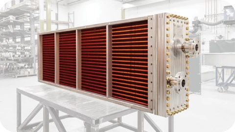
A radiator is a heat exchanger designed to transfer heat from a hot fluid to a colder fluid without direct contact. In drying, we envisage applications where hot water flows through tubes while ambient air passes over finned surfaces. Heat is transferred from the water to the tube walls, then through the fins, and finally to the air.
The use of fins significantly increases the available heat transfer area and arrangement of tubes breaks laminar resulting in higher thermal efficiency. The design of a radiator involves selecting appropriate tube dimensions, fin geometry, tube arrangement, and flow rates to achieve the desired outlet air temperature.
OBJECTIVES
- To understand the working principle of a radiator as a heat exchanger.
- To calculate the heat transfer rate required for air heating.
- To determine radiator dimensions such as tube length, tube diameter, fin spacing, and fin thickness to suit the objective no. 2
- Design and fabricate the said system
- To evaluate the effect of airflow and water flow rate on heat transfer performance.
- To optimize the radiator design for maximum thermal efficiency.
WORKING
The radiator functions as a heat exchanger between hot water and air. Hot water enters the radiator tubes at a high temperature (around 80–90°C) and flows through the tube network. Simultaneously, ambient air is forced across the finned tubes using a blower or fan.
As the hot water flows inside the tubes, heat is transferred to the tube walls by convection. The heat then conducts through the tube material and spreads into the attached fins. Because fins provide a much larger surface area than plain tubes, they significantly enhance heat transfer to the surrounding air.
The moving air absorbs this heat and its temperature increases before entering the drying chamber. Meanwhile, the water temperature decreases as it releases heat, typically leaving the radiator at 50–60°C.
For improved performance, tubes are often arranged in a staggered pattern. This arrangement increases air turbulence, improves contact between air and the heat transfer surfaces, and enhances overall heat transfer efficiency.
The heat transfer process occurs are:
- Convection from hot water to the inner tube surface.
- Conduction through the tube wall and fins.
- Convection from the outer finned surface to the airflow.
JUNE SECOND WEEK
Design Requirements and Parameters
Hot Water Side Parameters
- Inlet water temperature: 80–90°C
- Outlet water temperature: 50–60°C (???)
- Water flow rate: To be determined based on heat demand
- Working fluid: Water
- Operating pressure: As per system requirements
Air Side Parameters
- Inlet air temperature: Ambient temperature
- Desired outlet air temperature: Approximately 65°C
- Air flow rate: Depends on the rateof loss of moisture/drying rate
Geometrical Parameters
- Tube diameter
- Tube wall thickness
- Tube length
- Number of tubes
- Tube pitch
- Number of tube rows
- Fin thickness
- Fin spacing
- Fin height
Radiator Design Calculation
Step 1: Moisture Removal Requirement
Assume:
- Moisture to be removed = 40 kg
- Drying time = 6 hours
Moisture removal rate:
Step 2: Energy Required for Water Evaporation
Latent heat of vaporization of water:
Heat required:
Step 3: Include System Losses
Dryers experience losses due to:
- Wall losses
- Air leakage
- Tray heating
- Product heating
Assume:
Additional heat.
Step 4: Water Temperature Selection
Assume solar hot water or boiler water:
| Parameter | Value |
|---|---|
| Water inlet | 90°C |
| Water outlet | 70°C |
Therefore:
ΔTw=20∘C
Step 5: Water Flow Rate
Using:
where
Water Flow Required :
Step 6: Air Flow Rate
Air temperatures:
| Parameter | Value |
|---|---|
| Air inlet | 30°C |
| Air outlet | 65°C |
Using:
Air density:
Air Flow Required
Step 7: LMTD Calculation
Counter-flow arrangement:
Step 8: Required Heat Transfer Area
Assume overall heat transfer coefficient:
Step 14: Fan Selection
Required airflow:
Convert to CFM:
Conclusion
The radiator was designed based on the heat required to evaporate 40 kg of water in 6 hours from a 100 kg dryer batch. The calculated heat load of approximately 5 kW can be achieved using a finned copper tube radiator with aluminum fins, hot water at 90°C, and an airflow rate of approximately 450 m³/h, producing drying air near 65°C. This design serves as the basis for the prototype and future scale-up of the dryer heating system.
JUNE THIRD AND FOURTH WEEK
Design Discussion and Prototype Planning
After studying the fundamentals of radiator design and identifying the key parameters affecting heat transfer performance, I discussed the design approach with Dixit Sir. During the discussion, we reviewed important parameters such as tube diameter, tube length, tube arrangement, fin spacing, fin thickness, airflow rate, and water flow rate.
Based on the available resources and the need to validate the design experimentally, it was decided to first develop a 1 kW radiator prototype before proceeding towards a larger system for drying applications. The prototype will help in understanding the actual heat transfer performance, pressure losses, fabrication challenges, and overall system efficiency.
Following this discussion, the design parameters required for the 1 kW prototype were finalized. The next step involved identifying and sourcing the necessary materials, including copper tubes, aluminium fins, manifolds, fittings, blower components, and supporting structural materials. Material specifications and availability were then studied to prepare for the fabrication stage of the prototype.
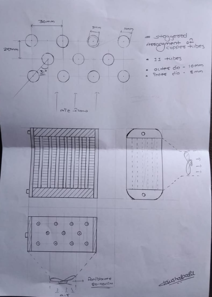
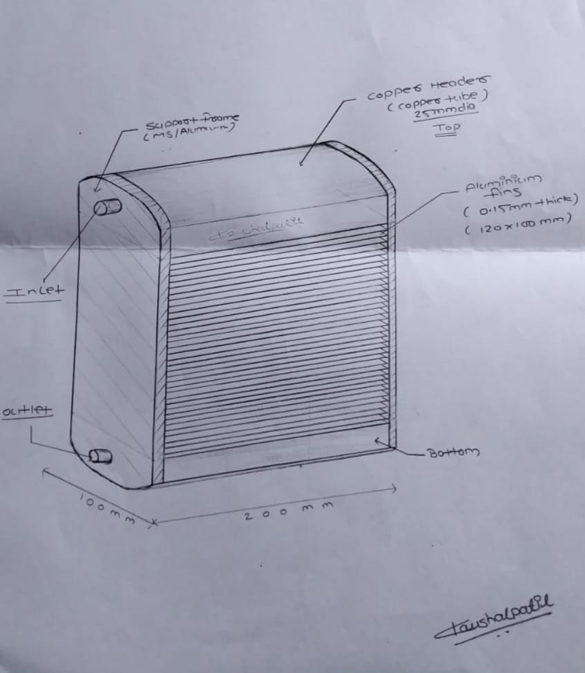
Proposed Parameters for the 1 kW Radiator Prototype
| Parameter | Value |
|---|---|
| Heat Transfer Capacity | 1 kW |
| Hot Water Inlet Temperature | 80–90°C |
| Hot Water Outlet Temperature | 65–70°C |
| Air Inlet Temperature | Ambient |
| Target Air Outlet Temperature | 55–65°C |
| Tube Material | Copper |
| Tube Inner Diameter | 8mm |
| Tube Outer Diameter | 10 mm |
| Tube Length | 200 mm |
| Tube Arrangement | Staggered |
| Fin Material | Aluminium |
| Fin Thickness | 0.16 mm |
| Fin Spacing | 4 mm |
| Number of Fins | 50 |
| Horizontal Tube Pitch | 25 mm |
| Vertical Tube Pitch | 30 mm |
| Water Flow Rate | To be validated experimentally |
| Air Flow Rate | To be validated experimentally |
These parameters were selected as an initial design basis and may be refined after fabrication and experimental testing of the prototype.
JULY FIRST AND SECOND WEEK
Material Procurement and Fabrication Progress
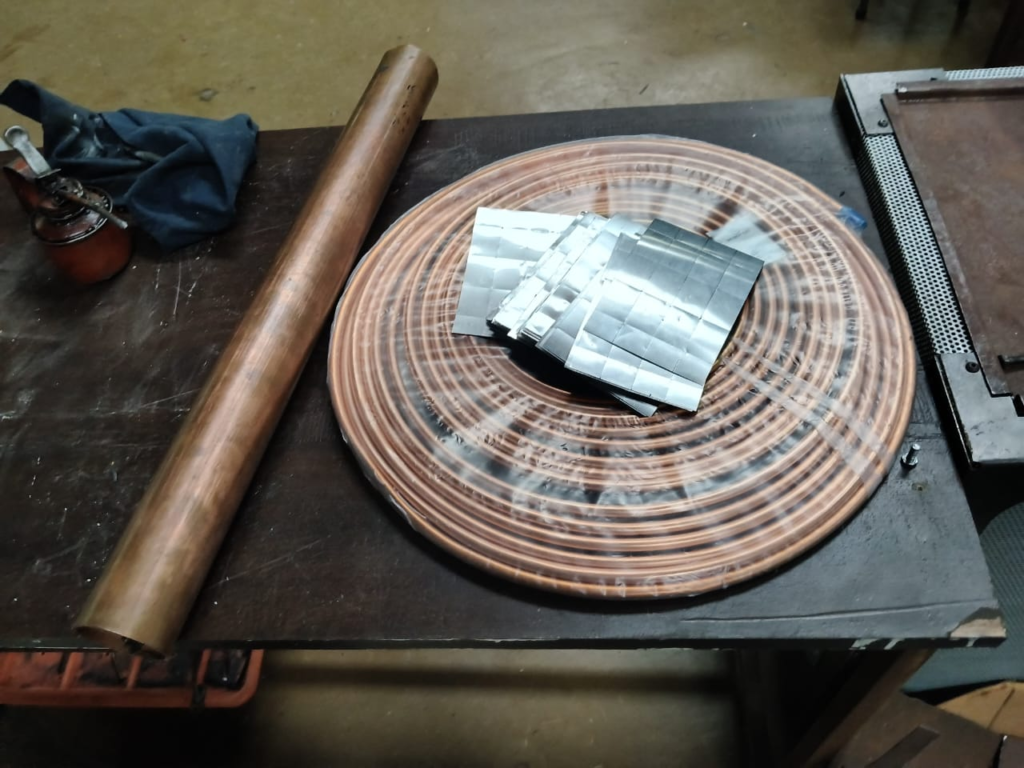
After finalizing the design parameters for the 1 kW radiator prototype, the required materials were identified and procured. The purchased materials included copper tubes, aluminium fin sheets (0.30 mm thickness), and other components required for fabrication.
Following material procurement, the fabrication of the radiator prototype was initiated. The first stage of fabrication involved preparing the aluminium fins according to the finalized dimensions. The fin cutting process was completed, followed by drilling the required holes for the copper tubes. These operations ensured proper alignment of the tubes and laid the foundation for assembling the finned-tube radiator.
With the fin cutting and drilling completed, the project is now ready for the next fabrication stages, including tube assembly, manifold fabrication, brazing, and final radiator assembly.
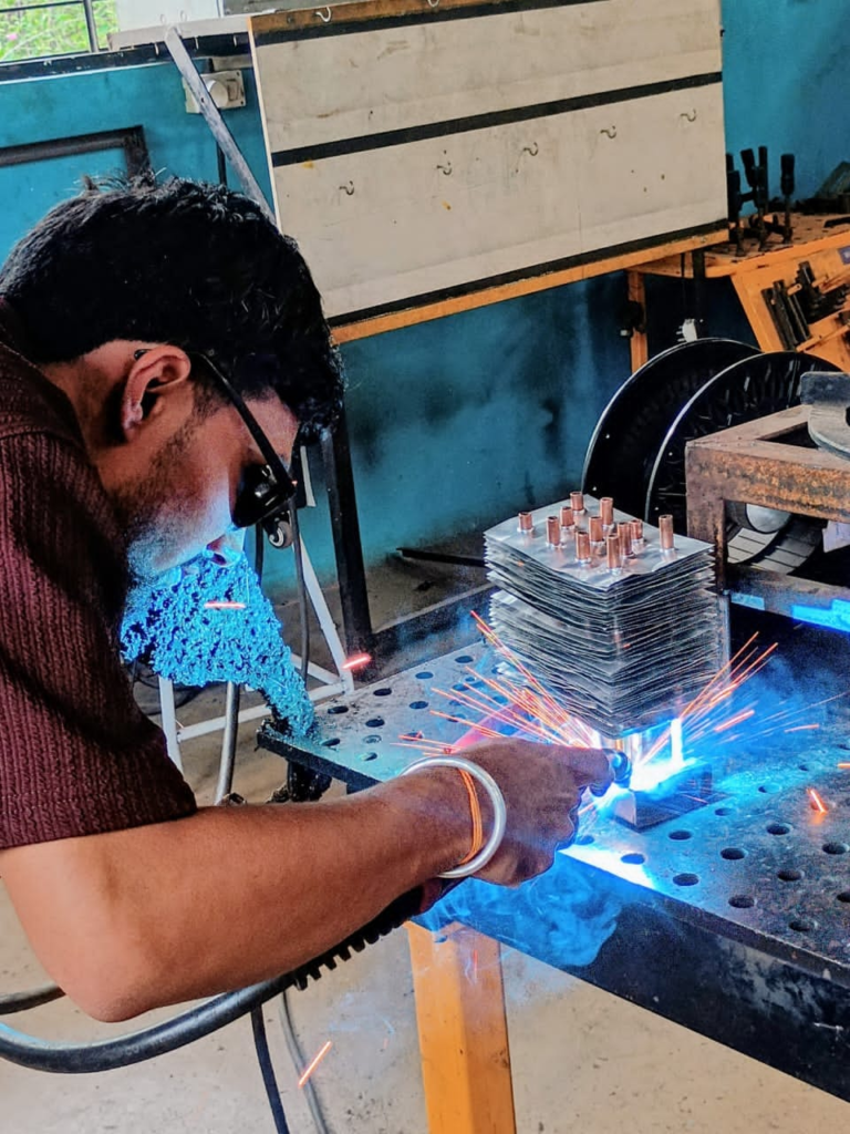
Radiator Assembly, Leakage Testing, and Thermal Testing
After completing the fabrication of the radiator prototype, the copper tubes were assembled with the aluminium fins, and all tube-to-header joints were sealed to ensure a leak-proof system. Proper sealing of these joints is essential to prevent water leakage during operation and to maintain the required pressure within the radiator.
Leakage Test
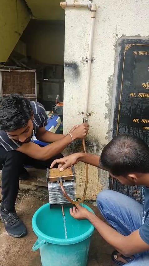
A leakage test was carried out before conducting any thermal performance tests. The radiator was filled with water, and all joints were carefully inspected for leaks.
During the initial test, a small leakage was observed at one of the tube joints. The defective joint was repaired by resealing the connection, and the radiator was tested again. After the repair, no further leakage was observed, confirming that the radiator was ready for thermal testing.
Thermal Testing Procedure
Once the radiator successfully passed the leakage test, thermal testing was initiated to evaluate its heat transfer performance. The following procedure was adopted:
- Connect the radiator to the hot water circulation system.
- Fill the system with water and remove any trapped air from the tubes.
- Start the water circulation .
- Heat the water to the desired inlet temperature (approximately 80–90°C).
- Start the blower to force ambient air through the finned radiator.
- Measure the inlet and outlet temperatures of both water and air at regular intervals.
- Observe the stability of the system and record the temperature rise of the air.
- Analyze the results to evaluate the radiator’s heat transfer performance and identify any scope for further improvement.
Thermal Performance Evaluation
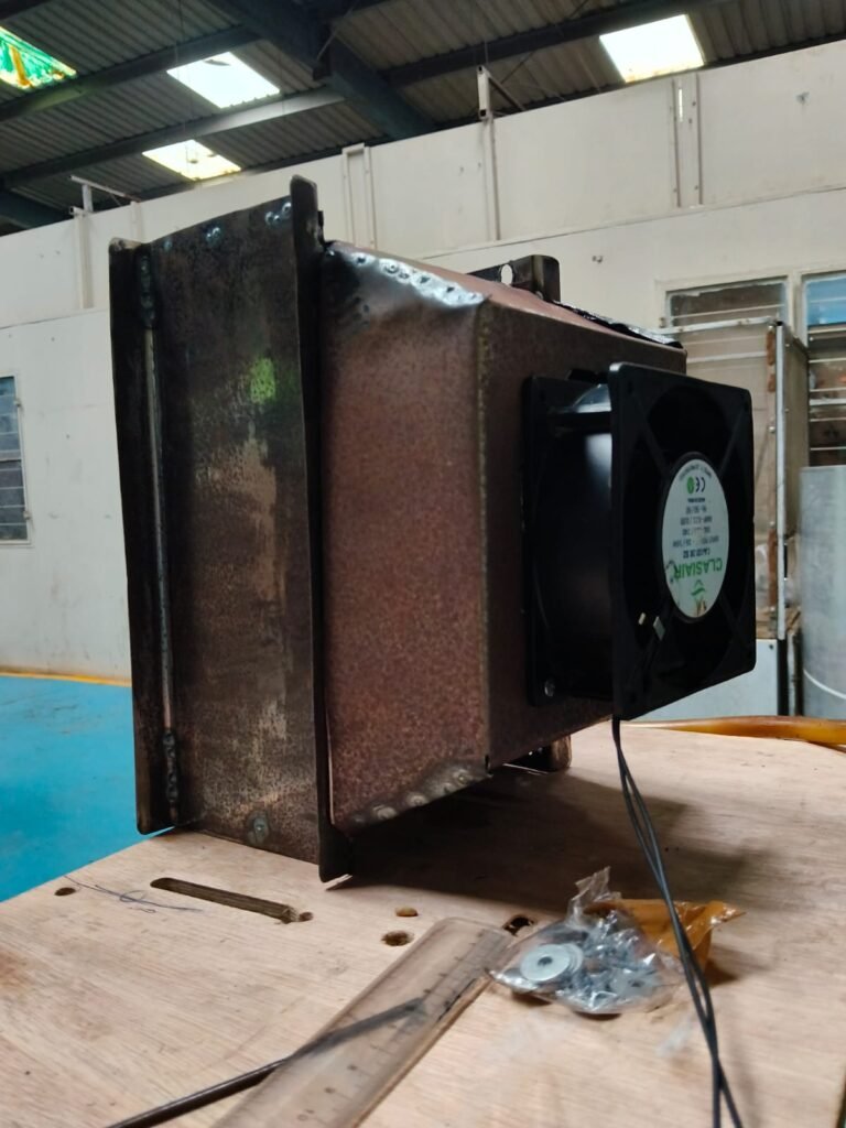
After successfully completing the leakage test, the fabricated 1 kW radiator prototype was subjected to preliminary thermal performance testing. Hot water was circulated through the radiator at a flow rate of 1 L/min, while a 90 CFM blower supplied ambient air across the finned surface. The inlet and outlet temperatures of both water and air were recorded after the system reached steady-state operation.
Experimental Observations
Parameter | Test 1 | Test 2
Water Inlet Temperature (°C) | 85 | 90
Water Outlet Temperature (°C) | 70 | 73
Air Inlet Temperature (°C) | 25 | 25
Air Outlet Temperature (°C) | 34.8 | 35
Water Flow Rate | 1 L/min | 1 L/min
Blower Capacity | 90 CFM | 90 CFM
Heat Transfer Results
Parameter | Test 1 | Test 2
Heat Transfer from Water | 1048 W | 1187 W
Heat Gained by Air | 495 W | 505 W
Discussion
The water-side calculations show that the radiator transferred approximately 1.05–1.19 kW of thermal energy, which is slightly higher than its nominal design capacity of 1 kW. This confirms that the fabricated radiator is capable of delivering the intended heat output under the given operating conditions.
The air-side calculations indicate that the airflow absorbed approximately 0.5 kW of heat. The difference between the water-side and air-side heat transfer values is attributed to heat losses from the radiator to the surroundings, experimental uncertainties, and the fact that the measured air temperature represents a local value rather than the average temperature across the entire outlet section.
Overall, the thermal test successfully demonstrated the operation of the fabricated radiator. The prototype achieved its design objective and validated the heat exchanger concept. Future work will focus on reducing heat losses, improving insulation, optimizing airflow and water flow rates, and increasing the outlet air temperature to meet the requirements of drying applications.