Introduction:-
As the advancement in science & technology is developing, the human comfort & needs are also increasing
proportionally. As all the branches of engineering are working on fulfilling these needs and among all those the
“MECHANICAL & ELECTRONICS” are one of the most important branches to respond to these needs. This Project entitled “Smart Rain Protection Cloth Stand” is small step towards the comfort ability and saving our time. We at Vigyan Ashram try to provide solution on common people problems. Though this project is low cost, easy to understand & simple in construction, this project helps for next generation.
Problem Statement:-
Now a days it’s difficult to predict the changes in season especially during rainy season. In rainy season it’s very rare that we can find sun rays to dry our clothes but how it possible to make our clothes to expose to sun rays as soon as it available. So there is need for human intervention who continuously monitors this but when no is at home during the daytime especially working class peoples, its difficult and many time the dry clothes get wet by rain. So here arise a need to develop a technology to protect the cloths from sudden and unpredicted raining.
There are some existing products in market, but they are not fully automatic, human intervention is required to manually press the switch to operate the system. We also analyzed that the system needs to be hanged on the balcony roof, but what if the house is not having a balcony or a balcony where enough sunlight is not available. Also in Rural Parts most of the households are not having electric dryer, so in their case the cloths have more wetness.
Solution:-
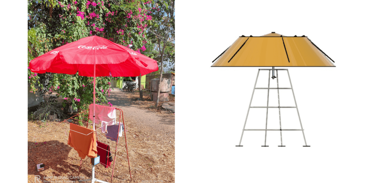
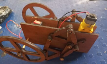
We have designed a automatic system which detect the rain drops and send a signal to microcontroller to open a umbrella mechanism which open a canopy that protects the cloth from rain. in this projects we have used a rain sensor, a Microcontroller, 12 v Geared Dc motor, Waterproof umbrella, Counter Pulley mechanism to open and close the umbrella.
We have used embedded programing which manages the operation and commanding of mechanism. In this system when the first droplet of the rain strikes the rain drop sensor on the top of the umbrella its sends a 3.3v analog output to the bug converter which converts it to 5 v digital output, this output from bug converter is sent to microcontroller which sends signal to Dc motor which rotates clockwise and windup the string that is connected to the umbrella slider, and when the limit switch at top is pressed it stop rotating, similarly when there is not rain the umbrella will close down.
Hardware used:-
- an umbrella that we will improve
- an Arduino board to control the system
- a motor for actuating the opening and closing
- a rain sensor
- two (runner end-of-travel) detection switches: one at the top and one at the bottom of the shaft
- connecting wires
- a 3D printer for machined parts.
General operation of the system:-
When rain is detected at the top of the umbrella via the rain sensor, the motor is activated and the umbrella opens. When the runner* reaches its end of travel, the motor is stopped. The end of the race is detected by one of the detection switches located at the top of the umbrella shaft. In the same principle, the umbrella closes when there is no more rain detected.
*the runner is the sliding element as can be seen in the picture below

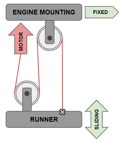
Above is a simplified diagram of the operation of the pulley system associated with the engine. The motor is responsible for providing the torque needed to pull the runner. The two pulleys make it possible to increase the torque and require in return to increase the length of rope to be pulled. The rope is therefore fixed to the mobile part (the runner) which slides around the shaft of the umbrella and to the motor, itself fixed to the “ENGINE MOUNTING” which does not move.
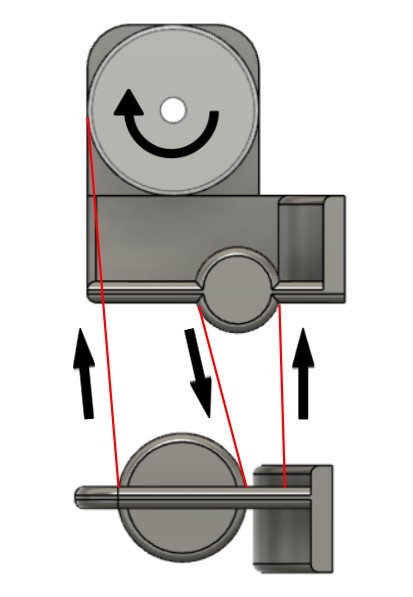
The two pulleys visible on the simplified diagram are virtual: in truth there is enough little friction for the rope to turn around these fixed cylinders. It is therefore important not to confuse the two so-called virtual pulleys which increase the torque of the engine and the engine pulley which serves as the moving cylinder where the rope is wound. The latter is therefore the only part that can turn on itself.

The motor mount is attached to the very top of the umbrella shaft, just below the finial and protected from the rain.
Presentation of the electronic circuit
In order to control the motor we are using the L298n dual H-bridge motor driver controller module and an Arduino UNO board for the algorithm.
On the following link you can find explanations on what is a motor driver and how it works: Robocraze link.
On the following link you can find a tutorial on how to use the L298N Motor Driver with DC motors: Create Arduino Link.
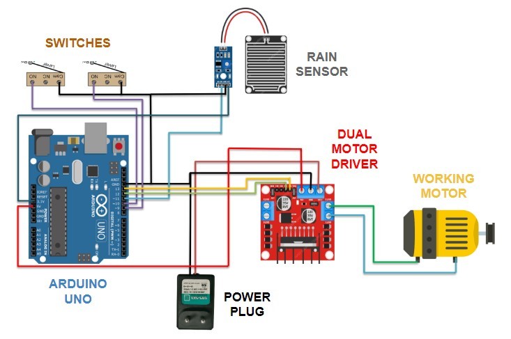
Above you can see the electronic circuit diagram made by Sumit Thakare. Its general operation is simple:
- The general power supply is via the connected power plug, which is connected to the L298N board.
- The L298N dual motor driver provides motor control and powers the Arduino board.
- The Arduino code is saved in the Arduino UNO board and it is explained in the following part “Presentation of the Arduino code”, it is the algorithm that links the sensors (rain and switches) with the motor.
- The motor is almost always stopped, indeed the pulley system keeps the runner in the right place without the engine providing torque. The engine is therefore activated only to open and close the umbrella.
Presentation of the Arduino code:-
Arduino is an open-source hardware and software company. In this project we use a single board microcontroller called Arduino UNO. Documentation on its operation is easily found on the internet. In the following paragraphs we will quickly review the 3 parts of the Arduino program and roughly explain how it works.
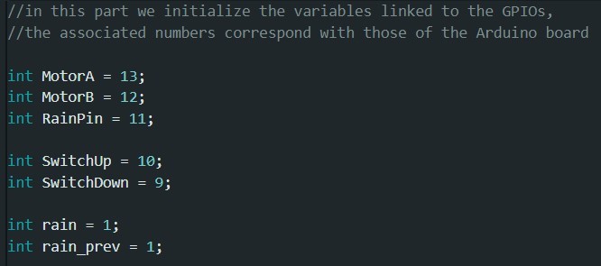
Screenshot of the first part of the Arduino code
A variable is a place to store a piece of data. It has a name, a value, and a type. The type used is int, integers are the primary data type for storing numbers. Here, we use it to indicate the ports used and initialize the variables associated with the rain detection.
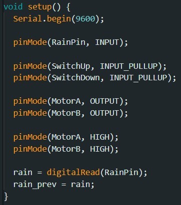
Screenshot of the second part of the Arduino code
The void setup() is the first function to be executed in the sketch and it is executed only once. Three things can be noticed here:
- Serial.begin is used to establish serial communication between our computer screen and the Arduino board. We only used this communication for testing purposes, it does not bring any necessity to the operation of the program.
- The pin modes we initialized in the first part of the code are set on the Arduino to either OUTPUT or INPUT. For a sensor it is an input, for a motor an output. INPUT_PULLUP is used for switches and enable the internal pull-up resistor. The motor is configured at standstill.
- The digitalRead function reads the value from a specified digital pin, either HIGH or LOW. Here we use it to know if rain is detected when we turn on or reset our system.
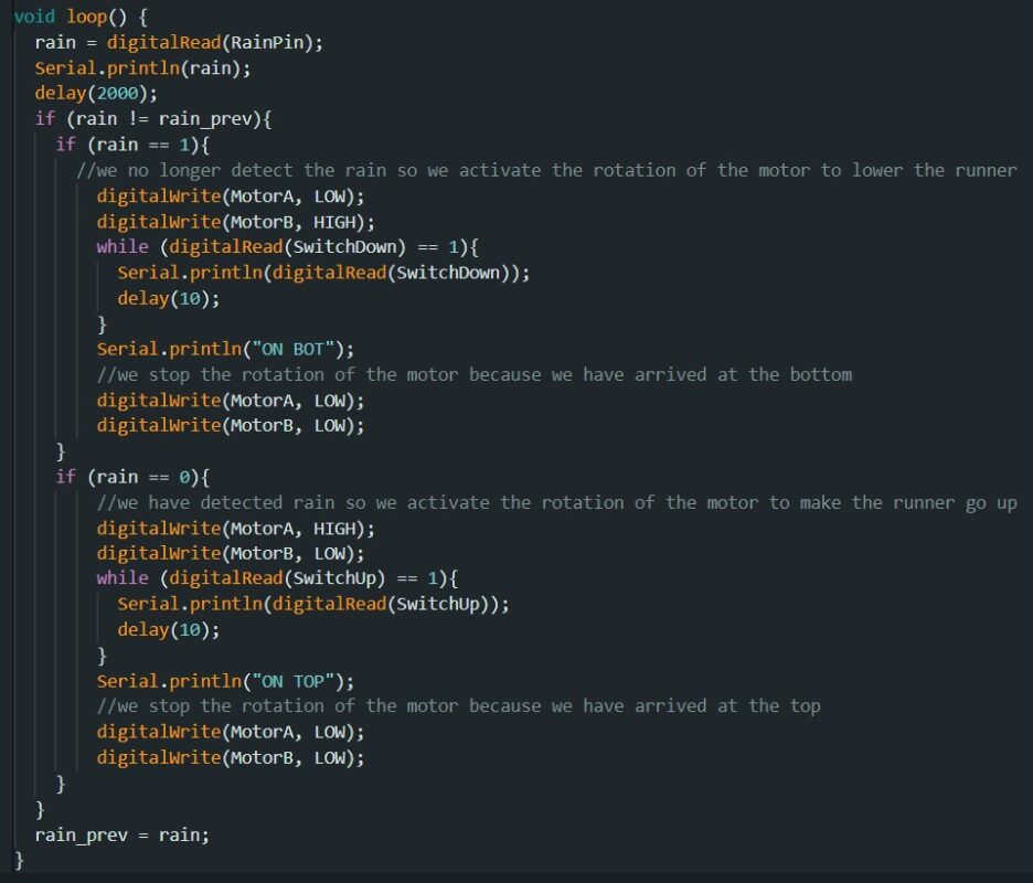
Screenshot of the third part of the Arduino code
Third part explanations.
Presentation of the computer-aided design part:-
Explanations on the laser cutter.
Explanations on the box housing the electronic circuit and the Arduino UNO card.
Creating a DXF file to make a box is made easy by the Makercase website. You will find the link to get there here.
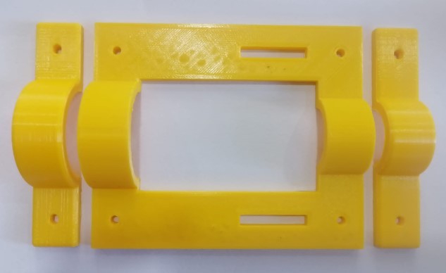
The part that holds the Arduino box to the umbrella shaft after it was 3D printed with the Fraktal Works machine
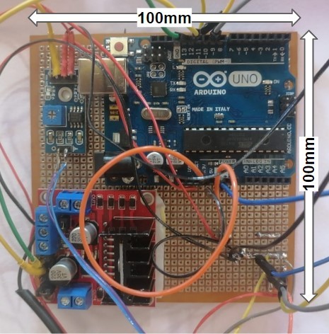
Photo of the arduino electronic assembly to be encapsulated

