
Introduction
When drying laundry outdoors, it is impractical to have to run to protect the laundry from the rain when it starts, especially when no one is there. It rains on average 68 days a year in Pune according to the following site: https://www.currentresults.com/Weather/India/average-yearly-precipitation.php. The idea proposed by Vigyan Ashram is therefore to automate a system that opens an umbrella above the clothesline when raindrops are detected, in order to make life easier for people.
On the photo above you can see the 3 collaborators of the project taking tea under the functional umbrella. From left to right: Basile Pasquale, Sumit Thakare and Pierre-Jean Martin. Click on their name to access their blog!
In this blog we will first see the general principle of our solution, then we will successively present the electronic parts, Arduino code and computer-aided design.
Hardware used
- an umbrella that we will improve
- an Arduino board to control the system
- a motor for actuating the opening and closing
- a rain sensor
- two (runner end-of-travel) detection switches: one at the top and one at the bottom of the shaft
- connecting wires
- a 3D printer for machined parts
- a laser cutter for the shelter box
Software used
- Arduino IDE for the coding part
- RDWorks V8 for the DXF design
- Autodesk Fusion 360 for the 3D design
- Fracktory to convert to 3D-printable files
General operation of the system
When rain is detected at the top of the umbrella via the rain sensor, the motor is activated and the umbrella opens. When the runner* reaches its end of travel, the motor is stopped. The end of the race is detected by one of the detection switches located at the top of the umbrella shaft. In the same principle, the umbrella closes when there is no more rain detected.
*the runner is the sliding element as can be seen in the picture below.

It was decided to use a system of pulleys rather than gears to increase the torque of the motor. This system has the advantage of being more adaptable to all engines. In addition, we ensure that the opening of the umbrella is maintained even in the event of a power cut because the motor must not provide any torque to keep the umbrella closed or open.
The working principle of a pulley is simple: it helps to reverse the direction of lifting force. When one end of the rope is pulled downwards, the load on the other end of the rope is pulled upward. But that’s not all! With multiple pulleys, you reduce the forces used to lift the same load. For example, with two pulleys, the load lifted is theoretically reduced by two and the length of rope pulled is multiplied by two. In our case, the rope wraps little by little around the axis of the motor.
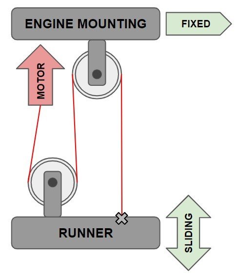
Above is a simplified diagram of the operation of the pulley system associated with the engine. The motor is responsible for providing the torque needed to pull the runner. The two pulleys make it possible to increase the torque and require in return to increase the length of rope to be pulled. The rope is therefore fixed to the mobile part (the runner) which slides around the shaft of the umbrella and to the motor, itself fixed to the “ENGINE MOUNTING” which does not move.
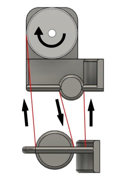
The two pulleys visible on the simplified diagram are virtual: in truth there is enough little friction for the rope to turn around these fixed cylinders. It is therefore important not to confuse the two so-called virtual pulleys which increase the torque of the engine and the engine pulley which serves as the moving cylinder where the rope is wound. The latter is therefore the only part that can turn on itself.

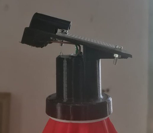
The motor mount is attached to the very top of the umbrella shaft, just below the finial and protected from the rain.
Presentation of the electronic circuit
In order to control the motor we are using the L298n dual H-bridge motor driver controller module and an Arduino UNO board for the algorithm.
On the following link you can find explanations on what is a motor driver and how it works: Robocraze.
On the following link you can find a tutorial on how to use the L298N Motor Driver with DC motors: Create Arduino.

Above you can see the electronic circuit diagram made by Sumit Thakare. Its general operation is simple:
- The general power supply is via the connected power plug, which is connected to the L298N board.
- The L298N dual motor driver provides motor control and powers the Arduino board.
- The Arduino code is saved in the Arduino UNO board and it is explained in the following part “Presentation of the Arduino code”, it is the algorithm that links the sensors (rain and switches) with the motor.
- The motor is almost always stopped, indeed the pulley system keeps the runner in the right place without the engine providing torque. The engine is therefore activated only to open and close the umbrella.
Presentation of the Arduino code
Arduino is an open-source hardware and software company. In this project we use a single board microcontroller called Arduino UNO. Documentation on its operation is easily found on the internet. In the following paragraphs we will quickly review the 3 parts of the Arduino program and roughly explain how it works.

A variable is a place to store a piece of data. It has a name, a value, and a type. The type used here is int, integers are the primary data type for storing numbers. We use it to indicate the ports used and initialize the variables associated with the rain detection.

The void setup() is the first function to be executed in the sketch and it is executed only once. Three things can be noticed here:
- Serial.begin is used to establish serial communication between our computer screen and the Arduino board. We only used this communication for testing purposes, it does not bring any necessity to the operation of the program.
- The pin modes we initialized in the first part of the code are set on the Arduino to either OUTPUT or INPUT. For a sensor it is an input, for a motor an output. INPUT_PULLUP is used for switches and enable the internal pull-up resistor. The motor is configured at standstill.
- The digitalRead function reads the value from a specified digital pin, either
HIGHorLOW. Here we use it to know if rain is detected when we turn on or reset our system.

The void loop() function is where most of the Arduino sketching is done. The program starts directly after the opening bracket ( { ), runs until it sees the closing bracket ( } ), goes back to the first line of loop() and starts over. First, we check if rain is detected. If rain is detected and as long as it is the umbrella must be in the open position. As soon as rain is no longer detected and as long as there is none, the umbrella must be in the closed position.
Presentation of the computer-aided design part
For safety and aesthetic reasons, it is important to protect the electronic components surrounding the Arduino board. We therefore decided to create a shelter box from parts cut using the Fab Lab’s laser cutter.

Laser cutting is a method of cutting shapes or designs from sheet metal or other structural materials used in many fields. To tell the machine how the part should be cut, we use the RDWorks V8 software and we design a suitable DXF file there. Creating a DXF file to make a box is made easy by the Makercase website. You will find the link to get there here.

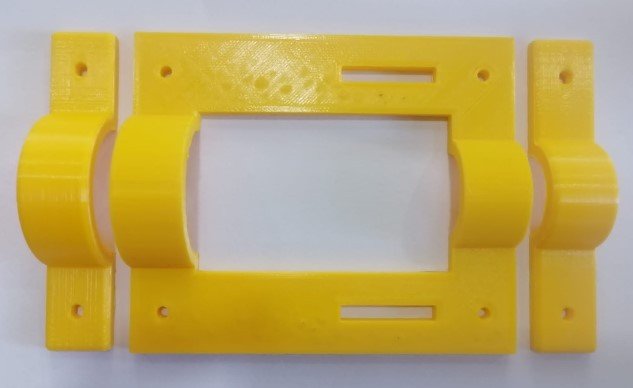
We used the Fab Lab 3D printer to make the parts attached to the umbrella shaft. It’s a Fraktal Works Julia. The parts were designed on the Autodesk Fusion 360 software then the files were then converted using the Fracktory software to be printed.


It was a real pleasure to work on this project with my friends Basile and Sumit! 🙂