Introduction-
School spends lot of money on purchasing instruments such as measuring devices and because of poor knowledge they are not used properly .So I decided took a Smart Phone as Lab project. In that project sensor value is displayed on smart phone through Bluetooth. As smart phone is user friendly. Today smart phone is available at any person.
Objective-
Multiple sensor check on one device.
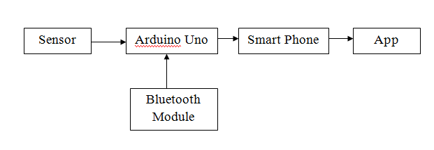
Block Diagram-
Material-
- Arduino uno
- Sensors
- Smart Phone
- App
- Jumper wires
- Usb cable(For Arduino )
- Bluetooth Module(HC-05)
Description-
I have survey on a project. Main task of a project is how to send sensor data to smart phone. I was searched two methods one is Bluetooth and another one is WiFi. WiFi range is not available everywhere & it is very costly. Everytime internet is required. So I decided go through a Bluetooth. It is available in phone, so no cost paid for it. It is very chip &uses every person.
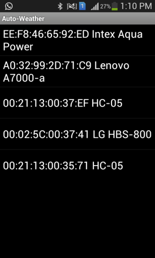
Bluetooth Connection –
I have used HC-05 bluetooth module. First of all establish connection in phone Bluetooth and this Bluetooth module.
Step1 – Bluetooth module connected to arduino.
Step2- Turn on phone’s Bluetooth.
Step3 – scan for Bluetooth device (HC-05).
Step4- Enter pin 1234 for pairing device.
Note for Bluetooth –
- Bluetooth module connected to 3.3V only.
- Tx pin of Bluetooth module connected to arduino Rx.
- Rx pin of Bluetooth module connected to arduino Tx.
- Bluetooth is disconnected at the time of program uploading to arduino.
App Information –
I have Arduino app download from google play store. It is for temperature & humidity app. I tried this app. A temperature and humidity data display on an app.

Connection

Sensor Data Display on App
Another task is making app. MIT app inventor is free software for create your own App. I was tried one button create on MIT app inventor software & app is displayed on my smart phone. Communication between controller and smart phone refer following link.

MIT app inventor

Display on Smart Phone
I have successfully made my app. This made in MIT app inventor 2 software. My app name is Temperature. Check DHT11 sensor data on app.

DHT11 + Bluetooth + Arduino

Sensor data on my App
After that I have purchased some Air pollution Detector Sensor like
- MQ6 — It detects LPG Gas leakage.
- MQ7— It detects Carbon Monoxide (CO) Gas.
- MQ135—- It detects CO2, Smoke, Alcohol, and NH3.
- LDR ——- it detects intensity of light.
- DHT 22—- It detects Temperature and Humidity.
I am tiring to do a gas sensor value converted into PPM units. But calibration of sensor is required for PPM conversion. So firstly I shows analog value of multiple sensor is displayed on App. I have referred instructable link for a readymade app. required for PPM conversion. So firstly I shows analog value of multiple sensor is displayed on App. I have referred instructable link for a readymade app. This app name is Ardutooth. I have showed multiple sensor data on app.

Multiple Sensor data on readymade app
I was getting readings of sensors in readymade app. Then I decided make an own app for multiple sensor data display. I have design my app UI. In which I am creating two screens for Bluetooth connection enable on first screen and data receive on second screen. But it gives error Bad arguments.

Screen 1

Screen 2
I do not understand this error. So I wrote a post on MIT app inventor 2 Forum. He was told me Bluetooth connection is not enable on two screens. Bluetooth connection was enabling on only one screen. It receives data on same screen not on different screen. If data receives on second screen then this screen replace by virtual screen. After that I was decided sensor data receive on same screen. I have made new UI for that.

Hardware Setup-
Material list-
- Arduino Uno
- Temperature Sensor (DHT22)
- LDR (Light Dependent Resistor) module
- LPG Gas Sensor module (MQ6)
- Carbon Monoxide Gas Sensor module (MQ7)
- Carbon Dioxide Gas Sensor module (MQ135)
- Bluettoth Module (HC-05)
- USB Cable
- Jumper Wires (Male To Female)
Temperature sensor –

DHT22
DHT22 output calibrated digital signal. It utilizes exclusive digital-signal-collecting-technique and humidity sensing technology. This senor has more accurate than DHT11 sensor. That’s why I choose this sensor.

Code

Hardware

Output
LPG Gas Sensor –
MQ6 Gas Sensor is used as LPG,Butane and Propen Sensing gas.It is highly sensitive gas sensor to petroleum based but less sensitive to Alcohol and Carbon dioxide. This simple sensor can be installed in the kitchen to give warning alarm if there is leakage. It is 4 pin modules and it requires 5 volt DC.

MQ6 Gas Sensor
Calibration is required for each gas sensor. I was calibrating MQ6 gas sensor at basic level. Calibration is done in kitchen. Before calibration sensor got values from 150 to 500 and after calibration sensor got values from 500 to 750.

Test code MQ6 (LPG) sensor

Calibration of LPG sensor
Carbon Dioxide Gas Sensor –
The MQ135 gas sensor has high sensitivity in ammonia, sulfide, benzene steam, smoke, carbon dioxide and in other harm full gas. The operating voltage of this gas sensor is from 2.5V to 5.0V. The MQ-135 gas sensor is low cost to purchase. The gas sensor layer of DC.the sensor unit is made up of tin dioxide (SnO2). It is 4 pin modules and it requires 5 volt DC.

MQ135 Gas Sensor
I was calibrating MQ135 gas sensor at basic level. More amount of carbon dioxide is not available in air, so I was making carbon dioxide gas using vinegar and baking soda. Then get readings from a sensor. Made CO2 gas using vinegar and soda used below link. Before calibration sensor got values from 250 to 400 and after calibration sensor got values from 400 to 600.

CO2 (MQ135) Test code

Calibration of CO2 sensor
Carbon Monoxide Gas Sensor –
This is a simple-to-use Carbon Monoxide sensor, suitable for sensing CO concentrations in the air. This sensor has a high sensitivity and fast response time. The sensor’s output is an analog resistance. It is 4 pin modules and it requires 5 volt DC.

CO (MQ7) Gas Sensor
I was calibrating MQ7 gas sensor at basic level. Carbon monoxide generate from laser cut exhaust and silencer of bike or car. I was calibrating CO sensor at laser cut exhaust. Before calibration sensor got values from 100 to 350 and after calibration sensor got values from 350 to 550.

CO (MQ7) Test code
LDR Sensor –
The light sensor for a lux meter can be one of several different types of sensors, including photodiodes and phototransistors, but the easiest to use and often the most readily available type of sensor is a photoresistor or light dependent resistor (LDR). The resistance of an LDR changes as the amount of light falling on it changes. The brighter a light lower the resistance.
A luxmeter is a device that measures illuminance and luminous emittance using the SI unit of lux. It effectively measures the amount of power from the light falling on a given unit of area, except that the power measurement is weighted to reflect the sensitivity of the human eye to varying wavelengths of light. A simpler way to describe a lux meter is to say that it measures how bright the light falling on the sensor is. I was referred below link for calibrating LDR Sensor.
https://www.allaboutcircuits.com/projects/design-a-luxmeter-using-a-light-dependent-resistor/
Calibration of LDR Sensor Steps-
- Connect the DMM to the two leads of the LDR module and set it to measure resistance.
- Place the sensor of the commercial light meter (luxmeter) beside the LDR.
- The same levels of light fall on the two sensors.
- Take a reading of the LDR resistance and the light meter lux. Repeat this process for many different lighting levels from very dark (near 0 lux) to very bright (thousands of lux).

Calibration of LDR Module

LDR test code

Output
Bluetooth Module (HC-05) –
HC-05 module is an easy to use Bluetooth SPP (Serial Port Protocol) module, designed for transparent wireless serial connection setup. Bluetooth is a wireless technology standard for exchanging data over short distances (using short-wavelength UHF radio waves in the ISM band from 2.4 to 2.485 GHz). It is low cost module than wifi.

Bluetooth (HC-05) Module
I have used HC-05 bluetooth module. First of all establish connection in phone Bluetooth and this Bluetooth module.
Step1 – Bluetooth module connected to arduino.
Step2- Turn on phone’s Bluetooth.
Step3 – scan for Bluetooth device (HC-05).
Step4- Enter pin 1234 for pairing device.
Note for Bluetooth –
- Bluetooth module connected to 3.3V only.
- Tx pin of Bluetooth module connected to arduino Rx.
- Rx pin of Bluetooth module connected to arduino Tx.
- Bluetooth is disconnected at the time of program uploading to arduino.
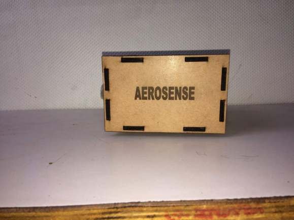
Assembly –
I was designed a box in solid works software and cut into laser cutting machine.

Laser cut plates

All sensors connected to arduino

Final Box


Final output on App –
Step 1 – Touch on fablab logo.
Step 2 – Then select Bluetooth module
Step 3 – Seen sensor data on app.


