Introduction
In Week 4 – Output Devices of Fab Academy, we learned about different types of output devices and how they are used to display information or produce actions from a microcontroller. We understood how output devices such as LEDs, buzzers, LCD displays, and other output components work by receiving signals from a microcontroller. During this week, we connected and programmed different output devices using Arduino and ESP32 boards. We wrote simple programs to control these devices, such as blinking LEDs, displaying text on an LCD, and activating a buzzer. This hands-on practice helped us understand how microcontrollers communicate with output devices and how they are used in embedded systems and real-world electronic projects.
Group Assigment
Measure the power consumption of an output device.
Measured the power consumption of an output device (Yellow BO Motor)??
A yellow BO motor, also called a Battery Operated motor or yellow DC geared motor, is a small electric motor that has a built-in gearbox. It is one of the most commonly used motors in robotics, electronics, and school or college projects. The small DC motor inside rotates at a very high speed, while the gearbox reduces the speed and increases the torque (turning force). This allows the motor to move wheels and carry small loads more easily. Most yellow BO motors work with a power supply of about 3V to 6V, although some versions support higher voltages.
The yellow BO motor is lightweight, inexpensive, and easy to connect with microcontrollers such as the ESP32, Arduino, and Raspberry Pi using a motor driver. It is mainly used in robot cars, line-following robots, obstacle-avoiding robots, smart vehicles, and other DIY electronic projects. The motor usually has a yellow plastic body with a D-shaped output shaft, making it easy to attach wheels directly. Its simple design and reliable performance make it a popular choice for beginners who are learning robotics and embedded systems.
One of the biggest advantages of the yellow BO motor is that it provides good torque while consuming relatively low power. The built-in plastic gears help the motor rotate smoothly and make it suitable for small robotic applications. However, because the gearbox is made of plastic, it is not designed for very heavy loads or high-impact use. Despite this limitation, the yellow BO motor remains one of the best motors for educational projects, prototypes, and small mobile robots because it is affordable, easy to use, and widely available.

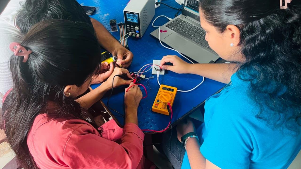
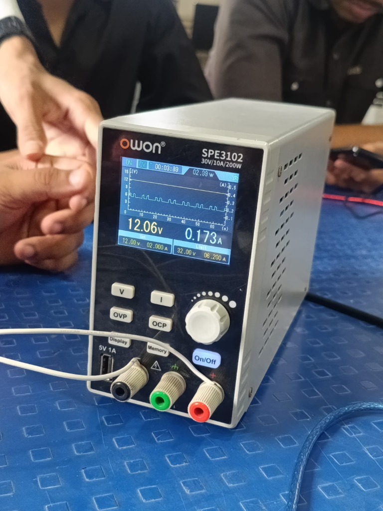
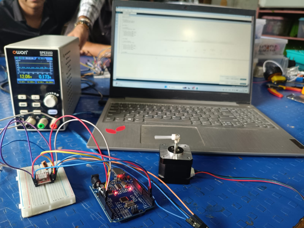
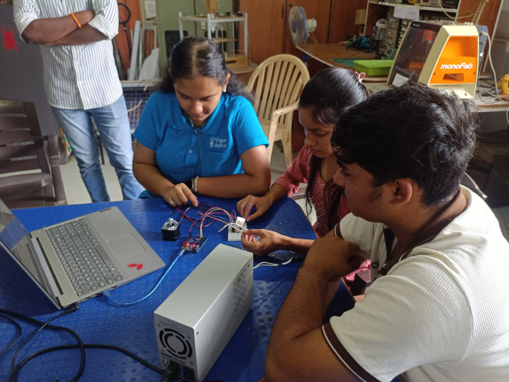
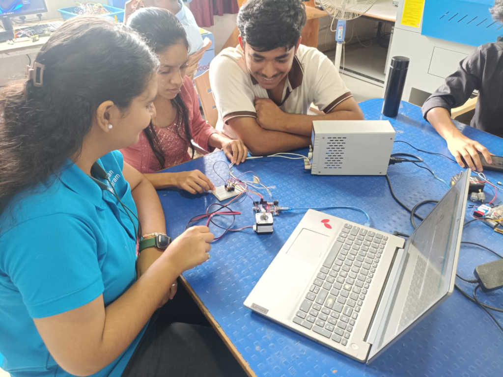
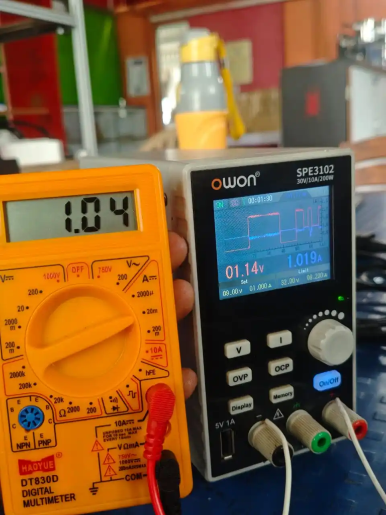
As a part of our group assignment, we connected a yellow BO motor with an Arduino Uno. First, we uploaded the program to the Arduino Uno and connected the motor to the circuit. We also attached a wheel to the shaft of the yellow BO motor. To run the motor, we used a variable power supply so that we could provide the required voltage.
After the motor started running, we measured its voltage and current using a digital multimeter. We observed that the motor was operating at approximately 8.83 volts and was consuming about 1.04 amperes of current. This activity helped us understand how a yellow BO motor works, how it can be connected with an Arduino Uno, and how to measure its electrical parameters using a multimeter.
What is Output Devices
What are Output Devices?
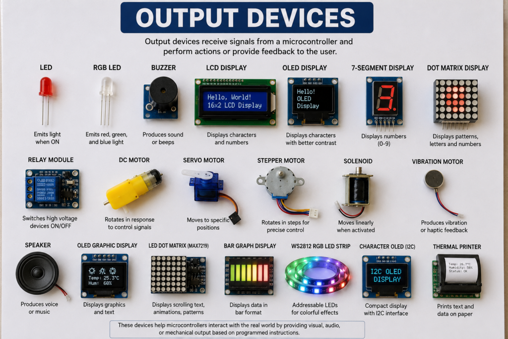
Output devices are electronic components that receive signals from a computer or microcontroller and show the result to the user. They do not send information to the system. Instead, they perform an action such as producing light, sound, or displaying text.
Some common output devices are LEDs, buzzers, LCD displays, motors, and speakers. For example, an LED glows, a buzzer makes a sound, and an LCD shows text or numbers. Output devices are used in many electronic projects to give information or show that the system is working.
Datasheet of Output devices
| Sr. No. | Output Device | Function | Output Type | Operating Voltage | Applications |
|---|---|---|---|---|---|
| 1 | LED (Light Emitting Diode) | Produces visible light when powered | Light | 2–3.3V | Status indicators, lighting, signal indication |
| 2 | RGB LED | Produces red, green, and blue light to create multiple colors | Light | 3.3V–5V | Decorative lighting, displays, status indication |
| 3 | Buzzer | Produces sound or beeps | Sound | 3.3V–5V | Alarm systems, notifications, warning signals |
| 4 | LCD Display (16×2) | Displays text, numbers, and symbols | Visual Display | 5V | Information display, measurement systems |
| 5 | Dot Matrix Display (8×8) | Displays characters, patterns, and animations | Visual Display | 5V | Digital signs, scrolling text, graphics |
| 6 | Relay Module | Switches high-voltage or high-current loads using a low-voltage signal | Electrical Switching | 5V | Home automation, motor control, appliance switching |
| 7 | DC Motor | Converts electrical energy into continuous rotational motion | Mechanical Motion | 3V–12V (depends on motor) | Fans, robots, conveyors, toys |
| 8 | Servo Motor | Rotates to a precise angle (0°–180° or more) | Mechanical Motion | 4.8V–6V | Robotic arms, automation, steering systems |
| 9 | Stepper Motor | Rotates in fixed steps for accurate position control | Mechanical Motion | 5V–12V (depends on motor) | CNC machines, 3D printers, robotics, positioning systems |
Individual Assignment
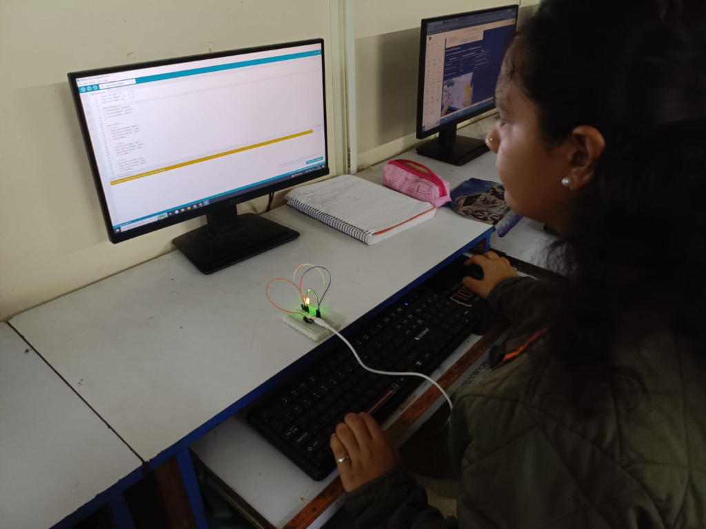
For the individual assignment, I connected different output devices to a microcontroller and programmed them to test their functionality
Components Used
1. LED
A Light Emitting Diode (LED) is a small electronic output device that produces light when electric current passes through it. It is widely used in electronic circuits as an indicator, display light, and lighting source. LEDs use very little power, last for a long time, and turn on instantly, making them more efficient than ordinary bulbs.
Internal Structure of an LED
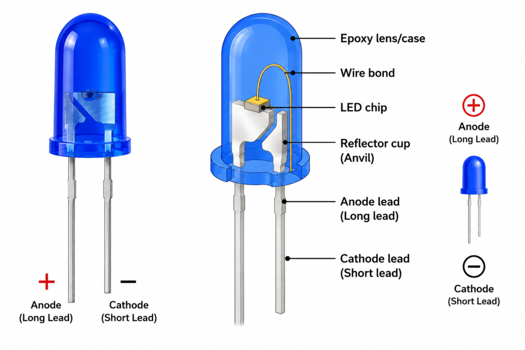
An LED is made of a P-N junction semiconductor chip placed inside a transparent plastic cover called an epoxy lens. It has two terminals: the anode (+) and the cathode (−). When current flows from the anode to the cathode, the semiconductor chip emits light. The plastic cover protects the LED and helps spread the light evenly.
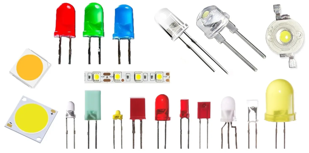
Types Of LED
| Type of LED | No. of Pins | Description | Applications |
|---|---|---|---|
| Single Color LED | 2 Pins | Produces one color such as red, green, blue, yellow, or white. | Indicators, status lights |
| Bi-Color LED | 3 Pins | Contains two LED chips and can produce two colors (e.g., red and green). | Status indicators, signal lights |
| RGB LED (Common Cathode/Common Anode) | 4 Pins | Contains red, green, and blue LEDs in one package. Can produce many colors by mixing RGB. | Decorative lighting, displays, Arduino projects |
| RGB SMD LED | 6 Pins | Surface-mount RGB LED used on PCBs and LED strips. | LED displays, lighting |
| Addressable RGB LED (WS2812B / NeoPixel) | 3 Pins | Has a built-in controller. Each LED can display a different color independently. | LED strips, animations, smart lighting |
| COB (Chip-on-Board) LED | 2 Pins | Contains many LED chips on one board to produce high brightness. | Floodlights, street lights, lamps |
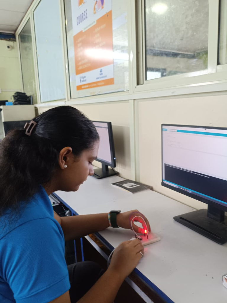
Checking Voltage And Current
Code Used
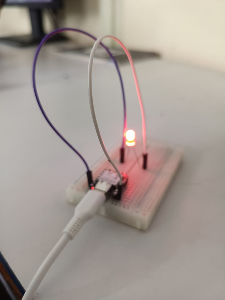
const int LED_PIN = 2;

void setup() {
  pinMode(LED_PIN, OUTPUT);
}

void loop() {
  digitalWrite(LED_PIN, HIGH);  // LED ON
  delay(1000);                  // Wait 1 second

  digitalWrite(LED_PIN, LOW);   // LED OFF
  delay(1000);                  // Wait 1 second
}
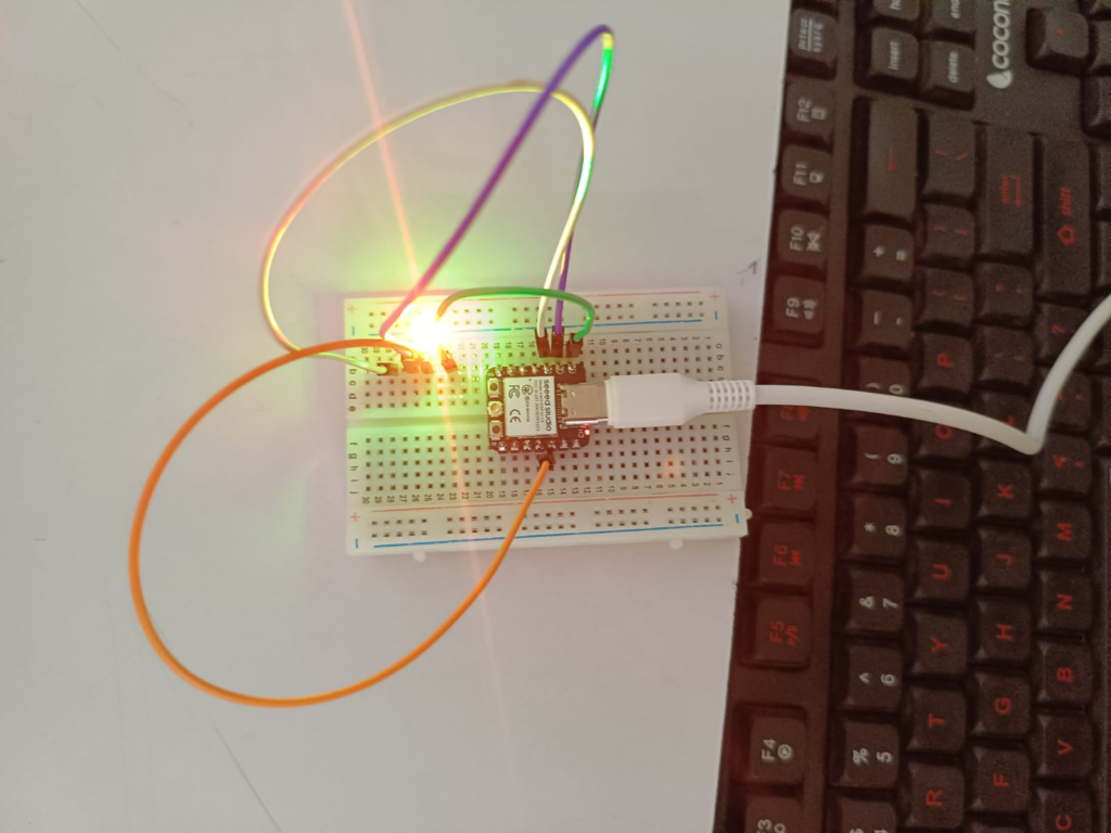
2. RGB LED
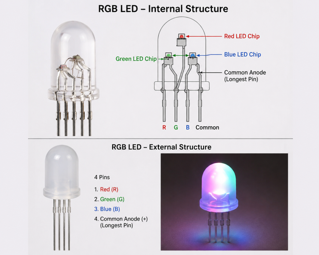
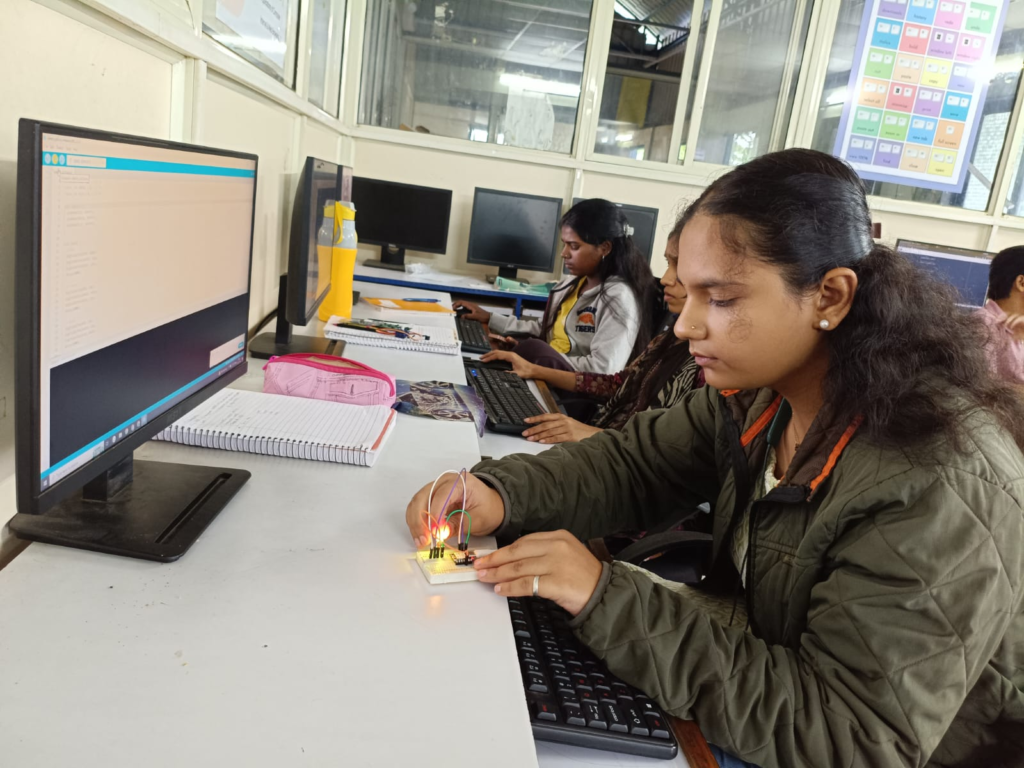
An RGB LED is a special type of LED that can produce many different colors using three small LEDs inside one package. The three colors are Red, Green, and Blue (RGB). By changing the brightness of each color, the RGB LED can create different colors such as yellow, purple, cyan, white, and many more.
RGB LEDs are commonly used in electronic projects, decorative lighting, displays, gaming devices, and smart home products. They make projects more attractive by showing different colors for different conditions, such as indicating power, warnings, or system status. RGB LEDs can be controlled using a microcontroller like Arduino or ESP32 to create colorful lighting effects and animations.
Code Used
const int RED = 2;     // D2
const int GREEN = 3;   // D3
const int BLUE = 4;    // D4

void setup() {
  pinMode(RED, OUTPUT);
  pinMode(GREEN, OUTPUT);
  pinMode(BLUE, OUTPUT);
}

void loop() {
  // Red
  digitalWrite(RED, HIGH);
  digitalWrite(GREEN, LOW);
  digitalWrite(BLUE, LOW);
  delay(1000);

  // Green
  digitalWrite(RED, LOW);
  digitalWrite(GREEN, HIGH);
  digitalWrite(BLUE, LOW);
  delay(1000);

  // Blue
  digitalWrite(RED, LOW);
  digitalWrite(GREEN, LOW);
  digitalWrite(BLUE, HIGH);
  delay(1000);

  // Yellow (Red + Green)
  digitalWrite(RED, HIGH);
  digitalWrite(GREEN, HIGH);
  digitalWrite(BLUE, LOW);
  delay(1000);

  // Cyan (Green + Blue)
  digitalWrite(RED, LOW);
  digitalWrite(GREEN, HIGH);
  digitalWrite(BLUE, HIGH);
  delay(1000);

  // Magenta (Red + Blue)
  digitalWrite(RED, HIGH);
  digitalWrite(GREEN, LOW);
  digitalWrite(BLUE, HIGH);
  delay(1000);

  // White (Red + Green + Blue)
  digitalWrite(RED, HIGH);
  digitalWrite(GREEN, HIGH);
  digitalWrite(BLUE, HIGH);
  delay(1000);

  // Off
  digitalWrite(RED, LOW);
  digitalWrite(GREEN, LOW);
  digitalWrite(BLUE, LOW);
  delay(1000);
}
3.Servo Motor
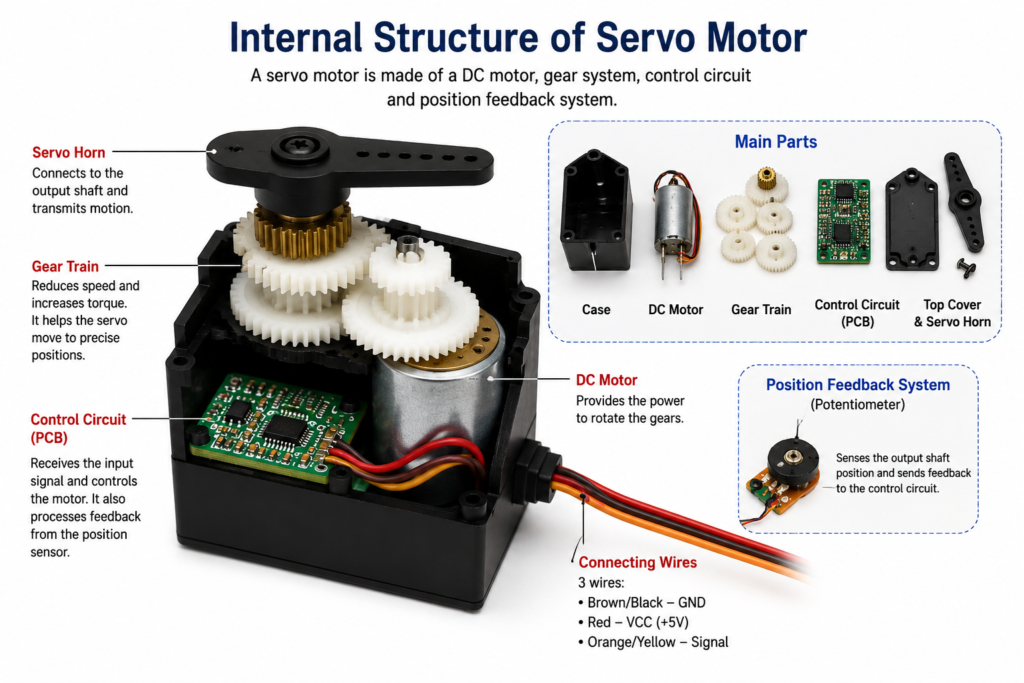
A servo motor is a small electric motor that can move to a fixed position with high accuracy. Unlike a normal DC motor that keeps rotating, a servo motor can rotate to a specific angle such as 0°, 90°, or 180°. It is easy to control using a microcontroller like Arduino or ESP32.
Servo motors are used when accurate movement is needed. They can move to the required position and stay there until a new signal is received. This makes them suitable for applications where controlled motion is important.
Servo motors are commonly used in robotic arms, automatic doors, camera holders, RC cars, RC airplanes, CNC machines, and automation projects. They are also widely used in electronics and embedded system projects to control the movement of different parts accurately.
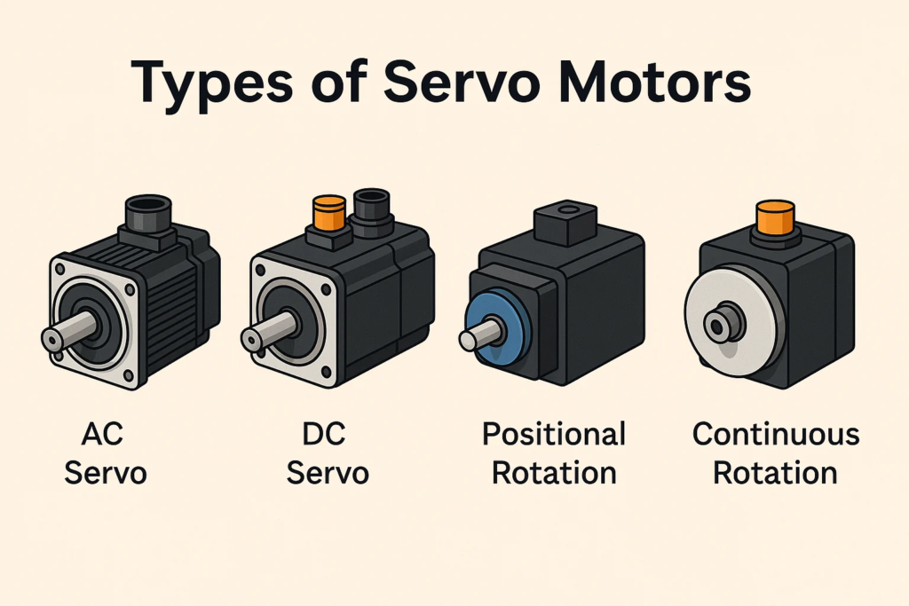
| Type of Servo Motor | Description | Common Applications / Usage |
|---|---|---|
| AC Servo Motor | Runs on alternating current (AC) power. It is used for high-speed and high-power applications. | CNC machines, industrial robots, conveyor systems, packaging machines, factory automation |
| DC Servo Motor | Runs on direct current (DC) power. It provides accurate speed and position control. | Small robots, automated machines, camera systems, medical equipment, laboratory instruments |
| Positional Rotation Servo | Rotates only to a fixed angle, usually between 0° and 180°. It is used for precise position control. | Robotic arms, steering systems, automatic doors, model airplanes, pan-tilt camera mounts |
| Continuous Rotation Servo | Rotates continuously in both clockwise and anticlockwise directions. Speed and direction are controlled by the input signal. | Robot wheels, conveyor belts, mobile robots, automatic vehicles, rotating platforms |
Connection’s
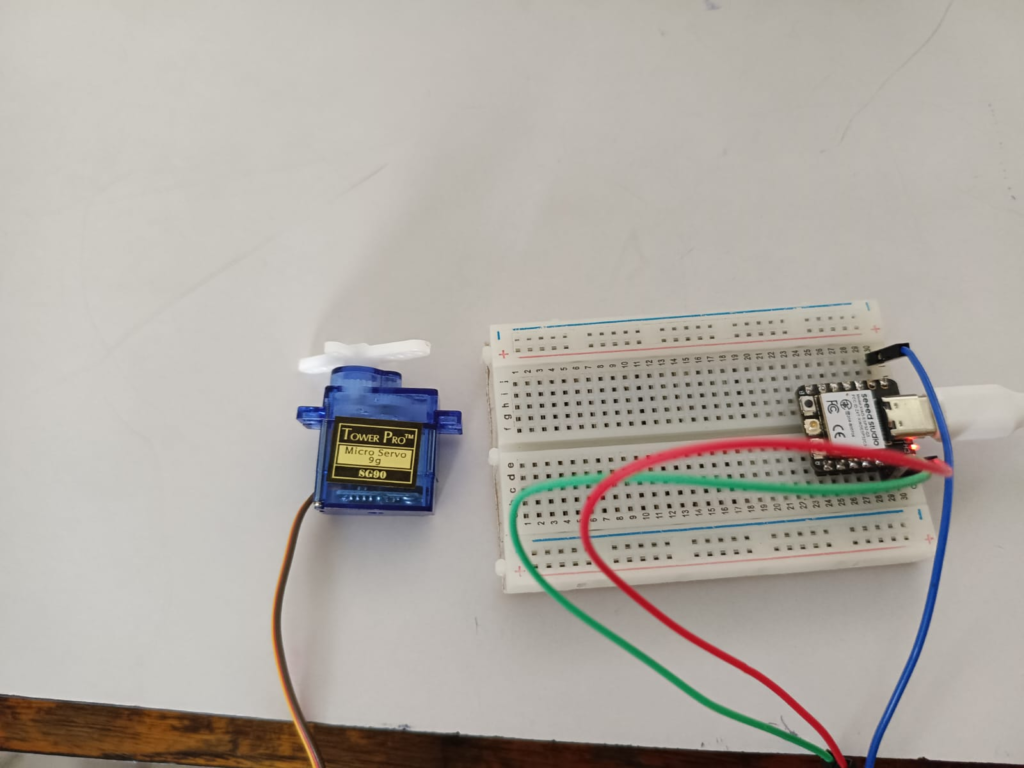
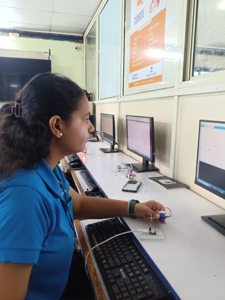
Code Used
#include <ESP32Servo.h>

Servo myServo;

const int servoPin = 2;   // D2 (GPIO2)

void setup() {
  myServo.setPeriodHertz(50);      // Standard servo frequency
  myServo.attach(servoPin, 500, 2400);
}

void loop() {
  // Move from 0° to 180°
  for (int angle = 0; angle <= 180; angle++) {
    myServo.write(angle);
    delay(15);
  }

  // Move from 180° back to 0°
  for (int angle = 180; angle >= 0; angle--) {
    myServo.write(angle);
    delay(15);
  }
}
4.LCD Display
An LCD (Liquid Crystal Display) is a screen that is used to show information like text, numbers, and symbols. It helps us see the output of a device without connecting it to a computer. LCD displays use very little power and are easy to connect with microcontrollers like Arduino and ESP32.
LCD displays are used in many electronic devices such as calculators, digital clocks, home appliances, medical equipment, and electronic meters. In electronics and robotics projects, they are used to display sensor values, temperature, humidity, distance, time, and other important information, making it easy for users to read the Data
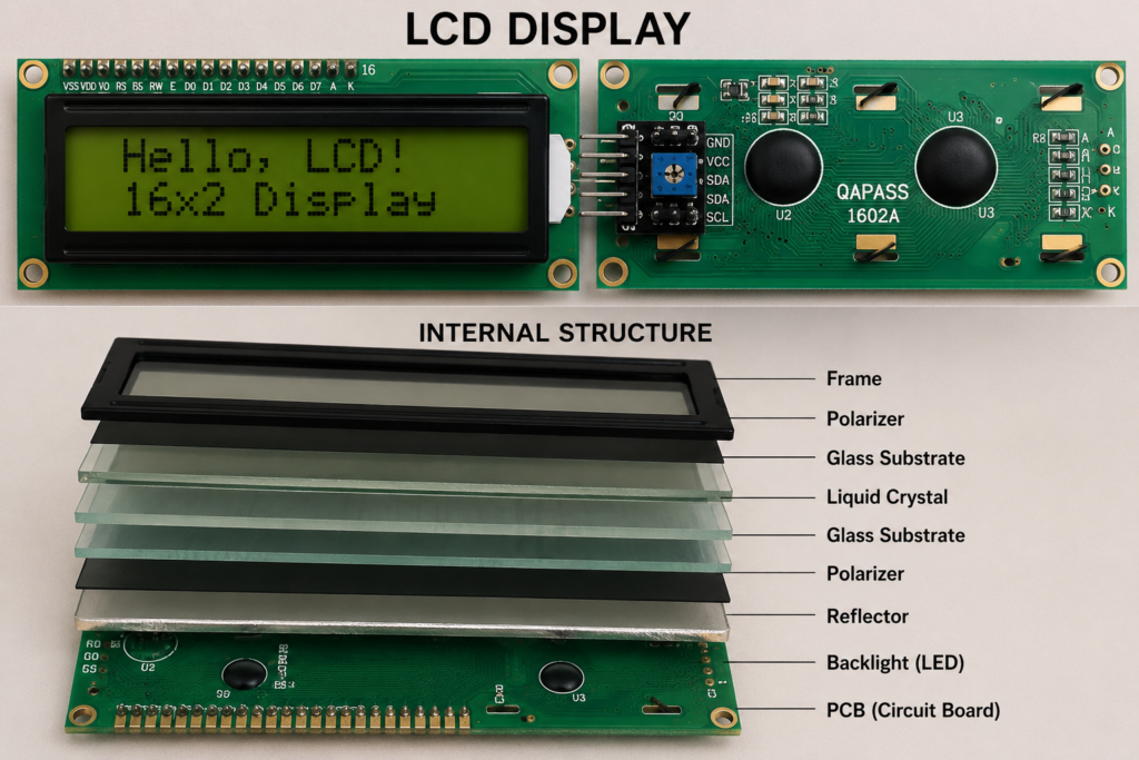
Pin description
| Pin No. | Pin Name | Description |
|---|---|---|
| 1 | VSS | Ground (GND) |
| 2 | VDD | Power supply (+5V) |
| 3 | VO | Adjusts the display contrast |
| 4 | RS | Selects command mode or data mode |
| 5 | RW | Selects Read or Write mode (usually connected to GND for write mode) |
| 6 | E (Enable) | Enables the LCD to receive data |
| 7 | D0 | Data Pin 0 |
| 8 | D1 | Data Pin 1 |
| 9 | D2 | Data Pin 2 |
| 10 | D3 | Data Pin 3 |
| 11 | D4 | Data Pin 4 |
| 12 | D5 | Data Pin 5 |
| 13 | D6 | Data Pin 6 |
| 14 | D7 | Data Pin 7 |
| 15 | A (LED+) | Backlight Anode (+5V) |
| 16 | K (LED−) | Backlight Cathode (GND) |
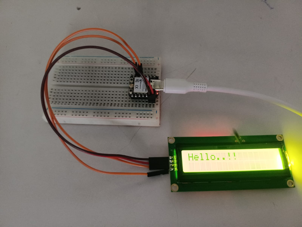
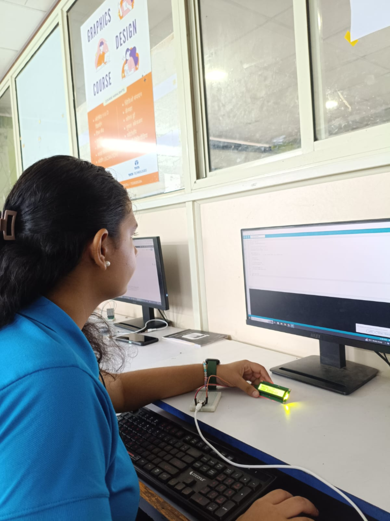
Code
#include <Wire.h>
#include <LiquidCrystal_I2C.h>

// Most I2C LCDs use address 0x27.
// If this doesn't work, try 0x3F.
LiquidCrystal_I2C lcd(0x27, 16, 2);

void setup() {
  Wire.begin(6, 7);      // SDA = GPIO6 (D4), SCL = GPIO7 (D5)

  lcd.init();
  lcd.backlight();

  lcd.setCursor(0, 0);
  lcd.print("Hello...!!");

  lcd.setCursor(0, 1);
  lcd.print("XIAO ESP32-C3");
}

void loop() {
}
5.Dot Matrix
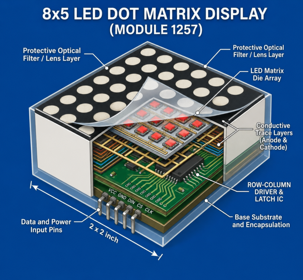
A dot matrix display is an electronic output device made up of many small LED lights arranged in rows and columns. By turning different LEDs on and off, it can display letters, numbers, symbols, and simple images. It is easy to control using a microcontroller like Arduino or ESP32.
Dot matrix displays are used to show information in a clear and simple way. They are commonly found in digital clocks, bus and railway display boards, scoreboards, advertising signs, and electronic notice boards. They can display scrolling text, messages, and animations.
A dot matrix display is popular because it uses very little power, is easy to program, and can display different types of information. It is widely used in electronics projects, schools, industries, and public information systems to show messages and visual data clearly.
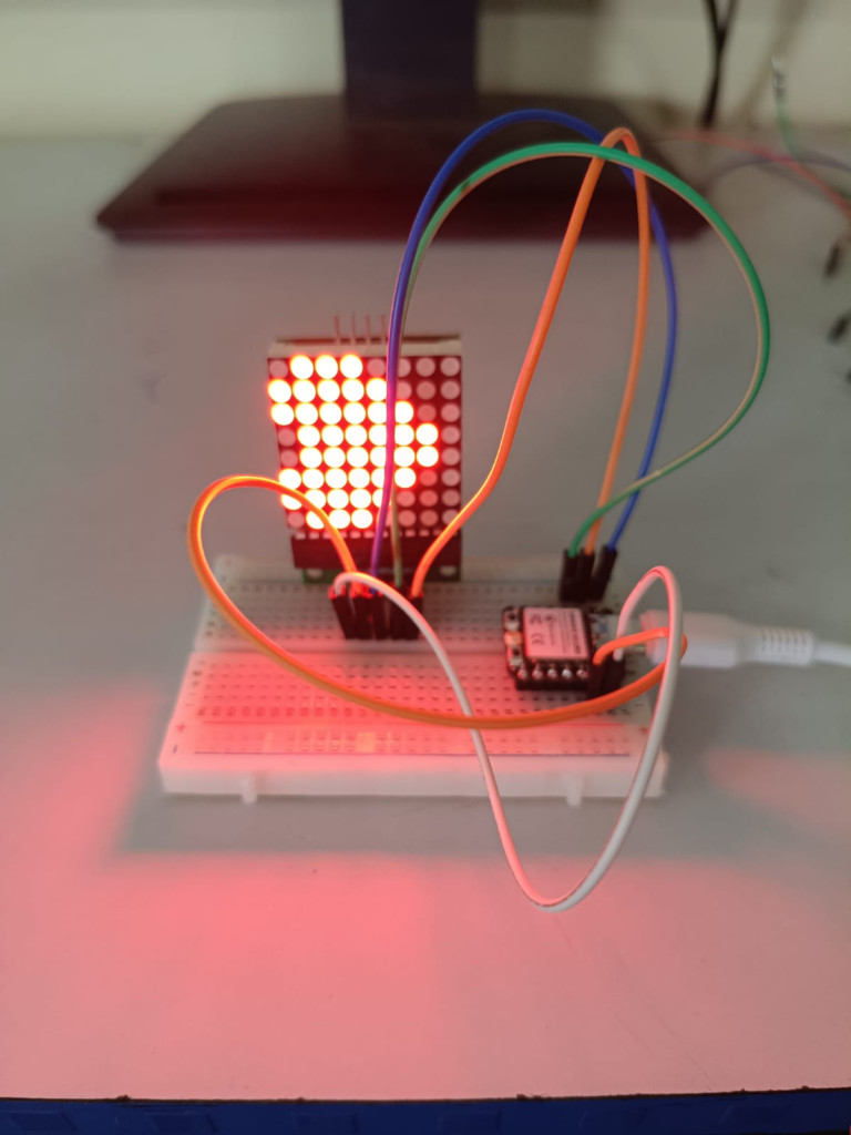
#include <MD_MAX72xx.h>
#include <SPI.h>

#define HARDWARE_TYPE MD_MAX72XX::FC16_HW
#define MAX_DEVICES 1

#define DATA_PIN 2
#define CLK_PIN 3
#define CS_PIN 4

MD_MAX72XX matrix = MD_MAX72XX(HARDWARE_TYPE, DATA_PIN, CLK_PIN, CS_PIN, MAX_DEVICES);

uint8_t heart[8] = {
  B01100110,
  B11111111,
  B11111111,
  B11111111,
  B01111110,
  B00111100,
  B00011000,
  B00000000
};

void setup()
{
  matrix.begin();
  matrix.control(MD_MAX72XX::INTENSITY, 8);
  matrix.clear();

  for (int i = 0; i < 8; i++)
  {
    matrix.setRow(0, i, heart[i]);
  }
}

void loop()
{
}
6.Buzzer
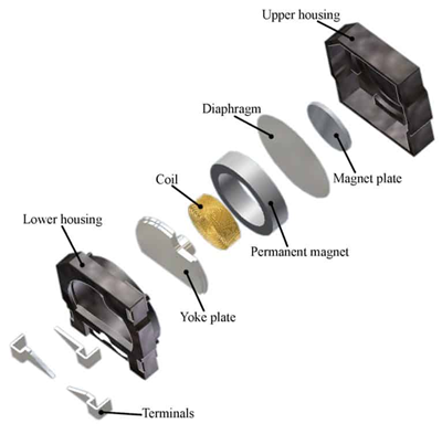
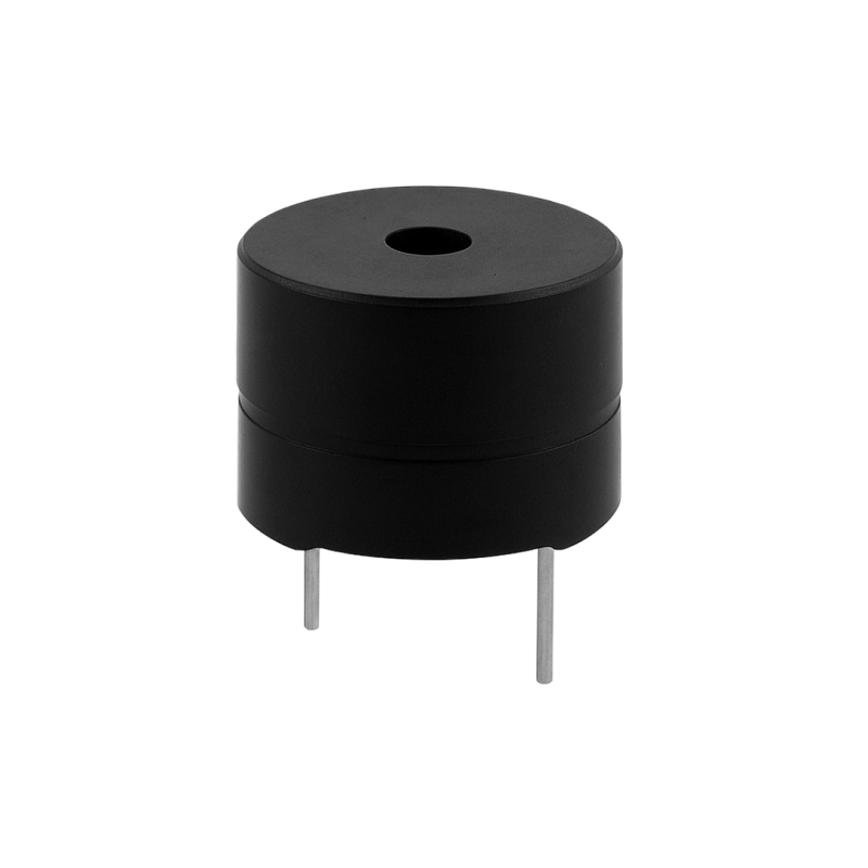
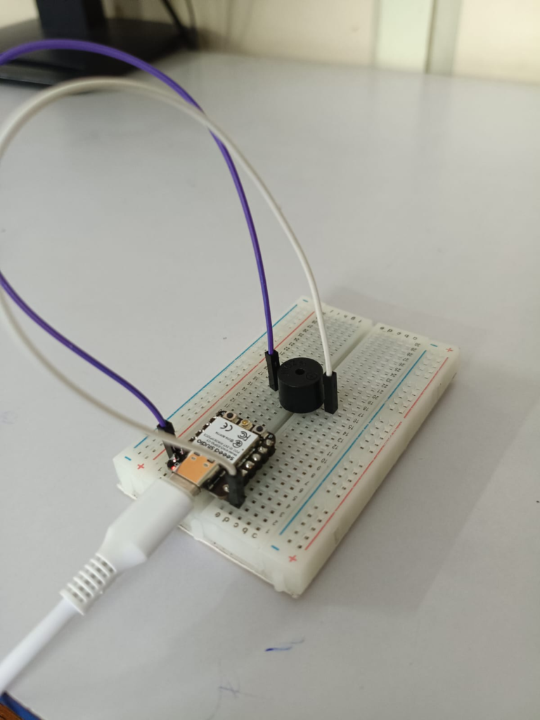
A buzzer is a simple electronic output device that produces sound when electricity is supplied to it. It is used to give alerts, warnings, or notifications. Buzzers are small, inexpensive, and easy to connect with microcontrollers like Arduino and ESP32, making them very common in electronics projects.
There are two main types of buzzers: active buzzers and passive buzzers. An active buzzer has a built-in oscillator, so it produces a sound as soon as power is applied. A passive buzzer does not have an oscillator and needs a changing electrical signal from a microcontroller to create different tones and melodies.
Buzzers are used in many everyday devices such as alarm systems, doorbells, timers, toys, microwave ovens, and home appliances. They help attract attention by making a clear sound, making them useful for indicating errors, alarms, reminders, or when a task has been completed.


7. Relay Module
exaplin what is relay modul;e in 2-3 paragraph
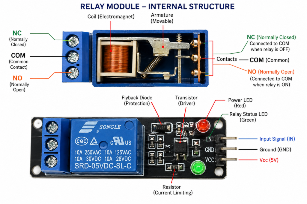
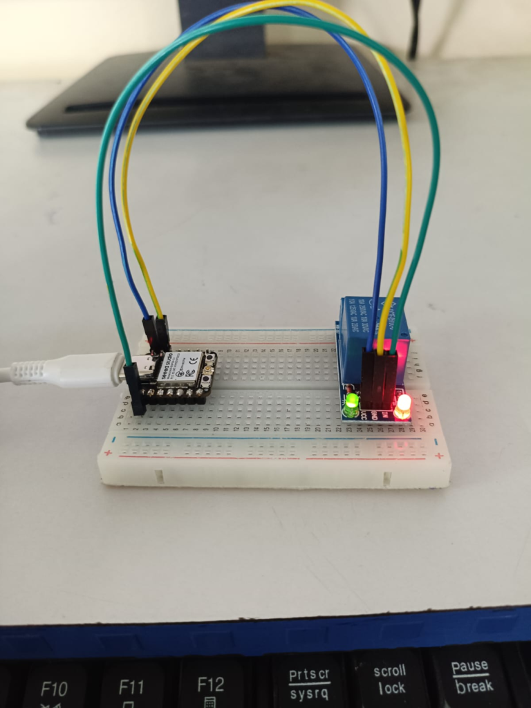
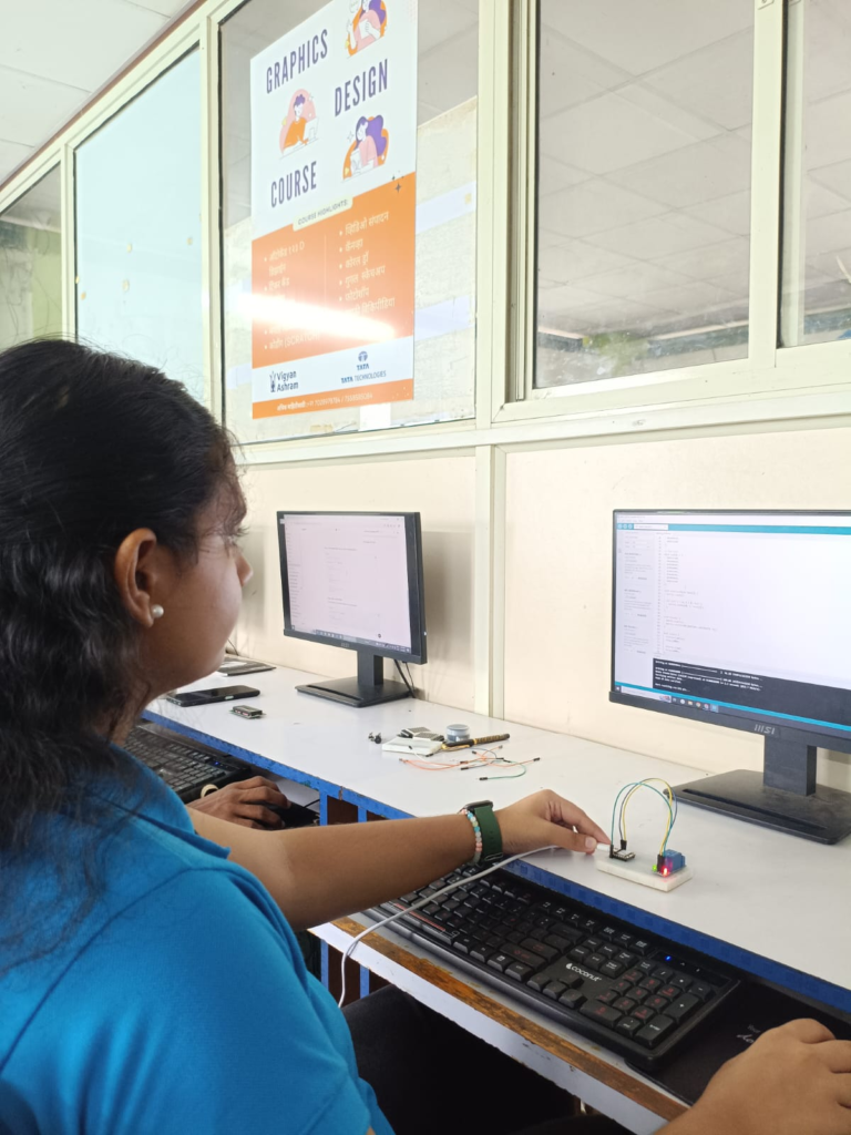
A relay module is an electronic switching device that allows a microcontroller such as an Arduino or XIAO ESP32-C3 to control high-voltage or high-current electrical devices safely. It works like an automatic switch that turns devices ON or OFF when it receives a small electrical signal from the microcontroller. This makes it possible to control appliances without directly connecting them to the microcontroller.
A relay module is commonly used in home automation, smart lighting, motor control, security systems, and IoT projects. It can control devices such as lights, fans, water pumps, and other electrical appliances. The relay provides electrical isolation between the low-voltage control circuit and the high-voltage load, helping to protect the microcontroller from damage.
// Relay Module with XIAO ESP32-C3

#define RELAY_PIN 4   // GPIO4 (D2)

void setup() {
  pinMode(RELAY_PIN, OUTPUT);
}

void loop() {
  // Relay ON
  digitalWrite(RELAY_PIN, LOW);   // Active LOW relay
  delay(1000);

  // Relay OFF
  digitalWrite(RELAY_PIN, HIGH);
  delay(1000);
8. DC Motor
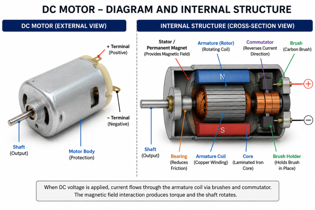
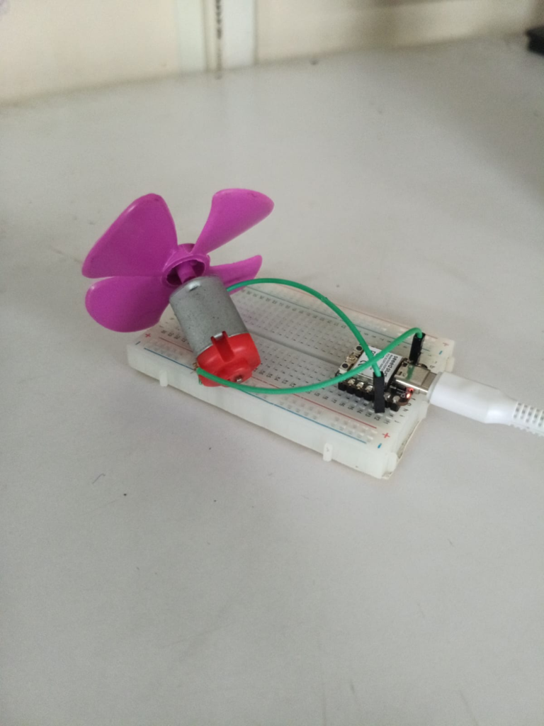
A DC motor (Direct Current motor) is an electrical device that converts electrical energy into mechanical movement. When a DC power supply, such as a battery, is connected to the motor, it starts rotating. The motor uses magnets and a coil of wire to produce motion, making it useful for many small electronic and mechanical projects.
DC motors are widely used in robots, toy cars, electric fans, water pumps, conveyor belts, and other automatic machines. They are popular because they are simple to use, easy to control, and can run at different speeds by changing the supplied voltage. DC motors are commonly used in Arduino, ESP32, and other microcontroller-based projects to create movement and perform different tasks.
#define MOTOR_PIN 3   // GPIO 3

void setup() {
  pinMode(MOTOR_PIN, OUTPUT);
}

void loop() {
  digitalWrite(MOTOR_PIN, LOW);   // Motor ON
}