Introduction
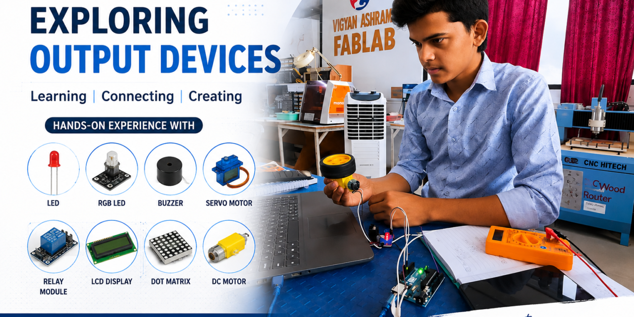
In this week, I learned about different output devices used in embedded systems and how they work with a microcontroller. Output devices receive signals from the microcontroller and convert them into physical actions such as light, sound, motion, or visual display. I studied the working principle, features, and applications of different output devices, including LEDs, buzzers, relays, DC motors, servo motors, stepper motors, OLED displays, and LCD displays. I also learned how these devices are connected to a microcontroller and how they are controlled through programming. This hands-on learning improved my understanding of embedded systems and showed me how output devices are used in real-world projects and automation systems.
What is an Output Device?
An output device is an electronic component that receives signals from a microcontroller or computer and converts them into a physical action. It helps the system interact with the outside world by producing outputs such as light, sound, movement, or visual information. Output devices are commonly used in embedded systems, automation, robotics, and IoT projects to perform different tasks based on the program.

Indiviual Assignment
Output Devices I Used
1.LED (Light Emitting Diode)
A Light Emitting Diode (LED) is an electronic output device that produces light when an electric current passes through it. It is one of the most commonly used output devices in embedded systems and electronic projects. LEDs consume very little power, respond quickly, and have a long operating life. They are available in different colors such as red, green, blue, yellow, and white. LEDs are widely used as status indicators, signal lights, decorative lighting, display panels, and in automation and IoT applications.

Types of LED

Connection of led with Xiao ESP32-C3
After learning about different output devices, I performed my first practical by blinking an LED using the Seeed XIAO ESP32-C3 development board. I connected the LED to the board with a current-limiting resistor and wrote a simple program in the Arduino IDE. The program turned the LED ON and OFF repeatedly with a short delay. This activity helped me understand how a microcontroller controls an output device using digital output pins. It also improved my programming and circuit-building skills.


CODE
// LED Blink using Seeed XIAO ESP32-C3

const int ledPin = 2;   // Connect LED to GPIO 2

void setup() {
  pinMode(ledPin, OUTPUT);
}

void loop() {
  digitalWrite(ledPin, HIGH);   // LED ON
  delay(1000);                  // Wait for 1 second

  digitalWrite(ledPin, LOW);    // LED OFF
  delay(1000);                  // Wait for 1 second
}
2. RGB LED
An RGB LED (Red, Green, Blue Light Emitting Diode) is an electronic output device that can produce different colors by combining red, green, and blue light. It contains three LEDs inside a single package and can display a wide range of colors by adjusting the brightness of each LED. RGB LEDs are easy to interface with microcontrollers and are widely used in embedded systems, IoT projects, decorative lighting, and status indication.

Connection of RGB LED with XIAO ESP32-C3
An RGB LED can be connected to the Seeed XIAO ESP32-C3 using three GPIO pins. The Red, Green, and Blue pins are connected to separate GPIO pins through 220Ω resistors, while the common pin is connected according to the LED type. The ESP32-C3 controls the brightness of each color using digital or PWM signals, allowing different colors to be produced by mixing the red, green, and blue LEDs.
Connection Table (Common Cathode RGB LED)
| RGB LED Pin | Seeed XIAO ESP32-C3 |
|---|---|
| Red (R) | D0 (GPIO2) |
| Green (G) | D1 (GPIO3) |
| Blue (B) | D2 (GPIO4) |
| Common Cathode (–) | GND |
Note: Connect a 220Ω resistor in series with each Red, Green, and Blue pin to protect the LED. If you are using a Common Anode RGB LED, connect the common pin to 3.3V instead of GND, and the control logic will be reversed.


CODE
// External RGB LED Control using Serial Monitor
// Board: Seeed XIAO ESP32-C3

const int RED = 2;      // D0 (GPIO2)
const int GREEN = 3;    // D1 (GPIO3)
const int BLUE = 4;     // D2 (GPIO4)

void setup() {
  Serial.begin(115200);

  pinMode(RED, OUTPUT);
  pinMode(GREEN, OUTPUT);
  pinMode(BLUE, OUTPUT);

  // Turn OFF all LEDs
  digitalWrite(RED, LOW);
  digitalWrite(GREEN, LOW);
  digitalWrite(BLUE, LOW);

  Serial.println("=== RGB LED Control ===");
  Serial.println("Available Commands:");
  Serial.println("RED");
  Serial.println("GREEN");
  Serial.println("BLUE");
  Serial.println("YELLOW");
  Serial.println("CYAN");
  Serial.println("PURPLE");
  Serial.println("WHITE");
  Serial.println("OFF");
}

void loop() {
  if (Serial.available()) {

    String color = Serial.readStringUntil('\n');
    color.trim();
    color.toUpperCase();

    // Turn OFF all LEDs
    digitalWrite(RED, LOW);
    digitalWrite(GREEN, LOW);
    digitalWrite(BLUE, LOW);

    if (color == "RED") {
      digitalWrite(RED, HIGH);
    }
    else if (color == "GREEN") {
      digitalWrite(GREEN, HIGH);
    }
    else if (color == "BLUE") {
      digitalWrite(BLUE, HIGH);
    }
    else if (color == "YELLOW") {
      digitalWrite(RED, HIGH);
      digitalWrite(GREEN, HIGH);
    }
    else if (color == "CYAN") {
      digitalWrite(GREEN, HIGH);
      digitalWrite(BLUE, HIGH);
    }
    else if (color == "PURPLE") {
      digitalWrite(RED, HIGH);
      digitalWrite(BLUE, HIGH);
    }
    else if (color == "WHITE") {
      digitalWrite(RED, HIGH);
      digitalWrite(GREEN, HIGH);
      digitalWrite(BLUE, HIGH);
    }
    else if (color == "OFF") {
      // LED OFF
    }
    else {
      Serial.println("Invalid Command!");
      Serial.println("Use: RED, GREEN, BLUE, YELLOW, CYAN, PURPLE, WHITE or OFF");
    }
  }
}
3.Servo Motor
A servo motor is an output device that is used to control the position of an object with high accuracy. It can rotate to a specific angle, usually between 0° and 180°, based on the control signal received from a microcontroller. A servo motor contains a DC motor, gears, a control circuit, and a feedback mechanism to achieve precise movement. It is easy to control using PWM (Pulse Width Modulation) signals, making it suitable for many embedded system and robotics projects.

Connection of Servo Motor with Xiao ESP32-C3
A servo motor can be easily connected to the Seeed XIAO ESP32-C3 using three wires. The VCC (Red) wire is connected to the 5V pin to provide power. The GND (Brown or Black) wire is connected to the GND pin. The Signal (Orange or Yellow) wire is connected to a PWM-capable GPIO pin (such as GPIO 2 or GPIO 3). The ESP32-C3 sends PWM (Pulse Width Modulation) signals through the signal pin to control the servo motor’s position. By changing the PWM signal, the servo motor can rotate to different angles between 0° and 180°.
Connections
| Servo Motor Pin | Seeed XIAO ESP32-C3 Pin |
|---|---|
| VCC (Red) | 5V |
| GND (Brown/Black) | GND |
| Signal (Orange/Yellow) | GPIO 2 (or any PWM GPIO) |


CODE
#include <ESP32Servo.h>

Servo myServo;

const int servoPin = 2;   // Servo signal pin connected to GPIO 2

void setup() {
  Serial.begin(115200);

  myServo.attach(servoPin);
  myServo.write(90);   // Start at 90°

  Serial.println("=== Servo Motor Control ===");
  Serial.println("Enter angle between 0 and 180:");
}

void loop() {

  if (Serial.available()) {

    int angle = Serial.parseInt();

    if (angle >= 0 && angle <= 180) {
      myServo.write(angle);

      Serial.print("Servo Angle: ");
      Serial.print(angle);
      Serial.println(" degrees");
    }
    else {
      Serial.println("Invalid Angle! Enter a value between 0 and 180.");
    }

    while (Serial.available()) {
      Serial.read();
    }
  }
}
Types of Display
Display devices are output devices used to show text, numbers, symbols, images, and graphics. Common types of displays include LED, 7-Segment, LCD, OLED, TFT, Dot Matrix, E-Paper, and VFD. Each display has different features and is selected based on the requirements of the application, such as power consumption, display quality, and functionality.

4. LCD Display (16×2)
An LCD (Liquid Crystal Display) is an electronic output device used to display text, numbers, and simple symbols. It is one of the most commonly used display devices in embedded systems and Arduino projects. A 16×2 LCD can display 16 characters in each line and has 2 rows, allowing a total of 32 characters to be displayed at a time. It consumes very little power and provides a simple way to display information from a microcontroller.
The LCD works by receiving data from a microcontroller and displaying it on the screen. It is widely used in embedded systems because it is easy to interface and provides clear output for users.

Connection of LCD Display (16×2) with Xiao ESP32-C3
A 16×2 LCD Display can be connected to the Seeed XIAO ESP32-C3 using the I2C interface. The I2C module reduces the number of wires required, making the connection simple and easy. The LCD receives data from the ESP32-C3 through the SDA and SCL pins and displays text, numbers, and symbols on the screen.
Connections
| LCD (I2C Module) | Seeed XIAO ESP32-C3 |
|---|---|
| VCC | 5V |
| GND | GND |
| SDA | GPIO 6 (SDA) |
| SCL | GPIO 7 (SCL) |
The ESP32-C3 sends display data through the I2C communication protocol using the SDA and SCL pins. The LCD then displays the received information on its screen.


CODE
#include <Wire.h>
#include <LiquidCrystal_I2C.h>

// LCD I2C Address (Usually 0x27 or 0x3F)
LiquidCrystal_I2C lcd(0x27, 16, 2);

void setup() {
  Wire.begin(6, 7);   // SDA = GPIO 6, SCL = GPIO 7

  lcd.init();
  lcd.backlight();

  lcd.setCursor(0, 0);
  lcd.print("Hello World!");

  lcd.setCursor(0, 1);
  lcd.print("XIAO ESP32-C3");
}

void loop() {

}
5. MAX7219 Dot matrix display
The MAX7219 Dot Matrix Display is an electronic output device used to display text, numbers, symbols, and simple animations. It consists of an 8×8 LED matrix controlled by the MAX7219 driver IC, which makes it easy to interface with a microcontroller using only a few pins. Multiple MAX7219 modules can also be connected together to create longer scrolling displays.
The MAX7219 driver handles the LED scanning and brightness control automatically, reducing the workload of the microcontroller. Because of its simple wiring and low power consumption, it is widely used in embedded systems, IoT projects, and digital display applications.

Connection of Dot matrix display with Xiao ESP32-C3
The MAX7219 Dot Matrix Display can be connected to the Seeed XIAO ESP32-C3 using the SPI communication interface. The MAX7219 driver IC receives data from the ESP32-C3 through the DIN, CLK, and CS pins. The driver IC controls all 64 LEDs of the 8×8 dot matrix, allowing text, symbols, and animations to be displayed with only a few connections.
Connections
| MAX7219 Dot Matrix Pin | Seeed XIAO ESP32-C3 Pin |
|---|---|
| VCC | 5V |
| GND | GND |
| DIN | GPIO 10 (MOSI) |
| CS | GPIO 9 |
| CLK | GPIO 8 (SCK) |
The ESP32-C3 sends display data through the SPI interface. The MAX7219 driver IC receives the data and controls the LEDs in the dot matrix to display the required characters or patterns.


CODE
#include <MD_Parola.h>
#include <MD_MAX72XX.h>
#include <SPI.h>

#define HARDWARE_TYPE MD_MAX72XX::FC16_HW
#define MAX_DEVICES 1

#define DATA_PIN 2   // DIN
#define CLK_PIN  3    // CLK
#define CS_PIN   4    // CS

MD_Parola matrix = MD_Parola(HARDWARE_TYPE, DATA_PIN, CLK_PIN, CS_PIN, MAX_DEVICES);

void setup() {
  Serial.begin(115200);

  matrix.begin();
  matrix.setIntensity(5);
  matrix.displayClear();

  Serial.println("=== MAX7219 Dot Matrix ===");
  Serial.println("Type any text and press Enter:");
}

void loop() {

  if (Serial.available()) {

    String text = Serial.readStringUntil('\n');
    text.trim();

    matrix.displayClear();
    matrix.displayScroll(text.c_str(), PA_LEFT, PA_SCROLL_LEFT, 80);

    while (!matrix.displayAnimate()) {
      // Wait until scrolling is complete
    }

    matrix.displayReset();
  }
}
6. 7-Segment Dispaly
A 7-Segment Display is an electronic output device used to display numbers from 0 to 9. It consists of seven LED segments arranged in the shape of the number 8. By turning different segments ON and OFF, different numbers can be displayed. It is easy to interface with microcontrollers and is widely used in embedded systems because of its simple design and low power consumption.

Connection of 7-Segment Display with XIAO ESP32-C3
A 7-Segment Display can be connected to the Seeed XIAO ESP32-C3 using its GPIO pins. Each segment (a–g and dp) is controlled by a separate GPIO pin through a 220Ω current-limiting resistor to protect the LEDs. The common pin is connected according to the display type: GND for a Common Cathode display and 3.3V for a Common Anode display. By turning the GPIO pins HIGH or LOW, the microcontroller can control each segment and display numbers from 0 to 9.
Connection Table (Common Cathode)
| 7-Segment Pin | Seeed XIAO ESP32-C3 |
|---|---|
| a | D0 (GPIO2) |
| b | D1 (GPIO3) |
| c | D2 (GPIO4) |
| d | D3 (GPIO5) |
| e | D4 (GPIO6) |
| f | D5 (GPIO7) |
| g | D6 (GPIO21) |
| dp | D7 (GPIO20) (Optional) |
| COM | GND |
Note: Connect a 220Ω resistor in series with each segment pin (a–g and dp) to limit the current and protect the LEDs.
CODE
// 7-Segment Display with Seeed XIAO ESP32-C3
// Common Cathode Display

// Segment pins
const int a = 2;    // D0
const int b = 3;    // D1
const int c = 4;    // D2
const int d = 5;    // D3
const int e = 6;    // D4
const int f = 7;    // D5
const int g = 21;   // D6

void setup() {
  pinMode(a, OUTPUT);
  pinMode(b, OUTPUT);
  pinMode(c, OUTPUT);
  pinMode(d, OUTPUT);
  pinMode(e, OUTPUT);
  pinMode(f, OUTPUT);
  pinMode(g, OUTPUT);
}

void loop() {
  display0(); delay(1000);
  display1(); delay(1000);
  display2(); delay(1000);
  display3(); delay(1000);
  display4(); delay(1000);
  display5(); delay(1000);
  display6(); delay(1000);
  display7(); delay(1000);
  display8(); delay(1000);
  display9(); delay(1000);
}

// Functions to display numbers

void display0() {
  digitalWrite(a,HIGH); digitalWrite(b,HIGH); digitalWrite(c,HIGH);
  digitalWrite(d,HIGH); digitalWrite(e,HIGH); digitalWrite(f,HIGH);
  digitalWrite(g,LOW);
}

void display1() {
  digitalWrite(a,LOW); digitalWrite(b,HIGH); digitalWrite(c,HIGH);
  digitalWrite(d,LOW); digitalWrite(e,LOW); digitalWrite(f,LOW);
  digitalWrite(g,LOW);
}

void display2() {
  digitalWrite(a,HIGH); digitalWrite(b,HIGH); digitalWrite(c,LOW);
  digitalWrite(d,HIGH); digitalWrite(e,HIGH); digitalWrite(f,LOW);
  digitalWrite(g,HIGH);
}

void display3() {
  digitalWrite(a,HIGH); digitalWrite(b,HIGH); digitalWrite(c,HIGH);
  digitalWrite(d,HIGH); digitalWrite(e,LOW); digitalWrite(f,LOW);
  digitalWrite(g,HIGH);
}

void display4() {
  digitalWrite(a,LOW); digitalWrite(b,HIGH); digitalWrite(c,HIGH);
  digitalWrite(d,LOW); digitalWrite(e,LOW); digitalWrite(f,HIGH);
  digitalWrite(g,HIGH);
}

void display5() {
  digitalWrite(a,HIGH); digitalWrite(b,LOW); digitalWrite(c,HIGH);
  digitalWrite(d,HIGH); digitalWrite(e,LOW); digitalWrite(f,HIGH);
  digitalWrite(g,HIGH);
}

void display6() {
  digitalWrite(a,HIGH); digitalWrite(b,LOW); digitalWrite(c,HIGH);
  digitalWrite(d,HIGH); digitalWrite(e,HIGH); digitalWrite(f,HIGH);
  digitalWrite(g,HIGH);
}

void display7() {
  digitalWrite(a,HIGH); digitalWrite(b,HIGH); digitalWrite(c,HIGH);
  digitalWrite(d,LOW); digitalWrite(e,LOW); digitalWrite(f,LOW);
  digitalWrite(g,LOW);
}

void display8() {
  digitalWrite(a,HIGH); digitalWrite(b,HIGH); digitalWrite(c,HIGH);
  digitalWrite(d,HIGH); digitalWrite(e,HIGH); digitalWrite(f,HIGH);
  digitalWrite(g,HIGH);
}

void display9() {
  digitalWrite(a,HIGH); digitalWrite(b,HIGH); digitalWrite(c,HIGH);
  digitalWrite(d,HIGH); digitalWrite(e,LOW); digitalWrite(f,HIGH);
  digitalWrite(g,HIGH);
}
7. OLED Display
An OLED (Organic Light Emitting Diode) Display is an electronic output device used to display text, numbers, images, and graphics. Unlike an LCD, an OLED display does not require a backlight because each pixel produces its own light. This provides high brightness, excellent contrast, wide viewing angles, and low power consumption. OLED displays are easy to interface with microcontrollers using the I2C communication protocol and are widely used in embedded systems, IoT projects, smart devices, and wearable electronics.

Connection of OLED Display with XIAO ESP32-C3
An OLED Display (SSD1306, I2C) can be easily connected to the Seeed XIAO ESP32-C3 using the I2C communication protocol. It requires only four connections: VCC, GND, SDA, and SCL. The XIAO ESP32-C3 sends data to the OLED through the SDA and SCL pins, allowing it to display text, numbers, symbols, and graphics. Because it uses I2C communication, only two GPIO pins are needed, making the connection simple and efficient.
Connection Table
| OLED Display Pin | Seeed XIAO ESP32-C3 |
|---|---|
| VCC | 3.3V |
| GND | GND |
| SDA | D4 (GPIO6) |
| SCL | D5 (GPIO7) |
Note: Most 0.96-inch SSD1306 OLED displays work with 3.3V and use the default I2C address 0x3C.
CODE
// OLED Display with Seeed XIAO ESP32-C3
// SSD1306 OLED (128x64 I2C)

#include <Wire.h>
#include <Adafruit_GFX.h>
#include <Adafruit_SSD1306.h>

#define SCREEN_WIDTH 128
#define SCREEN_HEIGHT 64
#define OLED_RESET -1

Adafruit_SSD1306 display(SCREEN_WIDTH, SCREEN_HEIGHT, &Wire, OLED_RESET);

void setup() {
  // SDA = GPIO6 (D4), SCL = GPIO7 (D5)
  Wire.begin(6, 7);

  // Initialize OLED
  if (!display.begin(SSD1306_SWITCHCAPVCC, 0x3C)) {
    while (true);
  }

  display.clearDisplay();

  // Display Text
  display.setTextSize(2);
  display.setTextColor(SSD1306_WHITE);
  display.setCursor(10, 20);
  display.println("Hello!");
  display.display();
}

void loop() {
  // Nothing to repeat
}
8. Buzzer
A buzzer is an electronic output device that produces sound when it receives an electrical signal from a microcontroller or other electronic circuit. It is commonly used to provide audio alerts, warnings, and notifications in embedded systems. Buzzers are simple to use, consume very little power, and are available in different types such as active and passive buzzers. They are widely used in automation, security systems, and electronic projects.

Connection of Buzzer with XIAO ESP32-C3
A buzzer can be easily connected to the Seeed XIAO ESP32-C3 using two or three pins, depending on the type of buzzer. The ESP32-C3 sends a digital signal to the buzzer, which produces sound. Buzzers are commonly used for alarms, notifications, and warning systems in embedded projects.
Connections (Active Buzzer)
| Buzzer Pin | Seeed XIAO ESP32-C3 Pin |
|---|---|
| VCC (+) | 3.3V |
| GND (−) | GND |
| Signal (S) | GPIO 2 |
The ESP32-C3 sends a HIGH or LOW signal through the GPIO pin to control the buzzer. When the signal is HIGH, the buzzer produces sound, and when the signal is LOW, the buzzer stops.


CODE
const int buzzerPin = 2;   // Buzzer connected to GPIO 2

void setup() {
  pinMode(buzzerPin, OUTPUT);
  digitalWrite(buzzerPin, LOW);

  Serial.begin(115200);

  Serial.println("=== Buzzer Control ===");
  Serial.println("Type ON to turn ON the buzzer");
  Serial.println("Type OFF to turn OFF the buzzer");
}

void loop() {

  if (Serial.available()) {

    String command = Serial.readStringUntil('\n');
    command.trim();
    command.toUpperCase();

    if (command == "ON") {
      digitalWrite(buzzerPin, HIGH);
      Serial.println("Buzzer ON");
    }
    else if (command == "OFF") {
      digitalWrite(buzzerPin, LOW);
      Serial.println("Buzzer OFF");
    }
    else {
      Serial.println("Invalid Command! Type ON or OFF.");
    }
  }
}
9. Relay Module
A Relay Module is an electronic output device used to control high-voltage or high-current electrical devices using a low-voltage signal from a microcontroller. It works as an electrically operated switch that allows the microcontroller to safely turn external devices ON or OFF. Relay modules provide electrical isolation between the control circuit and the load, making them suitable for controlling AC and DC appliances. They are widely used in embedded systems, home automation, industrial control, and IoT projects.

Connection of Relay Module with XIAO ESP32-C3
A Relay Module can be connected to the Seeed XIAO ESP32-C3 using one digital GPIO pin. The relay module receives a control signal from the microcontroller through the IN pin, which switches the relay ON or OFF. The relay is powered using 5V (or the module’s required supply voltage), while the XIAO ESP32-C3 and the relay module must share a common GND. The relay output terminals (COM, NO, and NC) are used to connect and control external AC or DC loads safely.
Connection Table
| Relay Module Pin | Seeed XIAO ESP32-C3 |
|---|---|
| VCC | 5V |
| GND | GND |
| IN | D2 (GPIO4) |
Relay Output Terminals
| Relay Terminal | Function |
|---|---|
| COM | Common Terminal |
| NO | Normally Open |
| NC | Normally Closed |
Note: Many relay modules require a 5V supply to operate reliably. The IN pin can usually be controlled by the XIAO ESP32-C3’s 3.3V GPIO signal, but this depends on the specific relay module being used.


CODE
// Relay Module with Seeed XIAO ESP32-C3

const int relayPin = 4;   // D2 (GPIO4)

void setup() {
  pinMode(relayPin, OUTPUT);

  // Relay OFF at startup
  digitalWrite(relayPin, LOW);
}

void loop() {
  // Relay ON
  digitalWrite(relayPin, HIGH);
  delay(2000);

  // Relay OFF
  digitalWrite(relayPin, LOW);
  delay(2000);
}
Group Assignment
BO Motor (Battery Operated Motor)
A BO (Battery Operated) Motor is a small DC geared motor commonly used in robotics and embedded system projects. It operates on a low DC voltage, typically 3V to 12V, and provides high torque at a low speed. The built-in gearbox reduces the motor speed while increasing its torque, making it suitable for driving wheels and moving small robotic vehicles. A BO motor is easy to interface with motor driver modules and microcontrollers, making it an ideal choice for beginners and educational projects.

Connection of BO Motor with Arduino Using L298N Motor Driver
As a group assignment, we connected two BO motors to an Arduino Uno using an L298N motor driver module. The L298N driver was used to control the direction and speed of the motors. We connected the motor terminals to the output pins of the driver, while the control pins were connected to the Arduino digital pins.
After completing the connections, we attached wheels to both BO motors and uploaded the Arduino program. The motors rotated smoothly, causing the wheels to move forward and backward based on the program. This activity helped us understand how a motor driver controls DC motors and improved our practical skills in motor interfacing, wiring, and testing.
Pin Configuration of BO Motor with Arduino Uno and L298N Motor Driver
| L298N Pin | Arduino Uno |
|---|---|
| IN1 | D8 |
| IN2 | D9 |
| IN3 | D10 |
| IN4 | D11 |
| ENA | D5 (PWM) |
| ENB | D6 (PWM) |
| GND | GND |
Power Connections
| L298N Pin | Connection |
|---|---|
| 12V (VIN) | External Battery (6V–12V) Positive |
| GND | Battery Negative & Arduino GND (Common Ground) |
| 5V | Arduino 5V (if using the onboard 5V regulator) |
Note: Connect the battery GND and Arduino GND together (common ground). This allows the Arduino and L298N motor driver to communicate correctly.


Checking the voltage of motor


Overall Experience
This week, I gained practical knowledge about different output devices and learned how to interface them with the Seeed XIAO ESP32-C3 and Arduino Uno. I worked with components such as LEDs, RGB LED, buzzer, servo motor, relay module, LCD display, OLED display, 7-segment display, MAX7219 dot matrix display, and BO motor. Through these hands-on activities, I improved my skills in circuit connections, programming, debugging, and hardware interfacing, which gave me a better understanding of embedded systems and electronics.