Introduction
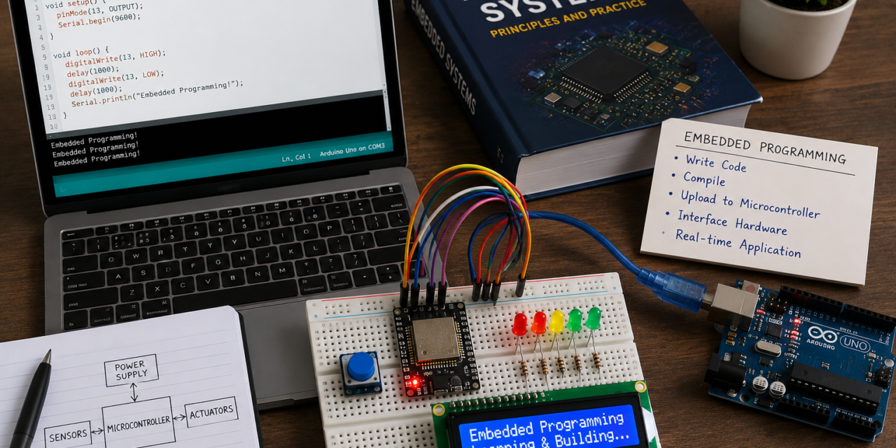
In this week of Fab Academy, we learned the basics of Embedded Programming and Embedded Systems. We studied the difference between Embedded Programming and Embedded Systems, along with the concepts of Microcontrollers and Microprocessors, their types, and the differences between them. We also learned about Thonny IDE, including its installation process for programming microcontrollers. Finally, we completed both the group assignment and the individual assignment, where we applied the concepts learned during the week through practical activities.
Embedded Programming
Embedded programming is the process of writing software for embedded systems. It involves creating programs that control the hardware and enable a device to perform a specific task. Embedded programming is commonly done using languages such as C and C++. It is used in devices like home appliances, automobiles, medical equipment, and industrial machines. The goal is to ensure the device operates efficiently, reliably, and in real time.

Embedded System
An embedded system is a small computer built into a larger device to perform a specific task. It consists of both hardware and software that work together to control the device’s functions. Unlike a general-purpose computer, an embedded system is designed for one dedicated purpose. Embedded systems are commonly found in appliances, cars, medical devices, and industrial machines. They help these devices operate efficiently and reliably.

Difference between Embedded Programming and System
| Embedded System | Embedded Programming |
|---|---|
| An embedded system is a computer built into a device to perform a specific task. | Embedded programming is the process of writing software for an embedded system. |
| It includes both hardware and software. | It focuses only on developing the software. |
| It is the complete device or system. | It is the method used to create the program that controls the system. |
| Examples: Washing machine controller, car ECU, microwave oven. | Examples: Writing C/C++ code for an Arduino, ESP32, or STM32 microcontroller. |
| It is the product. | It is the process of creating the software for the product. |
Microcontroller
A microcontroller is a small computer on a single chip that is used to control electronic devices. It contains a CPU, memory, and input/output ports. It takes input, processes the data, and gives the required output. Microcontrollers are commonly used in home appliances, robots, cars, and many smart devices.

Microprocessor
A microprocessor is the main processing unit of a computer and is often called the brain of the computer. It is a small electronic chip that performs calculations, processes data, and controls the working of the system. Unlike a microcontroller, a microprocessor needs external memory and input/output devices to work. It is commonly used in computers, laptops, tablets, and other devices that require high processing power.
Types of Microprocessor

Differences Between Microcontroller and Microprocessor
| Microcontroller | Microprocessor |
|---|---|
| A microcontroller is a small computer on a single chip. | A microprocessor is the CPU (brain) of a computer. |
| It has a CPU, memory, and I/O ports on one chip. | It mainly contains only the CPU and needs external memory and I/O devices. |
| It is used for specific control tasks. | It is used for general-purpose computing. |
| It consumes less power. | It consumes more power. |
| It is used in home appliances, robots, and embedded systems. | It is used in computers, laptops, and servers. |
| Example: ATmega328P, PIC16F877A, 8051. | Example: Intel Core i5, Intel Core i7, AMD Ryzen. |
Individual Assignment
For the Individual Assignment, we needed to browse and study the datasheets of different microcontroller boards to understand their specifications, features, pin configurations, and technical details before selecting the appropriate board for the project.
Group Assignment
For the Group Assignment, we needed to compare five different microcontroller boards by studying their specifications, features, pin configurations, memory, communication options, and performance to understand their differences and choose the most suitable board for different applications.
Here’s a comparison with 15 comparison points between the five microcontroller boards in a simple table format suitable for your report.
Here is a 20-point comparison between the five microcontroller boards in a simple format suitable for your report.
| Comparison Point | Arduino Uno | XIAO ESP32-C3 | XIAO RP2040 | Raspberry Pi Pico (2020) | ESP32 Development Board |
|---|---|---|---|---|---|
| 1. Microcontroller | ATmega328P | ESP32-C3 | RP2040 | RP2040 | ESP32 |
| 2. Processor Architecture | 8-bit AVR | 32-bit RISC-V | 32-bit ARM Cortex-M0+ | 32-bit ARM Cortex-M0+ | 32-bit Xtensa LX6 |
| 3. CPU Cores | 1 | 1 | 2 | 2 | 2 |
| 4. Clock Speed | 16 MHz | 160 MHz | 133 MHz | 133 MHz | Up to 240 MHz |
| 5. Flash Memory | 32 KB | 4 MB | 2 MB | 2 MB | 4 MB (typical) |
| 6. SRAM / RAM | 2 KB | 400 KB | 264 KB | 264 KB | 520 KB |
| 7. Operating Voltage | 5 V | 3.3 V | 3.3 V | 3.3 V | 3.3 V |
| 8. Digital GPIO Pins | 14 | 11 | 11 | 26 | About 30 |
| 9. Analog Input Pins | 6 | 4 | 4 | 3 | Up to 18 |
| 10. PWM Support | Yes | Yes | Yes | Yes | Yes |
| 11. ADC Resolution | 10-bit | 12-bit | 12-bit | 12-bit | 12-bit |
| 12. DAC Support | No | No | No | No | Yes (on some ESP32 variants) |
| 13. Wi-Fi | No | Yes (2.4 GHz) | No | No | Yes (2.4 GHz) |
| 14. Bluetooth | No | Bluetooth 5.0 LE | No | No | Bluetooth 4.2 + BLE |
| 15. USB Connector | USB Type-B | USB Type-C | USB Type-C | Micro USB | Micro USB / USB Type-C (depends on board) |
| 16. Programming Languages | Arduino (C/C++) | Arduino, MicroPython, C/C++ | Arduino, MicroPython, C/C++ | MicroPython, C/C++, Arduino | Arduino, MicroPython, C/C++ |
| 17. Power Consumption | Moderate | Low | Low | Low | Moderate |
| 18. Built-in Wireless Communication | No | Wi-Fi + Bluetooth | No | No | Wi-Fi + Bluetooth |
| 19. Best Applications | Learning, basic electronics | IoT, wearable devices, wireless sensors | Robotics, automation, embedded projects | Education, robotics, embedded systems | IoT, smart home, automation, industrial projects |
| 20. Main Advantage | Easy for beginners and widely supported | Small size with built-in Wi-Fi & Bluetooth | Powerful dual-core processor in a compact size | Low-cost and highly flexible | High performance with fast processor and wireless connectivity |
Arduino IDE Workflow
- Open the Arduino IDE and write your program (code).
- Select the correct Arduino board and COM port.
- Click Verify to check if the code has any errors.
- Click Upload to send the code to the microcontroller using a USB cable.
- After uploading, the microcontroller starts running the program automatically.
MicroPython Workflow
- Install the MicroPython firmware on the supported microcontroller board.
- Open Thonny IDE and connect the board using a USB cable.
- Write your program in Python.
- Save or upload the program to the microcontroller.
- The program starts running immediately, and you can see the output in the Thonny Shell.
Development Workflow – Comparison Summary
- Arduino Uno is mainly programmed using C/C++ with the Arduino IDE.
- ESP32 and Seeed Studio XIAO ESP32-C3 support both C/C++ and MicroPython, providing more programming flexibility.
- The Arduino IDE is used to write, compile, and upload C/C++ programs to the microcontroller.
- Thonny IDE is commonly used to write and run MicroPython programs.
- In the Arduino workflow, the code is compiled before it is uploaded to the board.
- In the MicroPython workflow, the code runs directly without a separate compilation step.
- MicroPython is simple to learn and is ideal for beginners and quick testing.
- C/C++ provides faster execution, better performance, and greater control over the hardware, making it suitable for advanced embedded applications.
- Both workflows allow developers to create and upload programs easily, but the choice depends on the project requirements and the supported board.
- Arduino IDE is preferred for performance-focused projects, while MicroPython with Thonny is preferred for rapid development and learning.
Microcontrollers and their datasheet overview
1. Ardunio UNO
Arduino is a small electronic board that works like the brain of a project. It can read inputs from sensors, buttons, and switches, and control outputs like LEDs, motors, and buzzers. We write simple programs using the Arduino IDE and upload them to the board. Arduino is easy to learn and is widely used by students, beginners, and makers to build electronics and automation projects.


Material Used
- Ardunio UNO
- Breadboard
- Resistor
- LED
- Cable
- Jumper wires
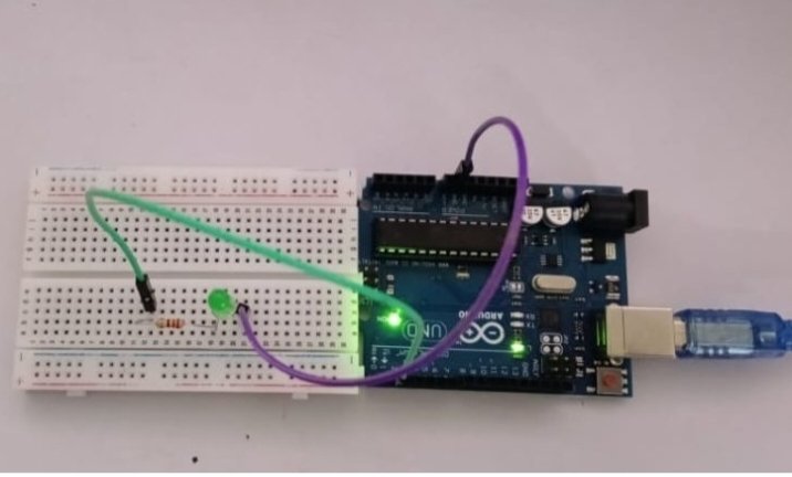
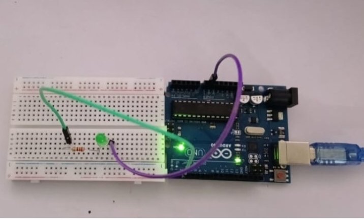
I connected the Led and Resistor to the Breadboard using Jumperwires and Connected it to Ardunio UNO board. Then connected the board to the CPU and through Ardunio IDE uploaded it.
// Simple LED Blinking Program

void setup() {
  pinMode(LED_BUILTIN, OUTPUT);   // Set the built-in LED as output
}

void loop() {
  digitalWrite(LED_BUILTIN, HIGH); // Turn LED ON
  delay(1000);                     // Wait for 1 second

  digitalWrite(LED_BUILTIN, LOW);  // Turn LED OFF
  delay(1000);                     // Wait for 1 second
}
Ardunio UNO Data Sheet
| Parameter | Specification |
|---|---|
| Board Name | Arduino Uno R3 |
| Microcontroller | ATmega328P |
| Operating Voltage | 5 V |
| Recommended Input Voltage | 7–12 V |
| Input Voltage Limits | 6–20 V |
| Digital I/O Pins | 14 |
| PWM Digital Pins | 6 (Pins 3, 5, 6, 9, 10, 11) |
| Analog Input Pins | 6 (A0–A5) |
| DC Current per I/O Pin | 20 mA |
| DC Current for 3.3 V Pin | 50 mA |
| Flash Memory | 32 KB (0.5 KB used by bootloader) |
| SRAM | 2 KB |
| EEPROM | 1 KB |
| Clock Speed | 16 MHz |
| USB Interface | USB Type-B |
| Communication Protocols | UART, I²C, SPI |
| Power Supply | USB, DC Barrel Jack, VIN Pin |
| Length | 68.6 mm |
| Width | 53.4 mm |
| Weight | Approximately 25 g |
Binary Number System
A binary number system is a number system that uses only two digits, 0 and 1, to represent all numbers. It is called binary because it is based on 2 and is widely used in computers and digital devices.
Binary Address
A binary address is a memory address written in the binary number system using only the digits 0 and 1. It is used by computers to identify the exact location of data or instructions stored in memory. Each memory location has a unique binary address, allowing the processor to quickly find, read, or write information.
Since computers operate internally using binary signals, memory addresses are naturally represented in binary form for efficient processing.
CODE:-
const byte ledPin = 0b00000010;  // Binary for decimal 2 (D2)

void setup() {
  pinMode(ledPin, OUTPUT);
}

void loop() {
  digitalWrite(ledPin, 0b1);  // ON
  delay(1000);
  digitalWrite(ledPin, 0b0);  // OFF
  delay(1000);
}
The program code written using binary numbers is shown above.
Hexadecimal Number System
A hexadecimal number system is a number system with base 16. It uses 16 symbols to represent numbers: 0–9 and A–F, where A = 10, B = 11, C = 12, D = 13, E = 14, and F = 15. Hexadecimal is widely used in computers because it provides a shorter and easier way to represent binary numbers. One hexadecimal digit is equivalent to 4 binary bits, making it convenient for programming, memory addresses, and digital systems.
Hexadecimal Number System
A hexadecimal address is a memory location represented using the base-16 number system, which uses the digits 0–9 and the letters A–F. It is commonly used in computers because it is shorter and easier to read than binary numbers. Programmers use hexadecimal addresses to identify memory locations, debug programs, and work with computer hardware
CODE:-
const byte ledPin = 0x02;  // Hexadecimal for D2

void setup() {
  pinMode(ledPin, OUTPUT);
}

void loop() {
  digitalWrite(ledPin, 0x1);  // HIGH (ON)
  delay(1000);

  digitalWrite(ledPin, 0x0);  // LOW (OFF)
  delay(1000);
}
The program code written in hexadecimal is shown above
2. ESP-32

ESP32 is a small and powerful microcontroller used to control electronic devices and IoT (Internet of Things) projects. It has built-in Wi-Fi and Bluetooth, so it can connect to the internet and communicate with other devices. It is commonly used in smart home systems, robots, sensors, and automation projects.
ESP-32 WROOM-32 Data Sheet
| Parameter | Specification |
|---|---|
| Manufacturer | Espressif Systems |
| Module Name | ESP32-WROOM-32 |
| Microcontroller | ESP32 |
| Processor | Dual-core 32-bit Xtensa® LX6 |
| Clock Speed | Up to 240 MHz |
| Operating Voltage | 3.0 V – 3.6 V (3.3 V typical) |
| Flash Memory | 4 MB SPI Flash (typical) |
| SRAM | 520 KB |
| ROM | 448 KB |
| Wi-Fi | IEEE 802.11 b/g/n (2.4 GHz) |
| Bluetooth | Bluetooth v4.2 BR/EDR + BLE |
| GPIO Pins | Up to 32 GPIO pins |
| ADC | 18-channel, 12-bit ADC |
| DAC | 2-channel, 8-bit DAC |
| PWM | Supported on most GPIO pins |
| Communication Interfaces | UART, SPI, I²C, I²S, CAN (TWAI), SD/SDIO |
| USB Interface | External USB-to-Serial converter required |
| Operating Temperature | -40°C to +85°C |
| Power Modes | Active, Light Sleep, Deep Sleep |
| Programming Support | Arduino IDE, ESP-IDF, PlatformIO, MicroPython |
| Typical Applications | IoT, Smart Home, Robotics, Automation, Wearable Devices, Wireless Sensor Networks |
| Package Size | 18 mm × 25.5 mm × 3.1 mm |
| Antenna | Built-in PCB Antenna |
| Security Features | Secure Boot, Flash Encryption, Cryptographic Hardware Acceleration |
Thonny
Thonny is a simple and easy-to-use Python Integrated Development Environment (IDE) designed especially for beginners. It allows users to write, run, and debug Python programs easily. Thonny is also used for programming microcontrollers such as the Raspberry Pi Pico, making it a popular tool for learning Python and embedded systems.
Installation of Thonny
Step 1

Step 2

Step 3

Step 4

Step 5

Step 6

Step 7

Step 8

External and Onboard LED woring with ESP-3
On board

I used the simple LED blinking program shown above. After writing the code in Thonny IDE, I clicked the Run button to upload and run the program on the ESP32 board. The onboard LED started blinking, which showed that the program was uploaded successfully and was working correctly.
ESP-32 External LED Blinking

The external LED is connected to GPIO13 and GND of the ESP32 using jumper wires on a breadboard. When the program runs, the ESP32 sends a signal through GPIO13, causing the LED to blink.
Code used for the blinking

from machine import Pin
from time import sleep

led = Pin(13, Pin.OUT)

while True:
    led.on()      # LED ON
    sleep(1)

    led.off()     # LED OFF
    sleep(1)
3. XIAO RP2040

The Seeed Studio XIAO RP2040 is a small and powerful microcontroller board based on the Raspberry Pi RP2040 chip. It is used for embedded systems, robotics, IoT, and electronics projects. The board has a dual-core ARM Cortex-M0+ processor running at 133 MHz, along with 2 MB of flash memory and 264 KB of SRAM. It supports programming with Arduino IDE, MicroPython, and CircuitPython, making it suitable for both beginners and advanced users. Its compact size and multiple GPIO pins make it easy to connect sensors, LEDs, and other electronic components.
Data sheet of XIAO RP2040
| Parameter | Specification |
|---|---|
| Manufacturer | Seeed Studio |
| Board Name | XIAO RP2040 |
| Microcontroller | Raspberry Pi RP2040 |
| Processor | Dual-core ARM Cortex-M0+ |
| Clock Speed | Up to 133 MHz |
| Flash Memory | 2 MB |
| SRAM | 264 KB |
| Operating Voltage | 3.3 V |
| Input Voltage | 5 V via USB Type-C |
| GPIO Pins | 11 GPIO Pins |
| Analog Inputs (ADC) | 4 Channels (12-bit ADC) |
| PWM | Supported on all GPIO pins |
| Communication Interfaces | UART, I²C, SPI |
| USB Interface | USB Type-C |
| On-board RGB LED | Yes (WS2812 RGB LED) |
| User LED | Yes |
| Reset Button | Yes |
| Boot Button | Yes |
| Programming Support | Arduino IDE, MicroPython, CircuitPython |
| Operating Temperature | -20°C to +70°C (Typical) |
| Board Size | 20 mm × 17.5 mm |
| Applications | Embedded Systems, IoT, Robotics, Wearable Devices, Automation, DIY Electronics |
On Board LED Blinking

I connected the cable to CPU and XIAO RP2040 to Breadboard


Code used for the Blinking
#include <Adafruit_NeoPixel.h>

#define LED_POWER 11      // Enable power to the RGB LED
#define LED_PIN   12      // Data pin for the WS2812 RGB LED
#define NUMPIXELS 1

Adafruit_NeoPixel rgb(NUMPIXELS, LED_PIN, NEO_GRB + NEO_KHZ800);

void setup() {
  pinMode(LED_POWER, OUTPUT);
  digitalWrite(LED_POWER, HIGH);   // Turn ON power to RGB LED

  rgb.begin();
  rgb.clear();
  rgb.show();

  Serial.begin(115200);

  while (!Serial);

  Serial.println("===== XIAO RP2040 RGB Control =====");
  Serial.println("Commands:");
  Serial.println("red");
  Serial.println("green");
  Serial.println("blue");
  Serial.println("yellow");
  Serial.println("cyan");
  Serial.println("purple");
  Serial.println("white");
  Serial.println("off");
}

void loop() {

  if (Serial.available()) {

    String cmd = Serial.readStringUntil('\n');
    cmd.trim();

    if (cmd == "red")
      rgb.setPixelColor(0, rgb.Color(255, 0, 0));

    else if (cmd == "green")
      rgb.setPixelColor(0, rgb.Color(0, 255, 0));

    else if (cmd == "blue")
      rgb.setPixelColor(0, rgb.Color(0, 0, 255));

    else if (cmd == "yellow")
      rgb.setPixelColor(0, rgb.Color(255, 255, 0));

    else if (cmd == "cyan")
      rgb.setPixelColor(0, rgb.Color(0, 255, 255));

    else if (cmd == "purple")
      rgb.setPixelColor(0, rgb.Color(255, 0, 255));

    else if (cmd == "white")
      rgb.setPixelColor(0, rgb.Color(255, 255, 255));

    else if (cmd == "off")
      rgb.setPixelColor(0, rgb.Color(0, 0, 0));

    rgb.show();
  }
}
4. XIAO ESP32C3

The Seeed Studio XIAO ESP32-C3 is a compact and powerful microcontroller board based on the ESP32-C3 chip from Espressif. It is designed for IoT, embedded systems, robotics, and smart electronics projects. The board has a 32-bit RISC-V processor running at 160 MHz, along with built-in Wi-Fi and Bluetooth Low Energy (BLE) for wireless communication. It supports programming using the Arduino IDE, MicroPython, and ESP-IDF, making it suitable for both beginners and advanced users. Its small size, low power consumption, and built-in wireless connectivity make it ideal for portable and connected devices.
Data sheet of XIAO ESP32C3
| Parameter | Specification |
|---|---|
| Manufacturer | Seeed Studio |
| Board Name | XIAO ESP32-C3 |
| Microcontroller | ESP32-C3 |
| Processor | Single-core 32-bit RISC-V |
| Clock Speed | Up to 160 MHz |
| Flash Memory | 4 MB |
| SRAM | 400 KB |
| Operating Voltage | 3.3 V |
| Input Voltage | 5 V via USB Type-C |
| GPIO Pins | 11 GPIO Pins |
| Analog Inputs (ADC) | 4 Channels (12-bit ADC) |
| PWM | Supported |
| Communication Interfaces | UART, I²C, SPI |
| Wi-Fi | IEEE 802.11 b/g/n (2.4 GHz) |
| Bluetooth | Bluetooth 5.0 Low Energy (BLE) |
| USB Interface | USB Type-C |
| On-board RGB LED | Yes (WS2812 RGB LED) |
| Reset Button | Yes |
| Boot Button | Yes |
| Programming Support | Arduino IDE, ESP-IDF, MicroPython |
| Operating Temperature | -40°C to +85°C |
| Board Size | 20 mm × 17.5 mm |
| Applications | IoT, Smart Home, Robotics, Automation, Wearable Devices, Wireless Sensor Networks |
LED blinking

Code used
const int LED_PIN = 1;   // GPIO1

void setup() {
  pinMode(LED_PIN, OUTPUT);
}

void loop() {
  digitalWrite(LED_PIN, HIGH);  // Turn LED ON
  delay(1000);                  // Wait for 1 second

  digitalWrite(LED_PIN, LOW);   // Turn LED OFF
  delay(1000);                  // Wait for 1 second
}