Introduction
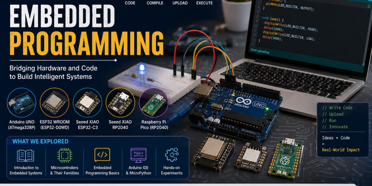
This week, I explored embedded programming by working with different microcontrollers and completing both group and individual assignments. During the group assignment, we studied and compared the toolchains, architectures, and development workflows of various embedded platforms. This helped me understand their features, differences, and practical applications.
For the individual assignment, I installed the Thonny IDE and configured it for MicroPython development. I studied the microcontroller datasheet, wrote and uploaded MicroPython programs, and tested them on the microcontroller. I also developed programs to control input and output devices and established communication through wired interfaces. This hands-on experience improved my understanding of embedded systems, MicroPython programming, hardware interfacing, and the overall embedded software development process.
Group assignment
Introduction
As part of our group assignment, we studied and compared different microcontroller and IoT development platforms by analyzing their architectures, toolchains, and development workflows. The objective of this comparison was to understand how different microcontrollers are designed, how software is developed and uploaded to them, and how they can be integrated with sensors and communication technologies for embedded system applications.
During this study, we explored the differences between popular Microcontrollers such as Arduino uno, ESP32, XIAO ESP32-C3, Raspberry Pi Pico, and XIAO RP2040. We compared their processor architectures, programming environments, supported programming languages, development tools, debugging methods, and programming workflows. We also studied how these boards interface with different sensors and peripherals for real-world IoT applications. This comparison helped us understand the strengths, limitations, and practical use cases of each platform, making it easier to select the most suitable microcontroller for different embedded and IoT projects.


Comparison of Microcontroller Architectures
Detailed Comparison of Microcontroller Architectures
| Parameters | Arduino Uno | ESP32-WROOM | ESP32-C3 | Raspberry Pi Pico | XIAO RP2040 |
|---|---|---|---|---|---|
| Microcontroller | ATmega328P | ESP32 | ESP32-C3 | RP2040 | RP2040 |
| Processor Core | Single Core | Dual Core | Single Core | Dual Core | Dual Core |
| Architecture | 8-bit AVR RISC | 32-bit Xtensa LX6 | 32-bit RISC-V | 32-bit ARM Cortex-M0+ | 32-bit ARM Cortex-M0+ |
| Clock Speed | 16 MHz | Up to 240 MHz | Up to 160 MHz | Up to 133 MHz | Up to 133 MHz |
| Operating Voltage | 5V | 3.3V | 3.3V | 3.3V | 3.3V |
| GPIO Voltage | 5V | 3.3V | 3.3V | 3.3V | 3.3V |
| Digital GPIO Pins | 14 | Up to 34 | Up to 22 | 26 | Up to 11 |
| PWM Pins | 6 | Up to 16 | Up to 6 | 16 | Up to 11 |
| Analog Input Pins (ADC) | 6 | Up to 18 | Up to 6 | 3 | Up to 4 |
| DAC | No | 2 | No | No | No |
| Communication Interfaces | UART, SPI, I2C | UART, SPI, I2C, I2S | UART, SPI, I2C | UART, SPI, I2C | UART, SPI, I2C |
| Wi-Fi | No | Yes (2.4 GHz) | Yes (2.4 GHz) | No | No |
| Bluetooth | No | Bluetooth Classic + BLE | BLE 5.0 | No | No |
| USB Interface | USB Type-B | Micro-USB | USB Type-C | Micro-USB | USB Type-C |
| Programming Language | C/C++ | C/C++, MicroPython | C/C++, MicroPython | C/C++, MicroPython | C/C++, MicroPython |
| On-board LED Pin | D13 | GPIO2 | GPIO8 | GPIO25 | GPIO25 |
| Flash Memory | 32 KB | 4 MB | 4 MB | 2 MB | 2 MB |
| RAM (SRAM) | 2 KB | 520 KB | 400 KB | 264 KB | 264 KB |
| EEPROM | 1 KB | Emulated in Flash | Emulated in Flash | Emulated in Flash | Emulated in Flash |
| CPU Bit Width | 8-bit | 32-bit | 32-bit | 32-bit | 32-bit |
| Power Consumption | Low | Medium–High | Low | Low | Low |
| Debugging Support | Serial Monitor | Serial, JTAG | Serial, JTAG | Serial, SWD | Serial, SWD |
| Built-in Wi-Fi Antenna | No | Yes | Yes | No | No |
| Built-in RGB LED | No | No (depends on board) | Depends on board | No | Yes |
| Suitable Applications | Basic embedded systems, education | IoT, Smart Home, Wireless Applications | Low-power IoT, Wearables | Robotics, Automation, Embedded Systems | Wearables, Robotics, Real-time Embedded Systems |
| Advantages | Easy to learn, large community support | High performance, Wi-Fi & Bluetooth, multicore | Low power, RISC-V, Wi-Fi & BLE | Powerful dual-core MCU, low cost, flexible I/O | Compact size, dual-core performance, reliable real-time control |
| Limitations | Limited memory and processing power | Higher power consumption | Fewer GPIOs than ESP32 | No built-in Wi-Fi or Bluetooth | No built-in Wi-Fi or Bluetooth |
Development Workflow Comparison
In this group assignment, we compared the development workflows of Arduino Uno, ESP32-WROOM, XIAO ESP32-C3, Raspberry Pi Pico, and XIAO RP2040. We used Arduino IDE and Thonny IDE to write, upload, and test programs on these microcontroller platforms. This comparison helped us understand the programming process, software setup, code uploading methods, and overall development workflow of each board. By working with different platforms, we learned how each microcontroller is programmed and how the development process varies depending on the hardware and software used.
| Parameter | Arduino Uno | ESP32-WROOM | ESP32-C3 | Raspberry Pi Pico | XIAO RP2040 |
|---|
| Primary IDE | Arduino IDE | Arduino IDE, ESP-IDF, PlatformIO | Arduino IDE, ESP-IDF, PlatformIO | Arduino IDE, Thonny, Pico SDK, PlatformIO | Arduino IDE, Thonny, PlatformIO |
| Programming Languages | C/C++ | C/C++, MicroPython | C/C++, MicroPython | C/C++, MicroPython | C/C++, MicroPython |
| Compiler | AVR-GCC | Xtensa GCC | RISC-V GCC | ARM GCC | ARM GCC |
| SDK/Framework | Arduino Core | ESP-IDF, Arduino Core | ESP-IDF, Arduino Core | Pico SDK, Arduino Core | Arduino Core, Pico SDK |
| Code Upload Method | USB Bootloader | USB/UART | USB/UART | USB Mass Storage (UF2) / SWD | USB Drag & Drop (UF2) / SWD |
| Driver Requirement | Usually No | USB Driver may be required | USB Driver may be required | No | No |
| Debugging Support | Serial Monitor | Serial Monitor, JTAG | Serial Monitor, JTAG | Serial Monitor, SWD | Serial Monitor, SWD |
| Serial Communication | USB Serial | USB/UART Serial | USB/UART Serial | USB Serial | USB Serial |
| Library Support | Extensive Arduino Libraries | Arduino + ESP-IDF Libraries | Arduino + ESP-IDF Libraries | Arduino & Pico SDK Libraries | Arduino & Pico SDK Libraries |
| Wireless Development | Not Supported | Wi-Fi & Bluetooth | Wi-Fi & BLE | Not Supported | Not Supported |
| Firmware Update | USB Upload | USB/UART OTA (Wi-Fi) | USB/UART OTA (Wi-Fi) | USB UF2 | USB UF2 |
| Operating Systems Supported | Windows, Linux, macOS | Windows, Linux, macOS | Windows, Linux, macOS | Windows, Linux, macOS | Windows, Linux, macOS |
| Learning Difficulty | Very Easy | Intermediate | Intermediate | Beginner to Intermediate | Beginner |
| Development Speed | Fast | Fast | Fast | Fast | Fast |
| Best Use Case | Learning Embedded Systems | IoT and Smart Devices | Low-Power IoT Applications | Robotics and Embedded Systems | Compact Embedded and Wearable Projects |

Development Workflow (Arduino IDE)
The Arduino IDE provides a simple and user-friendly environment for developing embedded applications. The typical development workflow consists of the following steps:
- Install Arduino IDE and the required board support package.
- Connect the microcontroller board (Arduino Uno, ESP32-WROOM, ESP32-C3, Raspberry Pi Pico, or XIAO RP2040) to the computer using a USB cable.
- Select the correct Board and COM Port from the Tools menu.
- Write or open the program (sketch) in the Arduino IDE.
- Verify (Compile) the code to check for syntax and compilation errors.
- Upload the compiled program to the microcontroller.
- Open the Serial Monitor or Serial Plotter to observe program output and debug the application.
- Test the hardware and modify the code if required.
- Repeat the compile–upload–test cycle until the desired functionality is achieved.
Development Workflow:
Write Code → Verify (Compile) → Upload → Run on Microcontroller → Debug using Serial Monitor → Test & Improve
Development Workflow (MicroPython)
MicroPython provides a simple and interactive way to program supported microcontrollers such as ESP32-WROOM, XIAO ESP32-C3, Raspberry Pi Pico, and XIAO RP2040. The development workflow using Thonny IDE consists of the following steps:
- Install Thonny IDE on your computer.
- Install the MicroPython firmware on the microcontroller (if it is not already installed).
- Connect the microcontroller to the computer using a USB cable.
- Select the correct interpreter and COM port in Thonny IDE.
- Write or open the MicroPython program (
.pyfile). - Run the program directly from Thonny or save it to the board as
main.pyorboot.py. - View the Shell (REPL) to monitor program output, debug errors, and interact with the board.
- Test the hardware, modify the code if needed, and run it again.
- Repeat the edit–run–test cycle until the application works as expected.
Development Workflow:
Write Code → Run/Save to Board → Execute on Microcontroller → Debug using REPL (Shell) → Test & Improve
Comparison Summary
The comparison of Arduino Uno, ESP32-WROOM, XIAO ESP32-C3, Raspberry Pi Pico, and XIAO RP2040 highlighted the differences in their architectures, toolchains, and development workflows.
- Arduino Uno is the best choice for beginners due to its simple hardware, easy programming, and extensive community support.
- ESP32-WROOM offers the highest performance with dual-core processing, built-in Wi-Fi, and Bluetooth, making it ideal for IoT and wireless applications.
- XIAO ESP32-C3 is a compact and power-efficient board based on the RISC-V architecture. It supports Wi-Fi and BLE, making it suitable for low-power IoT and wearable devices.
- Raspberry Pi Pico features the RP2040 dual-core ARM Cortex-M0+ processor, providing excellent performance for robotics, automation, and embedded control applications.
- XIAO RP2040 uses the same RP2040 processor in a smaller form factor, making it ideal for compact embedded systems and wearable projects.
From the toolchain comparison, Arduino IDE provides the easiest development experience for C/C++ programming across all boards, while Thonny IDE simplifies MicroPython development for supported boards. Boards based on ESP32 and RP2040 offer more advanced features, faster processing, and better flexibility than the Arduino Uno, making them suitable for modern embedded and IoT applications.
Embedded Programming
Embedded programming is the process of writing software for small computers built into electronic devices. These computers are known as embedded systems, and they are designed to perform specific tasks efficiently and reliably rather than serving as general-purpose computers. The software runs directly on a microcontroller or processor, enabling the device to interact with hardware components such as LEDs, sensors, motors, displays, and communication modules.
Embedded programming is widely used in everyday products, including home appliances, smartwatches, medical devices, industrial automation systems, automotive electronics, robotics, and IoT (Internet of Things) devices. The programs are typically written in languages such as C/C++ or MicroPython using development environments like Arduino IDE and Thonny IDE.
In this assignment, embedded programming was used to develop and test applications on Arduino Uno, ESP32-WROOM, XIAO ESP32-C3, Raspberry Pi Pico, and XIAO RP2040. We learned how to write code, compile it, upload it to the microcontroller, and verify its operation by controlling hardware and communicating with peripherals. This hands-on experience provided a better understanding of embedded software development and the interaction between hardware and software.
Embedded Systems
An embedded system is a specialized computer system designed to perform a specific function within a larger electronic device. Unlike a general-purpose computer, an embedded system is dedicated to a particular task and is optimized for efficiency, reliability, and low power consumption. It consists of both hardware (such as a microcontroller, sensors, memory, and communication interfaces) and software (embedded programs) that work together to control the device.
Embedded systems are widely used in everyday life, including home appliances, automobiles, medical equipment, industrial automation, consumer electronics, robotics, and Internet of Things (IoT) devices. They monitor inputs from sensors, process data, and control outputs such as LEDs, motors, displays, and communication modules.
In this assignment, we worked with embedded system development boards including Arduino Uno, ESP32-WROOM, XIAO ESP32-C3, Raspberry Pi Pico, and XIAO RP2040. By programming these boards using Arduino IDE and Thonny IDE, we gained practical experience in developing embedded applications and understanding how hardware and software interact to perform specific tasks.


What is a Microcontroller?
A microcontroller (MCU) is a compact integrated circuit that contains a processor (CPU), memory (Flash and RAM), and input/output (I/O) peripherals on a single chip. It is designed to perform specific tasks by executing a program stored in its memory. Microcontrollers are the core components of embedded systems and are widely used to control electronic devices.
A microcontroller can receive input from sensors, process the data according to the programmed instructions, and control output devices such as LEDs, motors, displays, and communication modules. It is commonly programmed using languages such as C/C++ and MicroPython through development environments like Arduino IDE and Thonny IDE.
Microcontrollers are widely used in home appliances, automobiles, industrial automation, robotics, medical devices, consumer electronics, and Internet of Things (IoT) applications because they are compact, cost-effective, reliable, and consume very little power.
What is a Microprocessor?
A microprocessor (MPU) is a programmable integrated circuit that acts as the central processing unit (CPU) of a computer or electronic system. It is designed to execute instructions, perform calculations, process data, and control the overall operation of a system. Unlike a microcontroller, a microprocessor mainly contains only the CPU and requires external memory (RAM and ROM/Flash) and input/output (I/O) devices to function.
Microprocessors are capable of handling complex tasks and running full operating systems such as Windows, Linux, and Android. They are commonly used in desktop computers, laptops, smartphones, tablets, servers, and advanced embedded systems where high processing power and multitasking are required.
Microprocessors are ideal for applications that need high-speed computation, advanced graphics, networking, and the ability to run multiple programs simultaneously.
Difference Between Microcontroller and Microprocessor
| Microcontroller | Microprocessor |
|---|---|
| A microcontroller integrates the CPU, RAM, Flash memory, and input/output (I/O) peripherals on a single chip. | A microprocessor mainly contains only the CPU and requires external RAM, ROM/Flash, and I/O devices to operate. |
| It is designed for specific or dedicated tasks in embedded systems. | It is designed for general-purpose computing and can perform a wide variety of tasks. |
| It consumes less power, making it ideal for battery-powered and portable devices. | It consumes more power due to its higher processing capability and external components. |
| It is cost-effective because most required components are integrated into one chip. | It is generally more expensive since it requires additional external hardware. |
| It offers moderate processing speed, which is sufficient for controlling sensors, motors, displays, and other peripherals. | It provides high processing speed and is capable of handling complex computations and multitasking. |
| It has built-in RAM and Flash/ROM memory. | It requires external RAM, ROM/Flash, and storage. |
| It is commonly programmed using C/C++ or MicroPython for embedded applications. | It is commonly used with operating systems such as Windows, Linux, or Android and supports many programming languages. |
| It is widely used in embedded systems, home appliances, IoT devices, robotics, automotive electronics, and industrial automation. | It is widely used in desktop computers, laptops, smartphones, tablets, servers, and workstations. |
| Examples include ATmega328P, ESP32, ESP32-C3, and RP2040. | Examples include Intel Core i5/i7, AMD Ryzen, ARM Cortex-A series, and Qualcomm Snapdragon processors. |
| Advantages: Low power consumption, compact size, low cost, and easy hardware interfacing. | Advantages: High performance, multitasking capability, and support for complex operating systems and applications. |
Binary Number System
A binary number system is a number system that uses only two digits: 0 and 1. It is the fundamental language of computers because electronic circuits can easily represent two states: OFF (0) and ON (1).
Why is Binary Used?
Computers understand only two electrical states:
0 = OFF (Low Voltage)
1 = ON (High Voltage)
This makes binary reliable and easy for digital devices to process.
Examples
Applications of Binary
Computers and laptops
Microcontrollers (Arduino, ESP32, RP2040)
Mobile phones
Digital electronics
Memory and data storage
Communication systems
Binary is the language of computers. Every letter, number, image, sound, and video inside a computer is ultimately stored and processed as a combination of 0s and 1s.
Hexadecimal Number System
A hexadecimal number system is a base-16 number system that uses 16 symbols:
0, 1, 2, 3, 4, 5, 6, 7, 8, 9, A, B, C, D, E, F
Where:
A = 10
B = 11
C = 12
D = 13
E = 14
F = 15
Why is Hexadecimal Used?
It represents large binary numbers in a short and easy-to-read format.
1 hexadecimal digit = 4 binary bits (1 nibble).
It is widely used in programming, microcontrollers, memory addresses, and color codes.
Applications
Memory addresses in computers
Microcontrollers (Arduino, ESP32, RP2040)
Programming and debugging
HTML/CSS color codes (e.g., #FF0000 = Red)
Embedded systems and digital electronics
Hexadecimal is a compact way to write binary numbers. Instead of writing long strings of 0s and 1s, we use the digits 0–9 and letters A–F, making the numbers easier to read and work with.
Individual assignment
Microcontrollers and their Datasheets overview
1.Arduino UNO

The Arduino Uno is one of the most popular and beginner-friendly microcontroller development boards. It is based on the ATmega328P microcontroller from Microchip and is widely used for learning embedded systems, electronics, robotics, and prototyping. The board provides a simple programming environment through the Arduino IDE and supports a large collection of libraries, making it easy to interface with sensors, actuators, and communication module
Microcontroller: ATmega328P
Architecture: 8-bit AVR RISC
Processor: Single-Core
Clock Speed: 16 MHz
Operating Voltage: 5V
Recommended Input Voltage: 7–12V
Input Voltage Limits: 6–20V
Flash Memory: 32 KB (0.5 KB used by the bootloader)
SRAM: 2 KB
EEPROM: 1 KB
Digital I/O Pins: 14 (Pins 0–13)
PWM Output Pins: 6 (Pins 3, 5, 6, 9, 10, 11)
Analog Input Pins: 6 (A0–A5) with 10-bit ADC resolution
Communication Interfaces: UART, SPI, I2C (TWI)
USB Interface: USB Type-B
Built-in LED: Digital Pin 13 (D13)
DC Current per I/O Pin: 20 mA (recommended)
DC Current for 3.3V Pin: 50 mA
Programming Language: C/C++
Development Environment: Arduino IDE
Power Supply Options: USB cable or external DC power adapter
Applications: Embedded systems, robotics, sensor interfacing, home automation, IoT prototyping, educational projects
Embedded programming with Arduino and installation

First, I searched for the Arduino IDE for Windows and downloaded it.

I installed the Arduino UNO version. |

After installing, I opened the software and selected the Arduino Uno as the board and chose the correct port to connect my Arduino. Then I went to the Examples section and opened the built-in LED blink program.

After uploading, the LED started blinking, which confirmed that the Arduino board was connected correctly and working successfully.

void loop()
digitalWrite(LED_BUILTIN, HIGH); // change state of the LED by setting the pin to the HIGH voltage level
delay(1000); // wait for a second
digitalWrite(LED_BUILTIN, LOW); // change state of the LED by setting the pin to the LOW voltage level
delay(1000); // wait for a second
}
I uploaded this program to the Arduino to test if the board was working properly.
2.XIAO RP2040
The Seeed Studio XIAO RP2040 is a compact and powerful microcontroller development board based on the Raspberry Pi RP2040 microcontroller. It features a dual-core ARM Cortex-M0+ processor, making it suitable for embedded systems, robotics, IoT, wearable devices, and rapid prototyping. Despite its small size, it provides multiple GPIO pins, analog inputs, PWM outputs, and communication interfaces such as UART, SPI, and I2C. The board also includes an onboard RGB NeoPixel LED, which can be programmed to display different colors.

XIAO RP2040 Datasheet
- Microcontroller: Raspberry Pi RP2040
- Architecture: 32-bit ARM Cortex-M0+
- Processor: Dual-Core
- Clock Speed: Up to 133 MHz
- Operating Voltage: 3.3V
- Input Voltage: 5V via USB Type-C or 3.3V via 3V3 pin
- Flash Memory: 2 MB
- SRAM: 264 KB
- EEPROM: Not available (can be emulated in Flash memory)
- Digital I/O Pins: 11 GPIO Pins
- PWM Output Pins: Available on all GPIO pins
- Analog Input Pins: 4 (12-bit ADC)
- Communication Interfaces: UART, SPI, I²C, USB
- USB Interface: USB Type-C
- Built-in LED: RGB NeoPixel (WS2812) and Power LED
- DC Current per I/O Pin: Up to 12 mA (recommended)
- Programming Languages: C/C++, MicroPython, CircuitPython
- Development Environment: Arduino IDE, Thonny IDE, PlatformIO
- Power Supply Options: USB Type-C or regulated 3.3V supply
- Applications: Embedded systems, IoT devices, robotics, wearable electronics, sensor interfacing, automation projects, rapid prototyping, and educational applications.
For the individual assignment, I worked with the Seeed Studio XIAO RP2040 microcontroller and learned how to control its onboard RGB NeoPixel LED using the Arduino IDE Serial Monitor. First, I installed the required board package and NeoPixel library, then connected the board to my computer using a USB Type-C cable.
I wrote an Arduino program that continuously reads commands from the Serial Monitor. By typing color names such as RED, GREEN, BLUE, or OFF, the program changes the color of the onboard RGB LED accordingly. The Serial Monitor also displays messages confirming the selected color, making it easy to verify that the commands are being received and executed correctly.
This activity helped me understand serial communication, user input processing, and RGB LED control on the XIAO RP2040. It also provided practical experience with programming an embedded system, uploading code, and testing hardware functionality through the Serial Monitor.
code
#include <Adafruit_NeoPixel.h>
#define LED_POWER 11 // Enable power to the RGB LED
#define LED_PIN 12 // Data pin for the WS2812 RGB LED
#define NUMPIXELS 1
Adafruit_NeoPixel pixels(NUMPIXELS, PIN_NEOPIXEL, NEO_GRB + NEO_KHZ800);
void setup() {
pinMode(LED_POWER, OUTPUT);
digitalWrite(LED_POWER, HIGH); // TurnON power to RGB LED
rgb.begin();
rgb.clear();
rgb.show();
Serial.begin(115200);
while (!Serial);
Serial.println(“====== XIAO RP2040 RGB Control =====”);
Serial.println(“Commands:”);
Serial.println(“red”);
Serial.println(“green”);
Serial.println(“blue”);
Serial.println(“Off”);
}
void loop() {
if (Serial.available()) {
char c = toupper(Serial.read());
switch (c) {
case ‘R’:
pixels.setPixelColor(0, pixels.Color(255, 0, 0));
break;
case ‘G’:
pixels.setPixelColor(0, pixels.Color(0, 255, 0));
break;
case ‘B’:
pixels.setPixelColor(0, pixels.Color(0, 0, 255));
break;
case ‘O’:
pixels.clear();
break;
}
pixels.show();
}
}

3.ESP-WROOM32
For this assignment, I explored MicroPython programming on the ESP32 using the Thonny IDE. MicroPython is a lightweight implementation of Python designed for microcontrollers, making it easy to develop and test embedded applications.
First, I installed Thonny IDE and configured it for the ESP32. After connecting the ESP32 board to my computer through a USB cable, I installed the MicroPython firmware and selected the correct interpreter and COM port in Thonny. Once the setup was complete, I wrote and executed MicroPython programs directly from the IDE.
As part of the practical activity, I created programs to control the ESP32’s GPIO pins, such as blinking an LED and reading serial output through the Thonny Shell. I also learned how to upload, edit, and run Python scripts stored on the ESP32.

ESP32 Datasheet
- Microcontroller: ESP32
- Architecture: 32-bit Xtensa® LX6
- Processor: Dual-Core
- Clock Speed: Up to 240 MHz
- Operating Voltage: 3.3V
- Input Voltage: 5V via USB or VIN pin
- Flash Memory: 4 MB (typical, varies by module)
- SRAM: 520 KB
- EEPROM: Not available (can be emulated in Flash memory)
- Digital I/O Pins: Up to 34 GPIO Pins (varies by board)
- PWM Output Pins: Available on most GPIO pins
- Analog Input Pins: Up to 18 (12-bit ADC)
- Communication Interfaces: UART, SPI, I²C, I²S, CAN, Wi-Fi, Bluetooth (Classic + BLE)
- USB Interface: USB (via USB-to-UART converter on most development boards)
- Built-in LED: Available on some ESP32 development boards (varies by board)
- DC Current per I/O Pin: Up to 40 mA (recommended lower for reliable operation)
- Programming Languages: C/C++, MicroPython
- Development Environment: Arduino IDE, ESP-IDF, Thonny IDE, PlatformIO
- Power Supply Options: USB, VIN pin (5V), or regulated 3.3V supply
- Applications: IoT devices, smart home automation, wireless sensor networks, robotics, industrial automation, wearable electronics, web servers, data logging, and embedded systems.
Installation of Thonny:-
Thonny IDE is a simple and beginner-friendly Integrated Development Environment (IDE) designed for Python and MicroPython programming. It is widely used for programming microcontrollers such as the ESP32, Raspberry Pi Pico, and XIAO RP2040. Thonny provides an easy-to-use interface for writing, running, debugging, and uploading MicroPython programs directly to supported boards.

Visit the official Thonny website.


Download the latest version of Thonny IDE for your operating system (Windows)

Run the downloaded installer.Click Finish to complete the setup.

Follow the installation wizard and click Next until the installation is complete.

Launch Thonny IDE from the Start Menu or Desktop shortcut.

In Thonny, go to Run → Select Interpreter.

Choose MicroPython (ESP32) for an ESP32 board or MicroPython (Raspberry Pi Pico) for an RP2040 board.


Select the correct COM Port and click OK.


If MicroPython firmware is not installed, click Install or Update MicroPython, select the firmware, and install it.

Write your MicroPython program in the editor.

Connect your microcontroller ESP32 to the computer using a USB cable.
from machine import Pin
from time import sleep
led = Pin(2, Pin.OUT) # GPIO2 (Built-in LED on many ESP32 boards)
while True:
led.on() # LED ON
sleep(0.5) # Delay 500 ms
led.off() # LED OFFsleep(0.5) # Delay 500 msClick the Run button (or press F5) to execute the program.

4.XIAO ESP32C3
The Seeed Studio XIAO ESP32-C3 is a compact and powerful microcontroller development board based on the ESP32-C3 microcontroller from Espressif Systems. It features a 32-bit RISC-V single-core processor running at up to 160 MHz, making it suitable for embedded systems, IoT devices, and wireless applications. The board includes built-in 2.4 GHz Wi-Fi and Bluetooth 5 (BLE), enabling seamless wireless communication.

XIAO ESP32-C3 Datasheet
- Microcontroller: ESP32-C3
- Architecture: 32-bit RISC-V
- Processor: Single-Core
- Clock Speed: Up to 160 MHz
- Operating Voltage: 3.3V
- Input Voltage: 5V via USB Type-C or 3.3V via the 3V3 pin
- Flash Memory: 4 MB
- SRAM: 400 KB
- EEPROM: Not available (can be emulated in Flash memory)
- Digital I/O Pins: 11 GPIO Pins
- PWM Output Pins: Available on all GPIO pins
- Analog Input Pins: 4 (12-bit ADC)
- Communication Interfaces: UART, SPI, I²C, USB, Wi-Fi (2.4 GHz), Bluetooth 5 Low Energy (BLE)
- USB Interface: USB Type-C
- Built-in LED: User LED and Power LED
- DC Current per I/O Pin: Up to 20 mA (recommended)
- Programming Languages: C/C++, MicroPython
- Development Environment: Arduino IDE, ESP-IDF, Thonny IDE, PlatformIO
- Power Supply Options: USB Type-C or regulated 3.3V supply
- Applications: IoT devices, wireless sensor networks, smart home automation, robotics, wearable electronics, industrial monitoring, embedded systems, and rapid prototyping.
LED Blinking using XIAO ESP32-C3
For this assignment, I used the Seeed Studio XIAO ESP32-C3 microcontroller to run a basic LED blinking experiment with the Arduino IDE. After installing the ESP32 board package, I connected the XIAO ESP32-C3 to my computer using a USB Type-C cable and chose the right board and COM port.
An external LED was connected to a GPIO pin using a current-limiting resistor. I created an Arduino program to turn the LED ON and OFF with a set delay. After uploading the program, the LED blinked continuously, showing that the GPIO pin was working correctly.
This experiment taught me how to connect an external LED to the XIAO ESP32-C3, set GPIO pins as digital outputs, upload programs with the Arduino IDE, and test the hardware. It also improved my grasp of basic embedded programming and digital output control.


5.Raspberry Pi Pico
Raspberry Pi Pico is a low-cost and powerful microcontroller development board developed by the Raspberry Pi Foundation. It is based on the RP2040 microcontroller and is designed for embedded systems, electronics, robotics, and IoT projects. It is easy to program and is suitable for both beginners and advanced users.

Features of Raspberry Pi Pico
Based on RP2040 microcontroller.
32-bit ARM Cortex-M0+ architecture.
Dual-core processor.
Up to 133 MHz clock speed.
3.3V operating voltage.
26 GPIO pins.
3 Analog (ADC) input pins.
16 PWM channels.
264 KB SRAM.
2 MB Flash memory.
Supports UART, SPI, and I2C communication.
Micro-USB interface.
Supports Arduino IDE, Thonny IDE (MicroPython), and C/C++ SDK.
Applications
Embedded systems
Robotics
Sensor interfacing
Home automation
IoT projects
Educational projects
Task:
Blink LED Using Raspberry Pi Pico
To learn the basic operation of the Raspberry Pi Pico by blinking its onboard LED using the Arduino IDE.
Components Used
Raspberry Pi Pico
USB Cable
Computer with Arduino IDE
Working
The program controls the onboard LED of the Raspberry Pi Pico. The LED turns ON for one second and then turns OFF for one second. This process repeats continuously, creating a blinking effect.
Arduino Code
void setup() {
pinMode(LED_BUILTIN, OUTPUT);
}
void loop() {
digitalWrite(LED_BUILTIN, HIGH);
delay(1000);
digitalWrite(LED_BUILTIN, LOW);
delay(1000);
}
Conclusion
This assignment taught me about embedded programming by looking at different microcontrollers, their designs, and how to program them. Working in a group, I compared platforms like Arduino Uno, ESP32-WROOM, XIAO ESP32-C3, Raspberry Pi Pico, and XIAO RP2040, which showed me their features, advantages, and best uses.
During the individual assignment, I gained practical experience by programming microcontrollers using Arduino IDE and Thonny IDE. I worked on LED control, serial communication, and MicroPython programming while learning to upload, test, and debug embedded applications. These activities enhanced my understanding of GPIO interfacing, hardware-software interaction, and embedded system development.
Overall, this assignment improved my understanding of embedded systems, microcontrollers, and IoT development. It also boosted my skills in programming, debugging, and hardware interfacing, laying a strong groundwork for future embedded and IoT projects.