INTRODUCTION
For generations, the creation of Shadu Mati Ganapati idols has been a process where natural clay is shaped through patient, manual effort. While this traditional craft remains vital, the existing methods of production are often slow and physically demanding for the people involved. This project is born from an exploration into how these manual processes can be better understood through a technical lens. By looking at the physical properties of the clay and the mechanics of the work, we are developing a new “Build Method” that introduces efficiency into the heart of this ancient tradition.
ABOUT SHADU GANAPATI
- Shadu mati
This is a type of natural, secondary clay, often sourced from riverbanks or specific earth deposits. It is entirely biodegradable and dissolves back into its original earth form when submerged in water. -
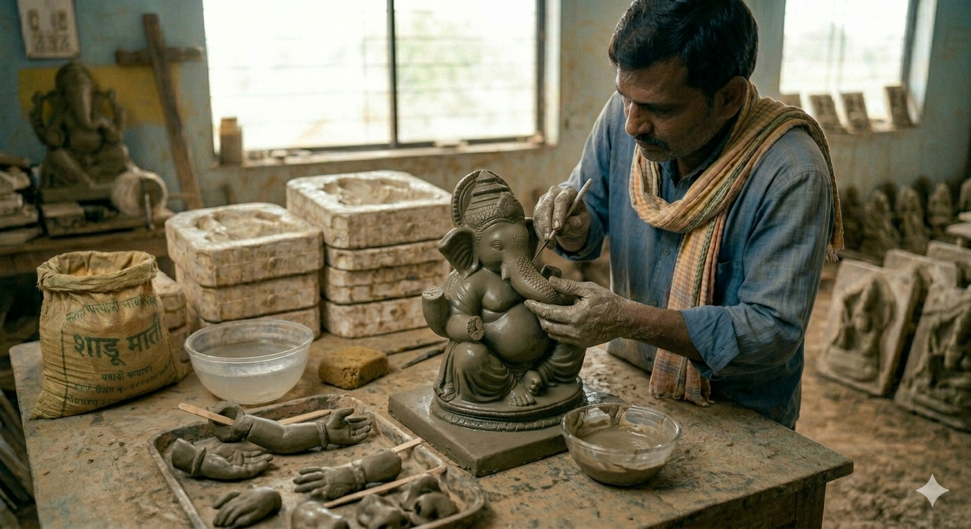
Shadu Mati Ganapati is a traditional Lord Ganesha idol made entirely from natural, eco-friendly river clay called shadu instead of artificial plaster.
People choose these idols because they keep the festival pure and gentle on nature. During the immersion ritual, the clay dissolves completely and safely back into the water within a few hours, leaving behind zero pollution and protecting marine life.

problem statement
Shadu mati ganapati or any eco friendly ganapati idol face common problem. A high manual work and labour cost.
this type of idol is not expencive because of material or quality, The only reason is it take time and effort in making this type of idol. Compare to POP (Plaster of Paris) idol which get ready in 10 min for one idol. Our eco friendly idols take 40 min to 1 hour(for 1 feet idol) to make. And time and effort increase based on size of idol.(This imformation is for base raw idol before coloring.)
so, Reducing the time of effort in making shadu mati idols is our goal.
The blog ahead will cover journey of the project. the finding of problem, the RnD, the decision to the prototype devolopment….
About project
This project started with a problem. A problem this market in facing. This problem statement came to me as a need by our beneficiary jagdish landge an ganapati idol artist. He make Sadhu mati Ganapati idols only. He never set step in POP idols, the thought is “making festival green”. where we follow our culture without harming the nature.
The problem is real and need is there. but still there is no solution available in the market in this specific area.
So, in this project we will follow a path which will lead to solution to our problem. Understanding problem, discovering different methods
- Understanding the problem
- Learning about current method
- Thinking of new methods
- Decision matrix
There will be complex reasoning and questioning on each steps. which will lead to solve one single problem which is Reducing time and effort in making of sadhu mati ganapati idols.
how can we use machine or any kind of mechanical system here, setting new SOP
understanding
(23-march-2026 to 10-april-2026)
This section is the result of on-site consultation held at the workshop in Ahilyanagar, Pune of our benificier jagdish ji on (23-march-2026). The purpose of the visit was to bridge the gap between traditional artisanal mastery and modern mechanical efficiency. By observing the workflow firsthand, we have identified the “human bottlenecks” that currently limit production and have proposed a mechanical roadmap to solve them.
SITE OBSERVATIONS & CONTEXT
During the visit, I performed a “Time and Motion” study of the current manual process. The workshop environment is a space of high skill but extreme physical labour.
- The Manual Burden: I observed that the most “soul-crushing” part of the work isn’t the artistic finishing, but the repetitive, heavy pressing of clay into molds.
- The Environment: The workshop in Pune handles Shadu Mati in large volumes, but the “output-per-hour” is restricted by the physical stamina of the artisans. As the day progresses, the pressure applied to the molds decreases due to fatigue, which affects the detail of the final idol.
- The Dialogue: Jagdish Ji and I sat down to deconstruct every finger movement, every minute spent waiting for clay to set, and every struggle with “limb attachment.” This document captures the technical outcome of that deep-seated conversation.
OBJECTIVE OF THE RESEARCH
The primary goal discussed is to transform a 2-hour manual cycle into a 20-minute semi-automated cycle. This is not about replacing the artist; it is about providing the artist with a “perfectly formed canvas” created by a machine in minutes, allowing the artist to focus only on the final expressions.
- THE PROCESS OF MAKING MURTI (LINEAR WORKFLOW)
The traditional creation of a Shadu Mati Ganapati is a delicate balance between material science and artistic intuition. Based on our discussion, the process follows these sequential stages:
Stage 1: Material Saturation and Blending
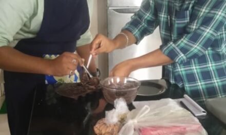
The process begins at least 24 hours before molding. Exactly 1/3 of the Shadu Mati (Natural Clay) is submerged in water overnight. It must be fully emerged to ensure the core of the clay particles is hydrated. The following day, this “wet” clay is mixed with the remaining dry clay in a mechanical mixer.
- The Artisan’s Rule: The mixture is adjusted by feel. If the mud is too sticky, dry clay is added. If it is too stiff, more of the pre-soaked wet mix is added. Ideally, the process is “dry-forward”—it is better to add dry clay to a wet mix than to add raw water to a dry mix, as raw water can disrupt the molecular binding of the Shadu.
Stage 2: Preparation of the Clay Sheet
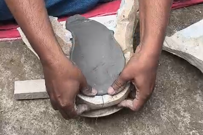
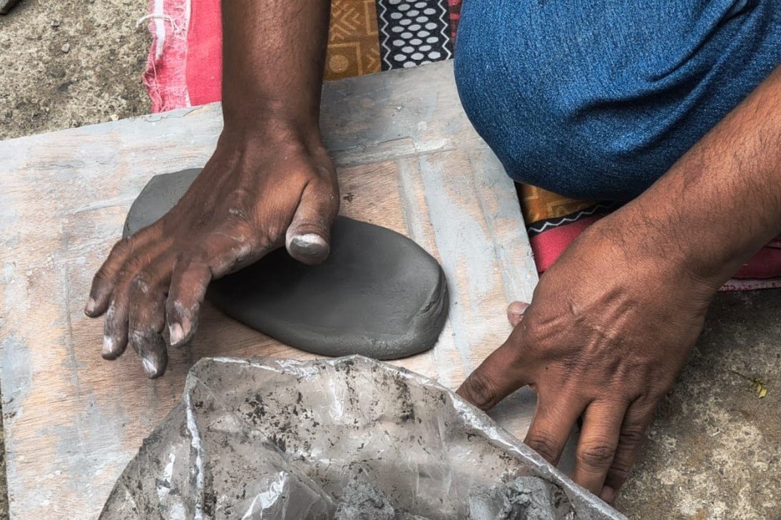
Once the consistency is perfect, the clay is flattened into a uniform sheet, similar to a large chapati. This sheet serves as the raw material for the mold.
Stage 5: Fusion and Assembly
The back piece of the mold undergoes the same detail-and-thickening process. Because the back has fewer details, it is faster but no less important. The pieces are then brought together. The artisan reaches inside the hollow center to press the mud against the joining edges, “fusing” the separate sheets into one solid body.
Stage 6: De-molding and Initial Curing
The idol is left in the mold for 5 to 10 minutes to “set.” It is then carefully de-molded. At this stage, the idol is “Greenware”—wet, heavy, and fragile.
Stage 3: The Primary Impression (Detailing Layer)
The mold (usually a 4-piece assembly) is prepared. For smaller idols, 3 pieces are joined first. A thin sheet of clay is placed inside. The artisan uses their fingers to press the clay into every deep crevice and corner of the mold.
- Crucial Detail: This first layer must be thin. If it is too thick, the pressure from the fingers won’t reach the bottom of the mold’s design, leading to “blurred” or missing details. This is the most skilled part of the process, as the artisan must intuitively know how much pressure is “enough” to capture the design without tearing the sheet.
Stage 4: Structural Reinforcement (Thickening)
Once the detail layer is set, additional layers of mud are added to provide structural integrity.
- Variable Geometry: The thickness is not uniform. Areas that handle high stress—specifically the neck (supporting the head) and the base (supporting the entire vertical weight)—are reinforced with extra clay to ensure the idol doesn’t collapse under its own weight when de-molded.
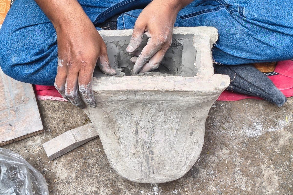
Stage 7: Fine Detailing and Limb Attachment
Any imperfections or “crease lines” from the mold seams are removed using a small art knife. If there are small gaps, they are filled with a “high-water ratio” mud (a paste consistency) which spreads easily with minimal pressure.
- Limb Integration: Since complex hands or external features can’t be easily molded, they are made separately and attached now. The artisan scores (creates scratches) on both surfaces and uses the wet mud paste as “glue.” For larger idols, wooden sticks are inserted into the limbs to provide a “skeletal” support to bear the weight at difficult angles.
Stage 8: Drying and Finishing
The idol dries for several days to a week. Once stone-dry, it is polished to a smooth finish and finally painted.
- THE CHALLENGES WHILE MAKING MURTIS The Time Bottleneck:
Currently, a single 1.5-foot idol takes between 1.5 to 2 hours of active manual labor. The molding/thickening takes 45 minutes, and the detailing takes another hour.
- Detail Loss: Because manual finger pressure is inconsistent, complex mold designs are often avoided because they are too hard to “fill” by hand.
- The Glue Factor: Attaching limbs is a slow process of ensuring the “glue” mud is the right consistency to prevent parts from falling off during the drying phase.
- Physical Strain: The constant pressing of clay into molds for 8–10 hours a day is physically exhausting for artisans, leading to a drop in quality towards the end of the day.
- CHEMISTRY AND BEHAVIOR OF SHADU MATTI
Shadu Mati is a unique natural clay with specific behaviors that must be accounted for in any machine design:
- Shrinkage: As Shadu Mati dries, it loses its water content and “cools,” causing the entire structure to shrink by 0.5 to 1 inch. Any mechanical mold must be slightly “upscaled” to account for this 5-8% contraction.
- Thixotropy: The clay behaves differently under pressure. It needs enough force to become “fluid” enough to enter design crevices but must remain “stiff” enough to hold its shape once the pressure is removed.
- Adhesion: Shadu has a high affinity for smooth surfaces, meaning de-molding requires perfect timing—too wet and it sticks; too dry and it cracks.
conclusion/define
(30-march-2026 to 10-april-2026)
This visit helped me in understanding the process of making shadu murti. the proccess, the steps, creativity, hardwork, efforts, the challenges, etc..
This proccess and understanding of it. provide few important things the data..
our goal was to reduce time some how. but for that we had to learn the process where we can cut down the time. and this understanding helped in there..
so, we obverseved the manual burden along the 8 step proccess. and here in few steps we can cut down the timme and manual labour. or atleast reduces the burden.
By reducing the burden, and making process fast labour can do more work in less stress and burden. so ultimatly time reduce for per idol creation.
so, few steps or stage is requiered as it is. cos it need that artist work into it. like fine work, detailing, coloring. the focus here is on the stage 3 and 4.
This is the longest process and high labour intensive process, highest manual burden.
this two stage does one same thing, giving the shape to the idol. so adding shadu in the mould and pressing it manually to get immpression and then rethicknining it with extra clay for structrual stability all this give shadu the shape of idol.
reason of first thin layer impression and than second layer thickening and more extra sadhu for stability, is that while doing it manually due to less force by hand we cant add thick layer of clay and press. it will be hard to get detail here. so they do it in layers. this cost more time. also manual burden tends to fatigue. and the energy reduce and work get affected due to it.
so if we work on this part which take max time and burden. we can reduce total time significantly.
we will be working on this part about how we can ease this step/stage of the proccess. how we can automate it or semi automate, using machine or discovering new method to to this steps….
our next step will be thinking of solution which reduce time in this perticular stage of the proccess. and amoung all the discover solution which is best…
thinking
(1-march-2026 to 20-april-2026)
In the previous section, we defined our problem statment whcih was the result of visit and understanding the current proccess of making shadu idols…
As we get to know that the first few step of making impression with shadu clay and making the shape of idol is the longest proccess and high effort included. and as we made decision to work around this step and reduce efforts and time here.
In this section of blog we will exploring different aproches we can go with. having multiple idea helps to make best decision and tends to best aproach.
1. DISCUSSED MECHANISMS & TECHNICAL INTERVENTION
From the start, we discussed many mechanisms with mentors and guide. we evaluated three distinct mechanical engineering approaches to replace the 45-minute manual molding phase. My intervention focused on balancing mechanical simplicity with the fluid dynamics of Shadu Mati.
Mechanism 01: The 4-Axis Robotic Articulation (Biomimetic Pressing)
This was discussed and consider on of the way before project was finalized (4 – march- 2026) and also discussed with benificiery on (23-march-2026). when first i was introduced to this project and we explore the posiblities, we had in mind that if we can mimic the same exact way of shaping shadu into murti as human do. with presize pressure, different angle flexibily, and the feel of shadu while operating.
Concept: Using a robotic arm show beside equipped with a specialized “End-Effector” (a silicone finger) to mimic the artisan’s way pressing clay into mould.
reasons : This would allow for pressure from multiple angles, just like human presses in all place in angle and direction.
this will mimic exact method of human. how an artist press clay into mould and get impression. the same way this robotic arm will do and much more fast.
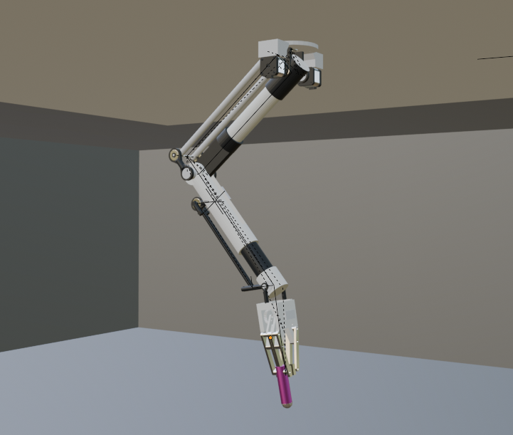
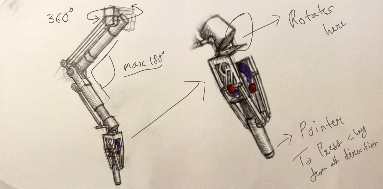
technicals: the robotic hand can manuver in all direction reach crital angles. with the help of motors. the top rotate full 360 degtree. which helps hand to reach all direction in an hemi-sphere.
the pointer is made of silicon, it also have pressure sensor in it so it give feedback of the pressure. which help to mimic gentle handling of human hand. The sensor allow robotic arm to feel the shadu/ clay. just like an artist feels it and apply pressure accordingly.
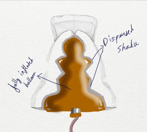
Mechanism 02: The balloon inflat into closed mould.
This was discussed and consider on of the way before project was finalized. when first i was introduced to this project and we explore the posiblities, we had in mind that if we can mimic the same exact way of shaping shadu into murti as human do. with presize pressure, different angle flexibily, and the feel of shadu while operating.
Concept: Using a robotic arm show beside equipped with a specialized “End-Effector” (a silicone finger) to mimic the artisan’s way pressing clay into mould.
reasons : This would allow for pressure from multiple angles, just like human presses in all place in angle and direction.
this will mimic exact method of human. how an artist press clay into mould and get impression. the same way this robotic arm will do and much more fast.
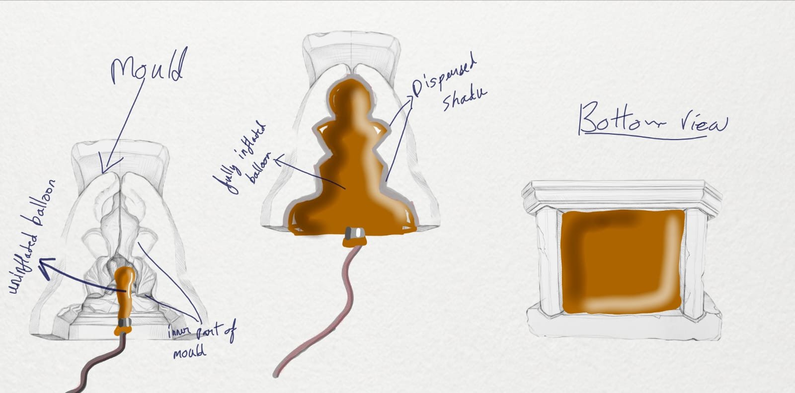
Your content goes here. Edit or remove this text inline or in the module Content settings. You can also style every aspect of this content in the module Design settings and even apply custom CSS to this text in the module Advanced settings.
Mechanism 03: Pressing each part seperatly under press machine
This was discussed and consider on of the way before project was finalized. when first i was introduced to this project and we explore the posiblities, we had in mind that if we can mimic the same exact way of shaping shadu into murti as human do. with presize pressure, different angle flexibily, and the feel of shadu while operating.
Concept: Using a robotic arm show beside equipped with a specialized “End-Effector” (a silicone finger) to mimic the artisan’s way pressing clay into mould.
reasons : This would allow for pressure from multiple angles, just like human presses in all place in angle and direction.
this will mimic exact method of human. how an artist press clay into mould and get impression. the same way this robotic arm will do and much more fast.
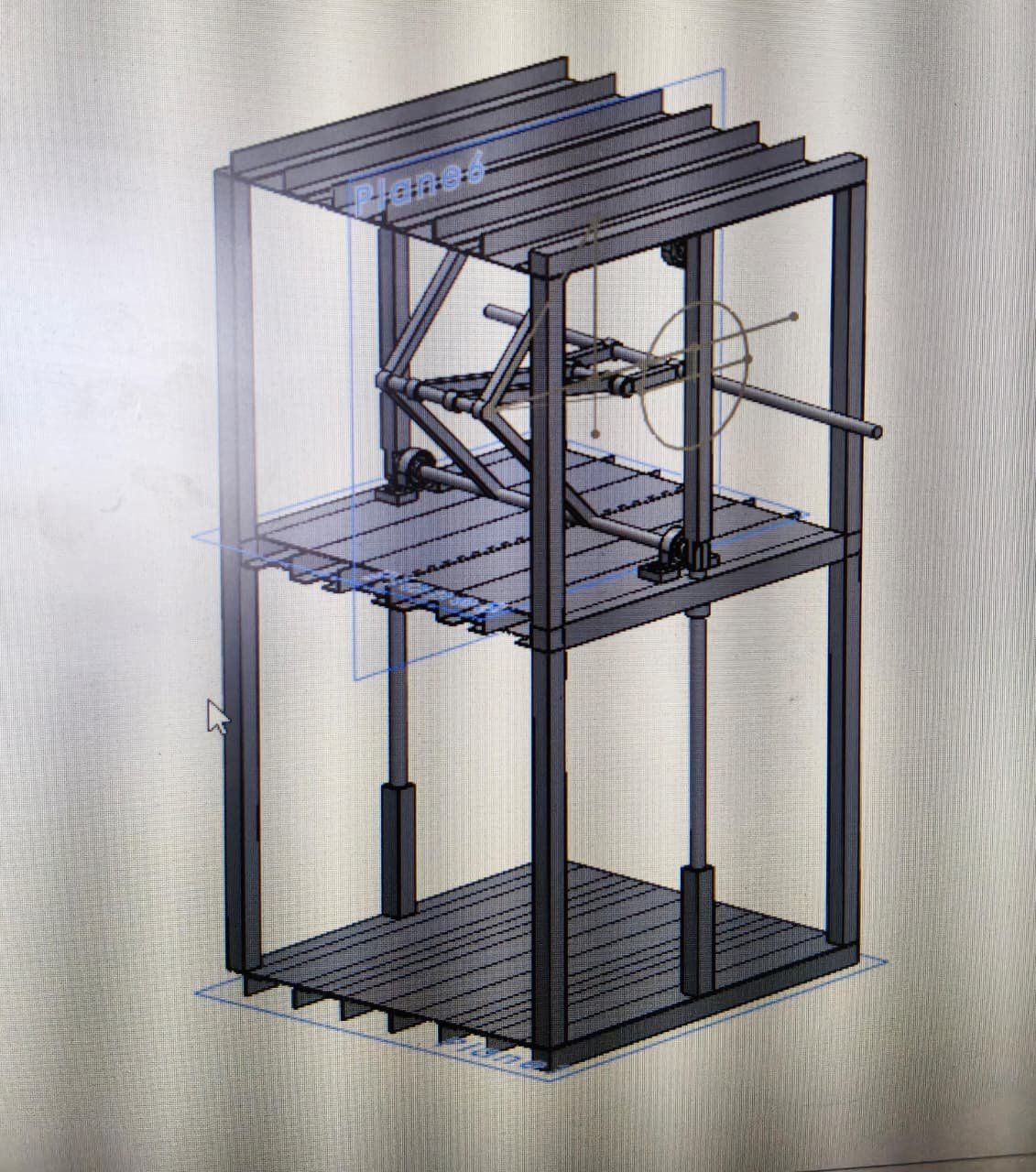
Your content goes here. Edit or remove this text inline or in the module Content settings. You can also style every aspect of this content in the module Design settings and even apply custom CSS to this text in the module Advanced settings.
decision
(17-april-2026 to 20-april-2026)
Your content goes here. Edit or remove this text inline or in the module Content settings. You can also style every aspect of this content in the module Design settings and even apply custom CSS to this text in the module Advanced settings.
Your content goes here. Edit or remove this text inline or in the module Content settings. You can also style every aspect of this content in the module Design settings and even apply custom CSS to this text in the module Advanced settings.
prototyping
(25-april-2026 to 10-may-2026)
As we concluded to go with pressing each mould piece method. we need to again ideate and think the aproaches while building this prototype.
think of the way how we design the machenism, how it will press. the claleenges, the solutions.. we have to again filter the methods. but this time it is related to perticular mechenism. before we made decision martix for selecting the machenism. here in the journey ahead while prototyping. we have need to take decision for aproaches towards the machenism.
method overview
in this method we will be using press machenism. as the idol shape is complex but as our mould can be saparated and is consist of 4 part. the 4 direction front, back, right and left. and we can press each seperately and than combine it to form full idol.
Existing Mould.
so, the current mould consist of 4 parts show in the below images. and combines and form full mould.
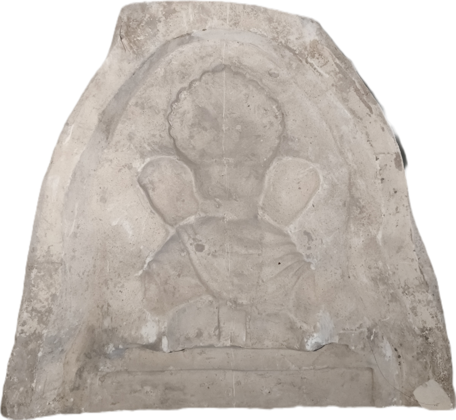
BACK SIDE
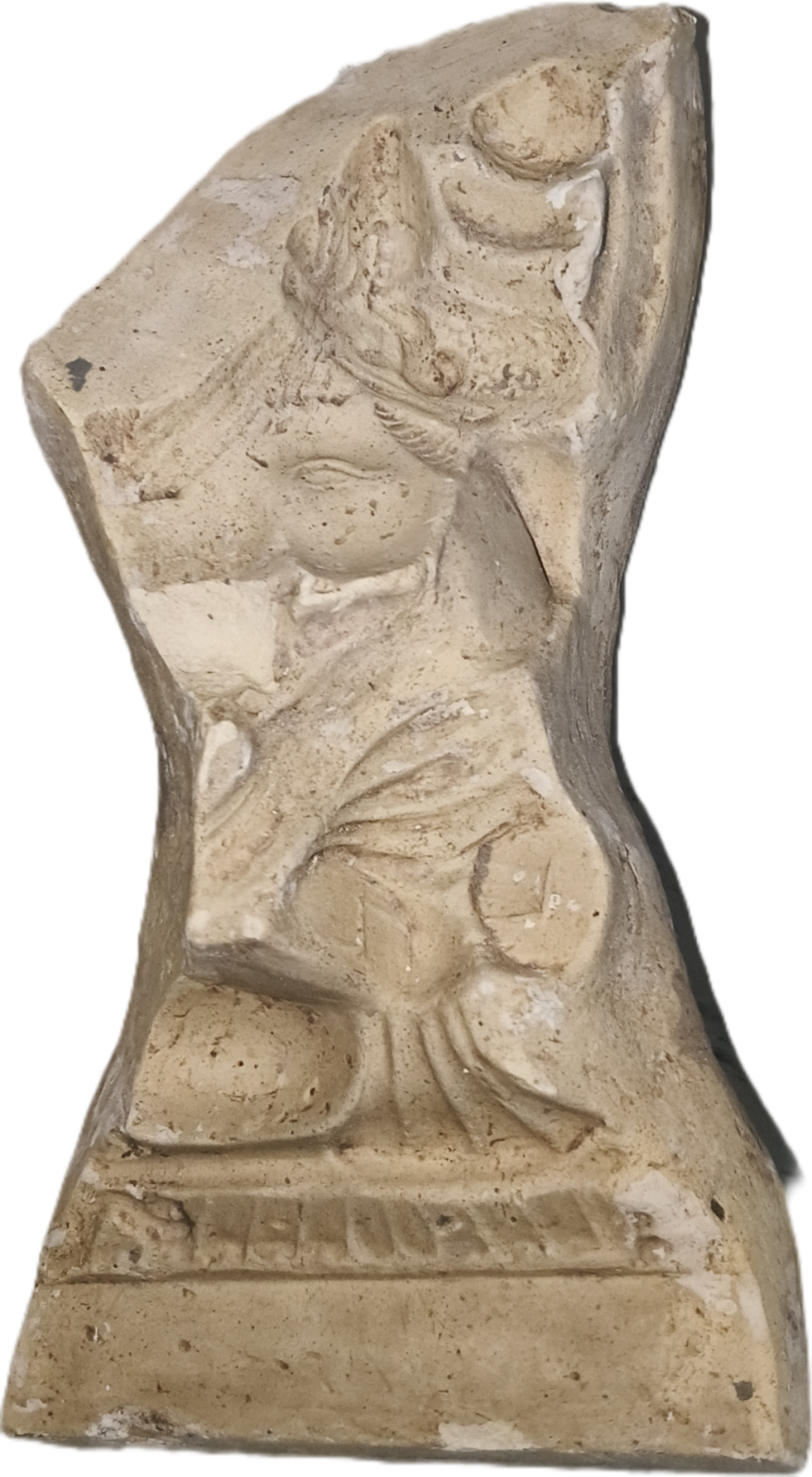
RIGHT SIDE
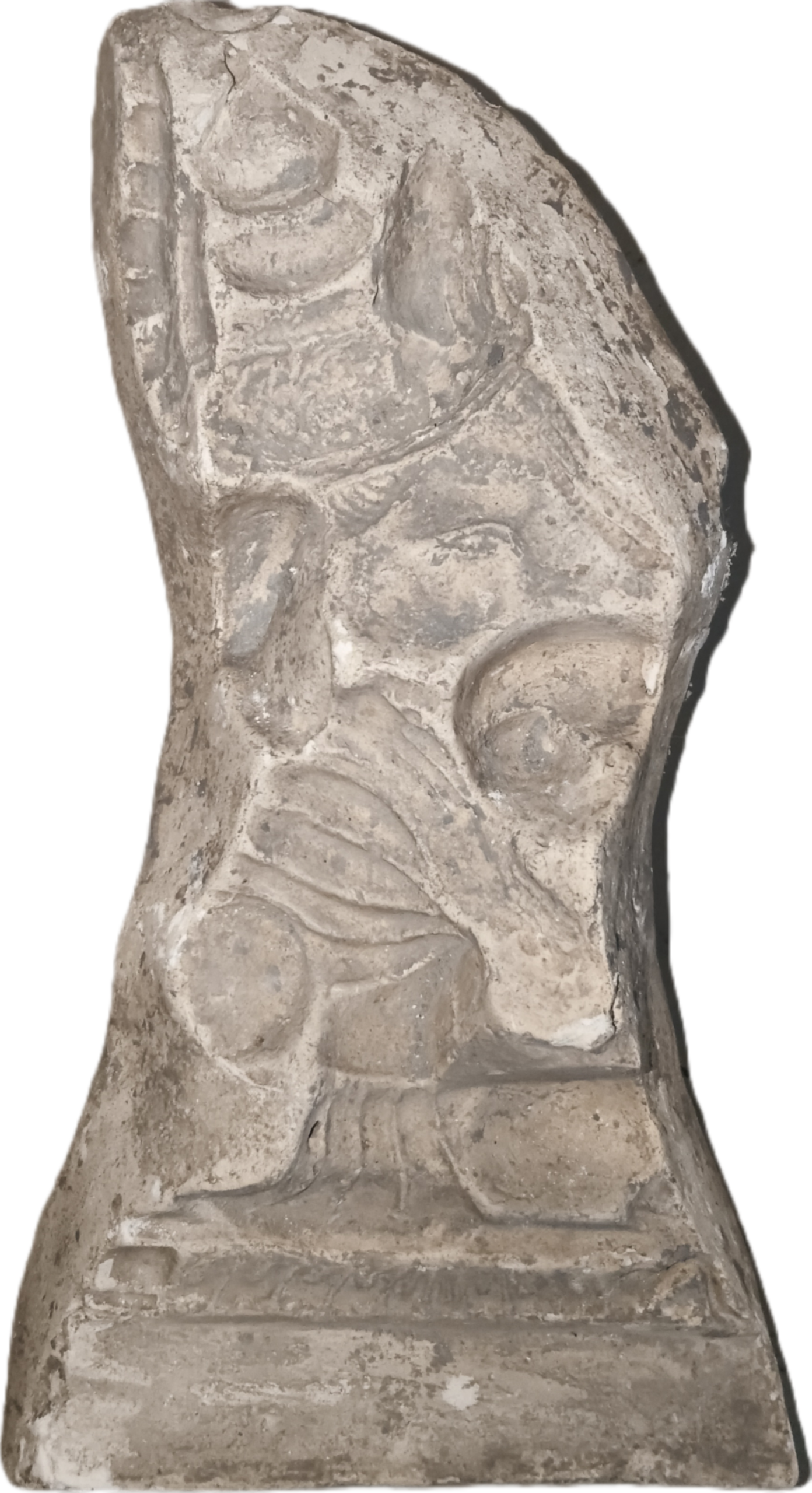
LEFT SIDE
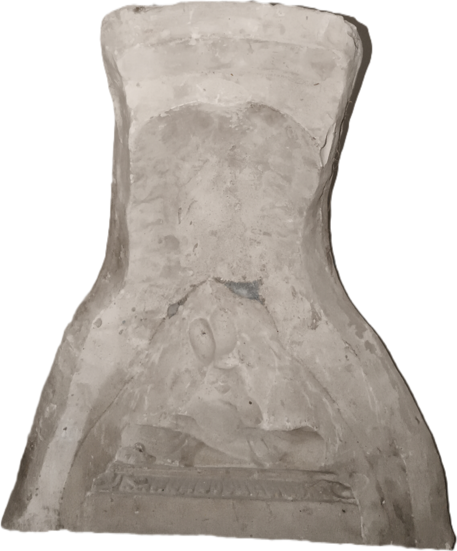
FRONT SIDE
as shown in the below image. this is how it is assembled. this eaxct shape or how it assemble and disssemble. this allows us to unmould the idol properly. this is how existing mould works.
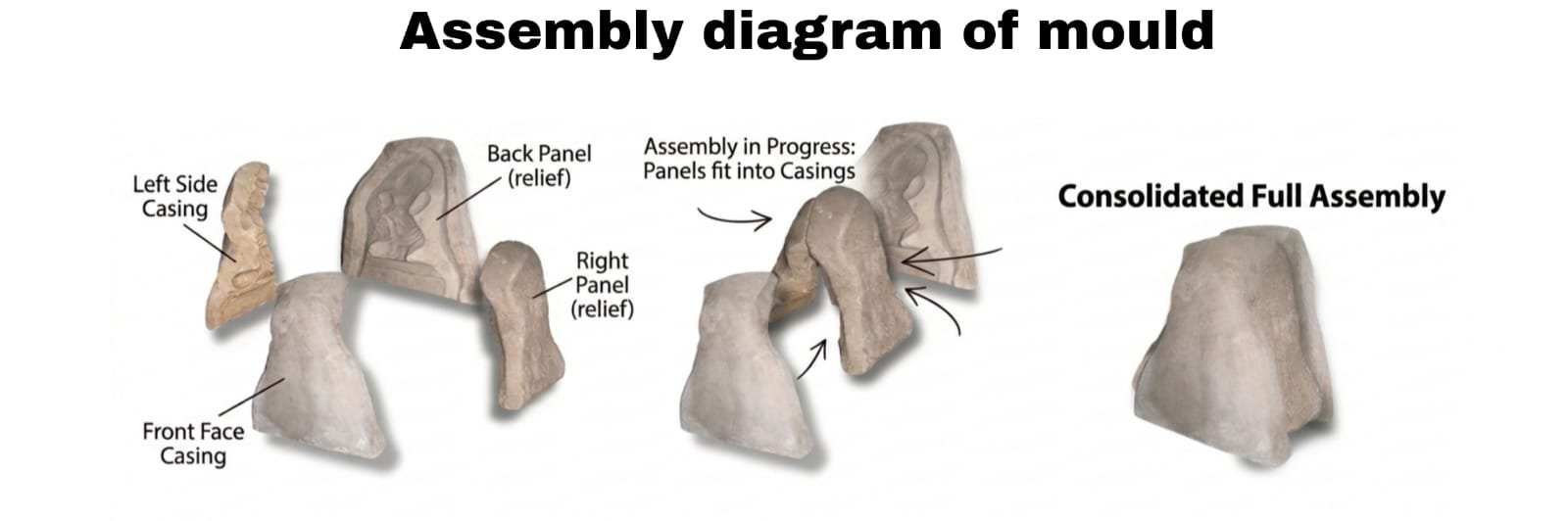
SO, the thought around this mould is that make impression on each piece seperately. and than assemble it like puzzle again. after it get attached unmould to get complete idol.
in this way worker, artist the steps dont changes too much and morker or artist is already have practise of such task. they dont need to adapt to new proccess differently. our method just let artist skip one-two steps and continiue ahead. and our method dont need to be learned, so easily slips into artist proccess without overhead.
press system
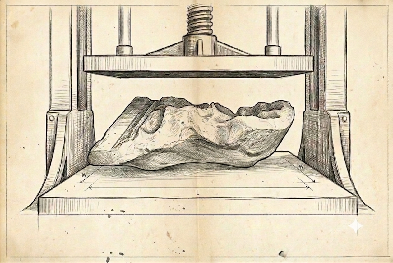
pressing mould need mould pieces to be placed on the table or flat bed. and from the top there will be a top plate which will have nigative or core of the mould piece. which will travel down and press to our part and will make impression.
we will put the shhet of the shadu clay between or on the mould. when the top plate compress the clay. the clay will make an impression in the mould piece.
reapeating this to all four piece will give us all the ready parts. and than we can just assemble it later to form full idol.
problem
(25-april-2026 to 27-april-2026)
As we visualize and think of practical implementation which was done on 26th of april . we discover the problem. and this problem is needed to be solved before we move ahead.
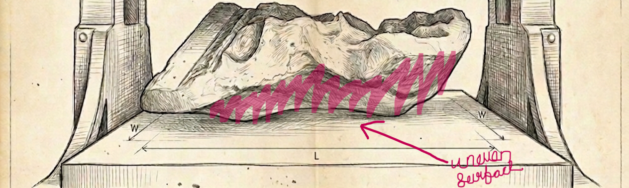
The problem here is the mould piece in not flat.
As it has uneven shape. placing on the flat bed and pressing will damage the part. it will break in an instant. here we need a solution how we can make mould sit on flat bed and stable.
solution to previous problem
as on the same day while discussing the problem, we thought of few solution.
We will be needing to make mould flat from below, so we can place it perfectly flat on the flat bed. we decided to make a place holder for exiting mold. Mold for Mold.
there were few important thoughts. how do we make it, in which material we have to make. cos the proccess and method will totally change on material we will be working with.
below are the few thought and method around those placholder mold…
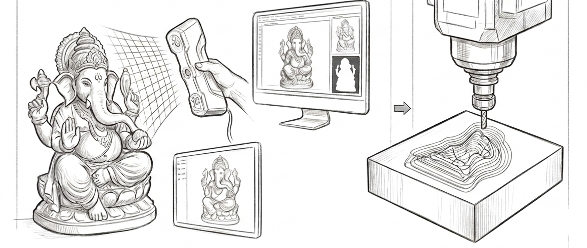
Fully Metal Mold
-
Step 1: 3D Data Creation Create the digital asset either by designing it directly in 3D CAD software or by 3D scanning a physical idol.
-
Step 2: CNC Metal Milling Convert the digital model into toolpaths and use a high-precision CNC machine to directly carve the inverted cavity into a solid metal block.
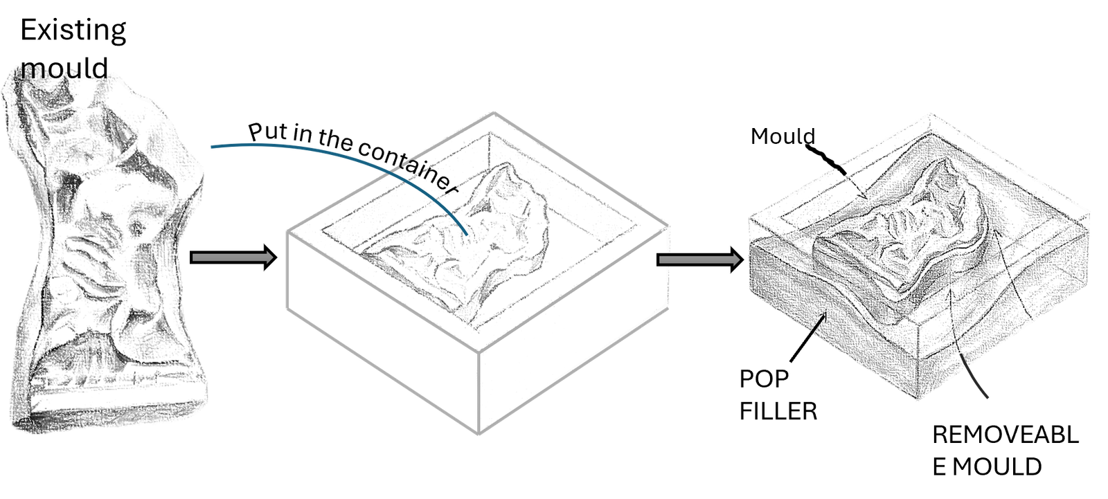
Metal ReEnforced Filler Mold
-
Step 1: Mold Acquisition Source a standard, existing market mold or create one using traditional manual methods.
-
Step 2: Container Placement Position the traditional mold securely inside a rigid metal container.
-
Step 3: Filler Element Reinforcement Pour a backing filler mixture (such as POP, concrete, or dental gypsum) into the container to solidify the base and reinforce the mold structure.
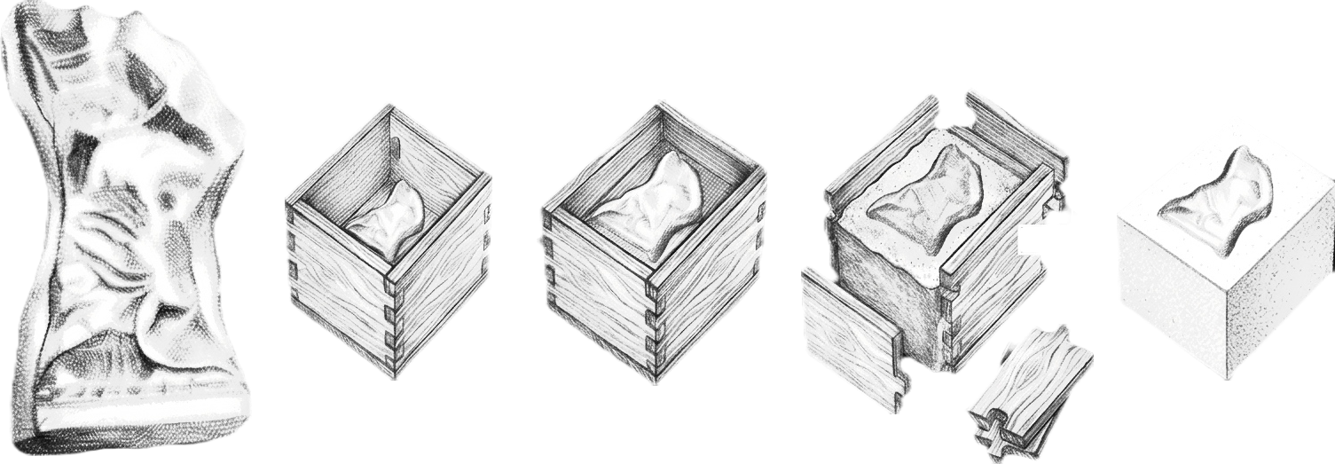
Fully Gypsum Mold (no metal)
-
Step 1: Mold Acquisition Source a standard, existing market mold or create one using traditional manual methods.
-
Step 2: Container Placement Position the traditional mold securely inside a puzzled wooden container.
-
Step 3: Fill gypsum into the container till solidify.
-
Step 4: Unpuzzle the wooden container
decision
(29-april-2026)
Your content goes here. Edit or remove this text inline or in the module Content settings. You can also style every aspect of this content in the module Design settings and even apply custom CSS to this text in the module Advanced settings.
Your content goes here. Edit or remove this text inline or in the module Content settings. You can also style every aspect of this content in the module Design settings and even apply custom CSS to this text in the module Advanced settings.
mold prototyping
(30-April-2026 to 8-May-2026)
for start building the mold prototype. we again need to do some empethy understand the mold making, define to a point conclude things we learn, and than start building the prototype the fabrication. here the design thinking first step came again.
i am talking about design thinking here in this section in this stage has reason. first, i get to know this on this stage. second it is important to get to know on this stage.
- extra inportant *
the design thinking is not the way most of think. not as straight ass it is. the fundamental method is same. but some people just think that it is aplicable to only one way. or only for projects.
Empathize (understanding user needs) –> Define (stating the core problem) –> Ideate (brainstorming solutions) –> Prototype (building scaled-down models) –> Test (gathering real-world user feedback)
here it seem that we just apply it at starting or just at bigger picture.
but what i learned while working on this project is,
Empathize (understanding user needs) –> Define (stating the core problem) –> Ideate (brainstorming solutions) –> Prototype (building scaled-down models) [Empathy (understanding the design technically) –> define ( methods, concept ) –> ideate (unify, approach) ] –> Test (gathering real-world user feedback)
design thinking works for project, bussiness, teaching, relations. anywhere where you need to handle thing smartly, we do design thinking.
we can break down the project and cycle the design think method in each steps shown above.
- back to mold press
so, we will be trying to understand what we are going to make. this part the mold is a part of the project and most important peice of the project. without this we cant move ahead. we need to unnderstand what actactly we need, how people in market does thing like this, what are the diffrent method for making molds.
understanding
i started researching how mold are been made. the different methods of mould making in diffrent industries.
- in many industry currently silicon molding method is famous like for art, sculpture, models, etc
- 3d printing
- handmade and than made mold out of it for replicas like for ganapati, sculptures.
here to mention, one might get confuse that we already desiced that we have to make pop mold. than why we are taking about silicon mold, or 3d printing.
so, we are exploring the method and technique for making mold. the proccess to understand mold making. and mold is usaully made for something we want to replicate like a idol, sculpture, parts, etc. but our case is different we have the part and we dont have to replicate it rather we have to make a place holder for it. mold for a mold. and here we dont eaxctly know what we have to do for it.
below are few refrence video of the proccess of making mould.
1
2
below is how eco friendly ganapati pop mold is made.
so, after exploring multiple methods i got somekind of idea how mould making works and how i suppose to make my mould. so in the first video/ video no.1 it was show a method called block mould.
so the method here is that around the part we create walls a container top open. and place part in the center and than pour silicon fully submerging the part fully. as silicon is felxible the part can be removed easily.
but in our case we have to make it in two part hlaf -half so, two part top negative part and bottom press in between. like soap making or Diya making moulds.
below i am giving both video how they work. i saw once.
so, as in the above video, there is mould in two part top and bottom. toghather pressing make the part ready. as we are working with similar material as in diya making, the clay. making parts of ganapati in similar way can be possible.
now that we have a direction to work on we have to conceptualize what exactly we have to do. cos our case is different. we cant just copy one of the method. we have to understand our part what we have what we have to make and think the way to work with it.
conceptualizing
(1-May-2026)
Day 1 of making mould
As from the learning and understanding our exiting mould shape. i have decided few thing which should be consider and act accordingly.
so form the observation. by looking at mould the thought came that we cant just place the mould and fill the surrounding area. and till where the pop is needed to be filled. in the below image noticed that all the part when assembled are not straight perpendicular to ground its like pyramid.
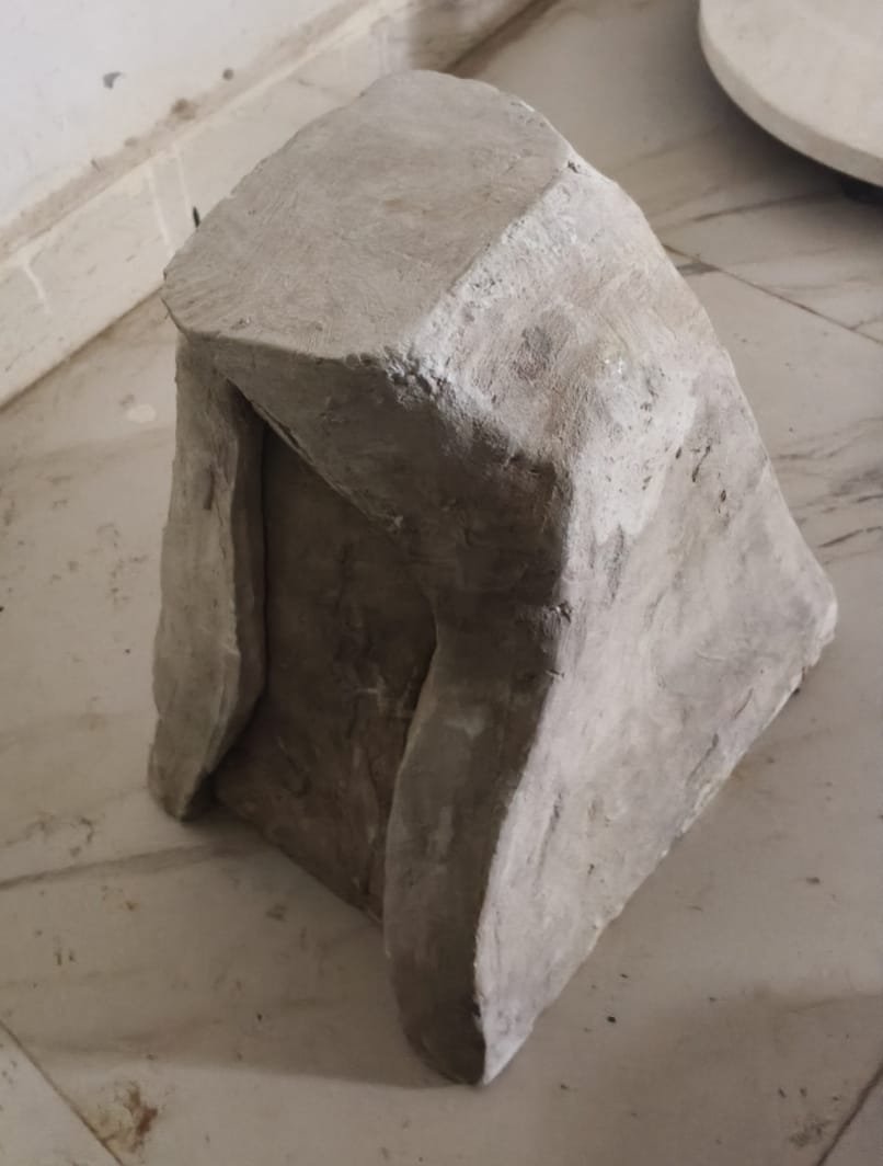
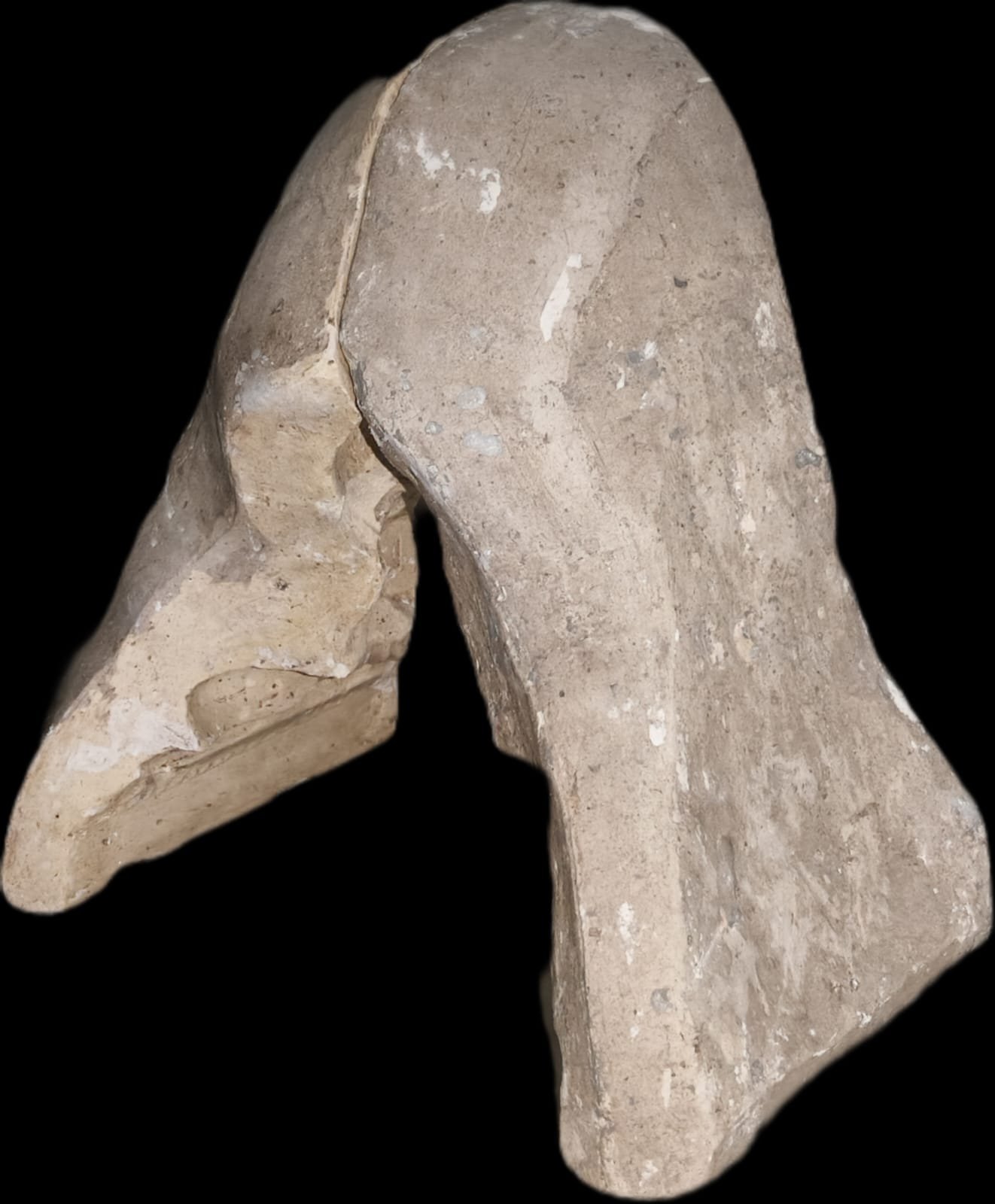
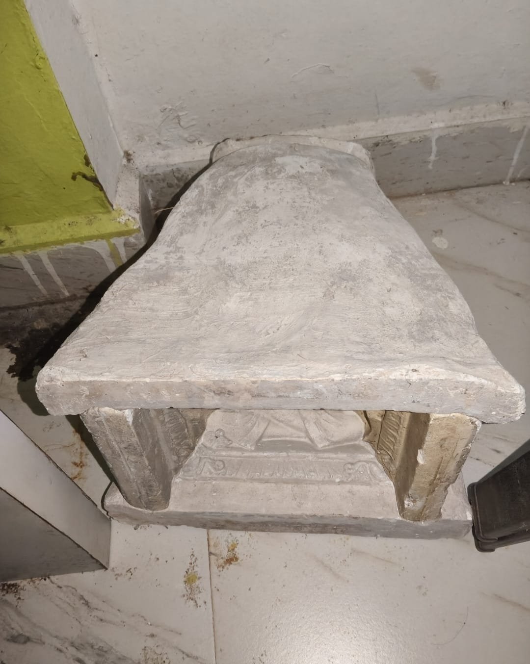
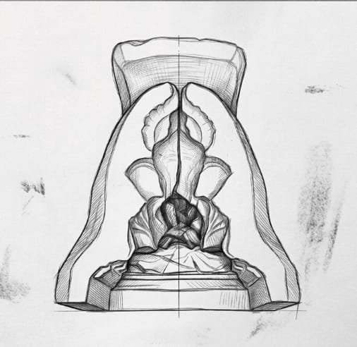
by seeing rom front intersection it easly noticable that the base is wide and the head top in small so it is converging from base to head at center.
Here we cant just put it on the flat surface. resting completely we need to putting it in an angle.
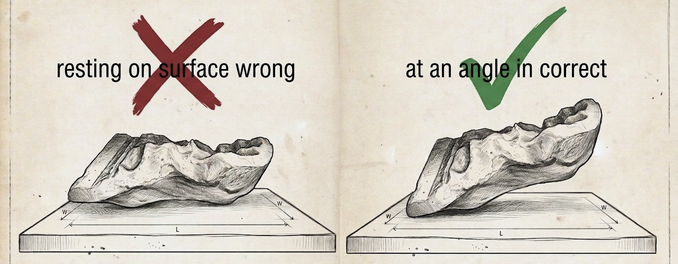
next thing is that we cant just pour pop in the container we have to shape it. we have to fill is according to the border of mould.
the edge of the mould is not linear. its curvy. as well as at angle too. so just pouring might not work.
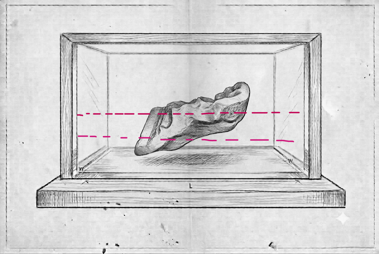
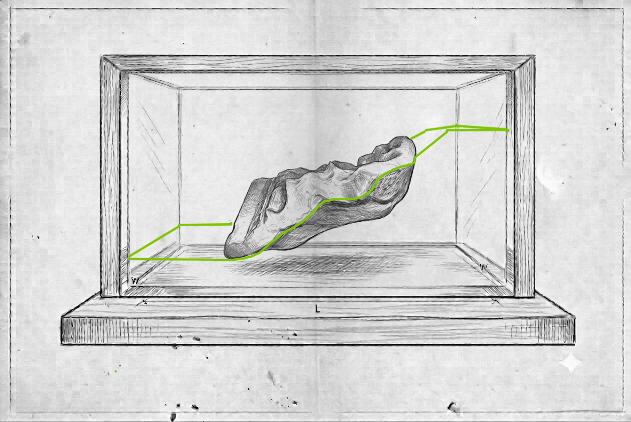
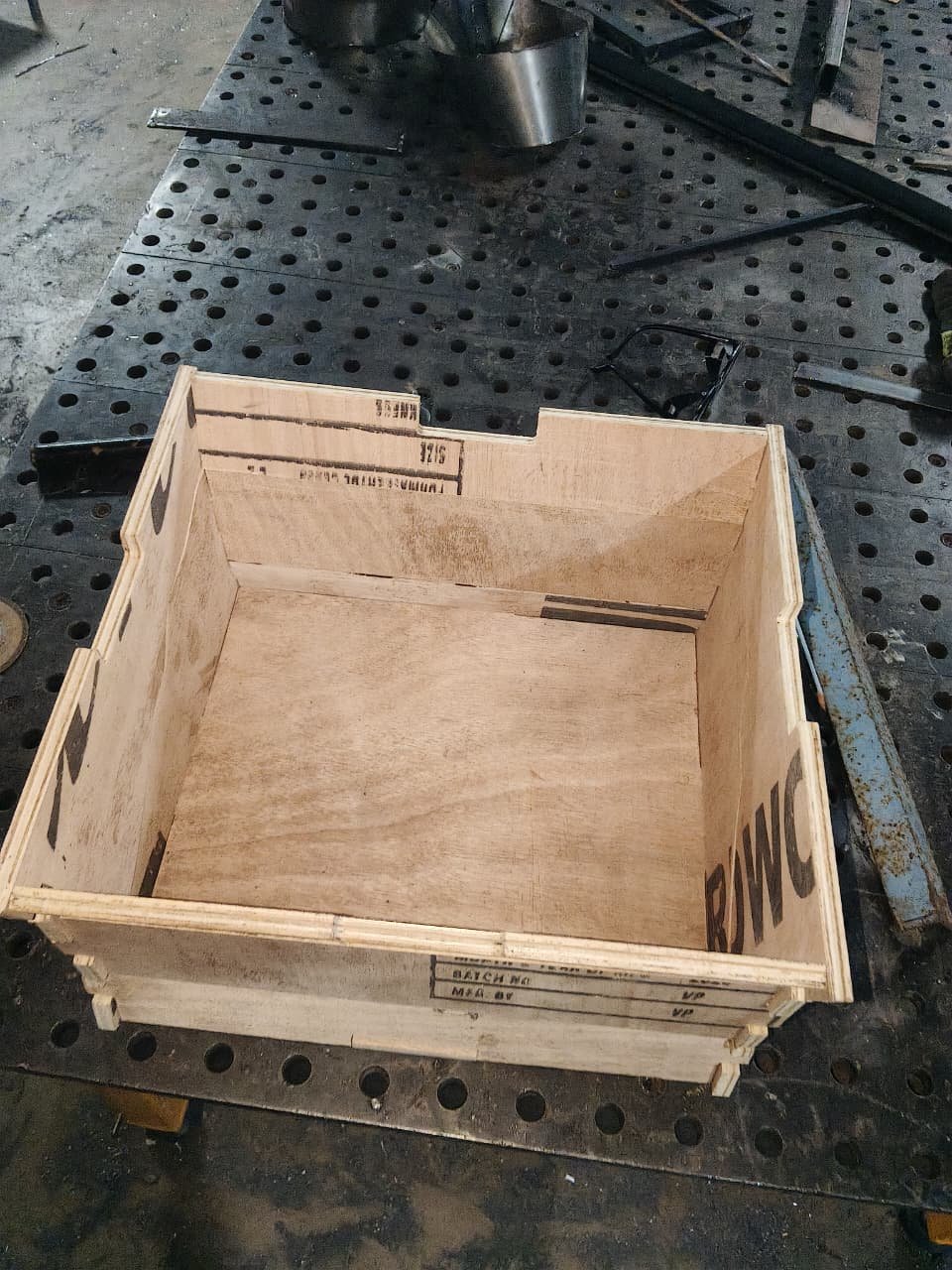
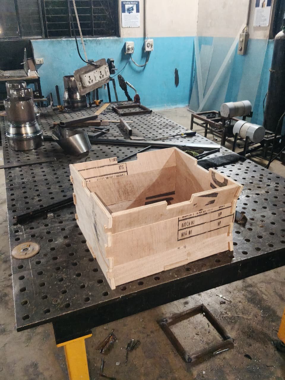
later we started making container, for this we decided to make it from wood. and cnc cut it. thinking of it i thought to make it like puzzle and easy to remove. detachable.
so, i started 3d modeling the how mould shape should look like. the first thing was just box like a puzzle. i already had this tought from before. and mentioned erlier.
but here this type will not be fixed to press system. as there will be two mould top and bottom. and it need to be fix properly aligned. so to hold the mold at a place. we need to think of something. few thought were
- add screw inside while pop is setting
- add horizontal rod. comeing outside of mould
- make shape of the mould in such a way it that we can make holder later.
shaping the mold sound good idea, it wont damage the mold and easy to use. the way i was thinking.
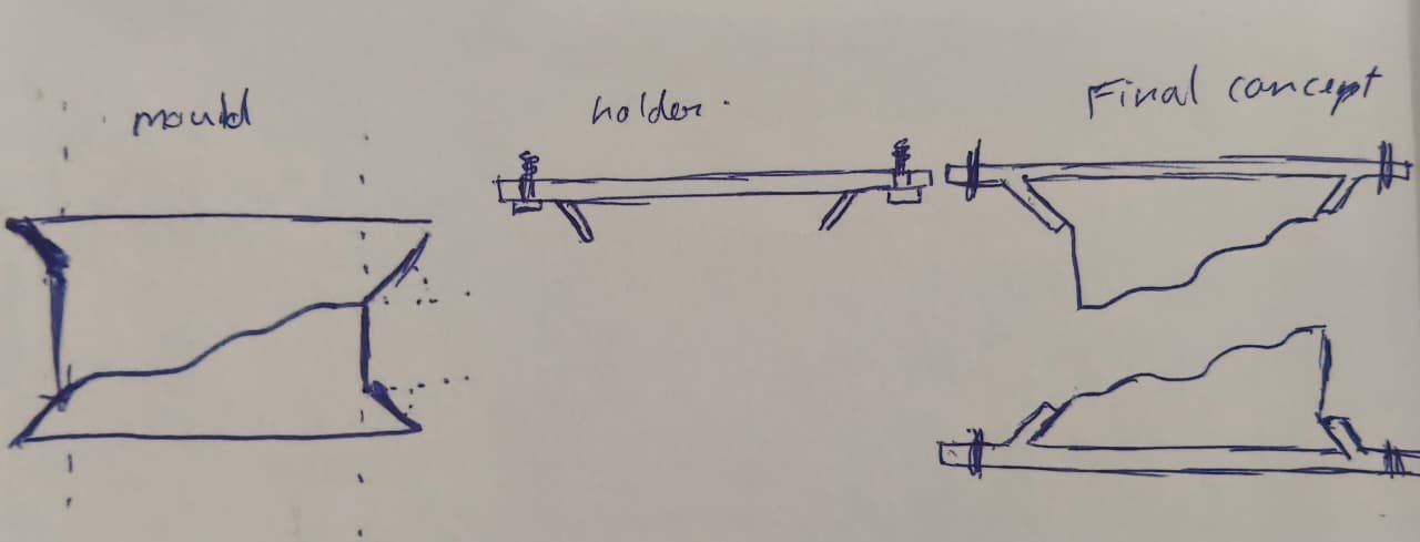
Day 2 of making mould
2nd-May made cad for mould container. for wood cuting in cnc wood router machine.
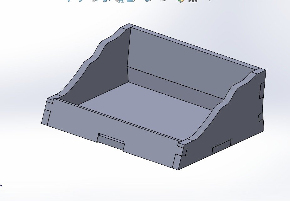
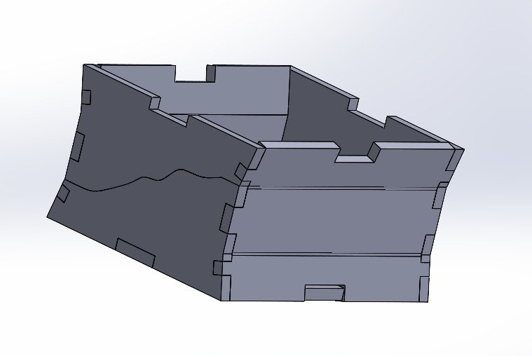
in the container we can fit 2 mould piece. right side and left side, as those two are small in size.
3rd day of making mould.
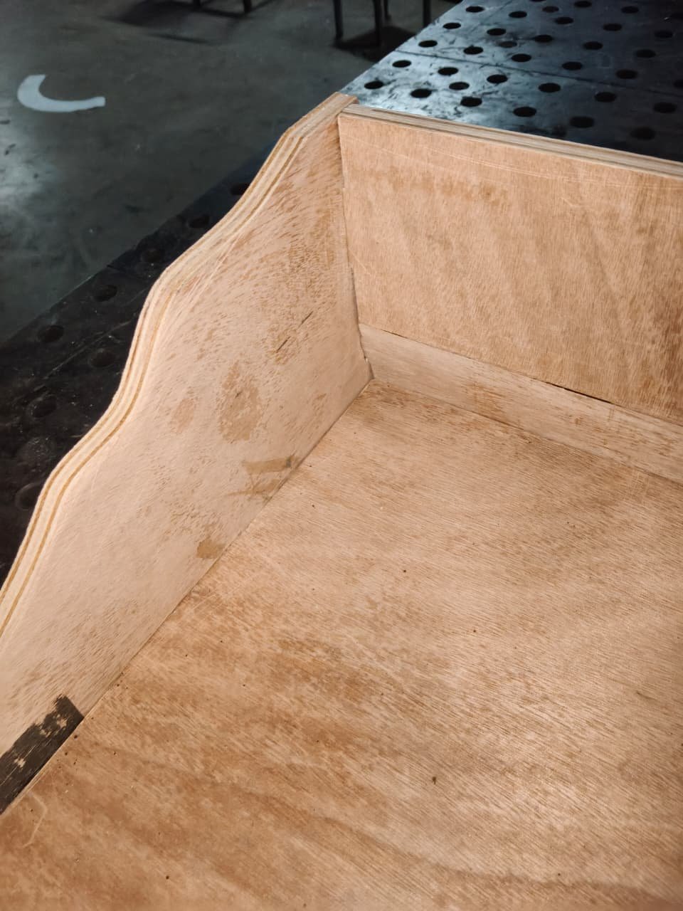
today May-3rd we successfully made our container parts. we used wood router cnc machine to do so. while doing this. there got some problem with operation. the 2d design of each piece was design acurately. but while cuting as the bit size is 6mm the thought was do we have to make our design 3mm wider from all side. as my friend already operated it before he told to resize the design and what i did waas select all and scale. but the out edges got bigger as needed and inner edge got smaller. in puzzle one part has outer edge and one part has inner edge and they should match. but here out got bigger and inner got more smaller. it didnt fit after pieces were cut.
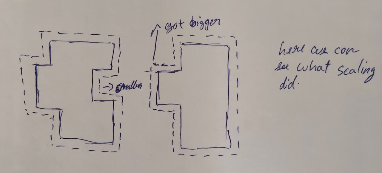
here still it should have worked if it used the path from center. but later we realised software is already feeded with bit size and it automatically shifts its center accordingly.
so, revert the changes done and correct 2d path given to the cnc. we got our container parts ready and we aassembled it. it took another day.
we successfully made our mould container on 5th May
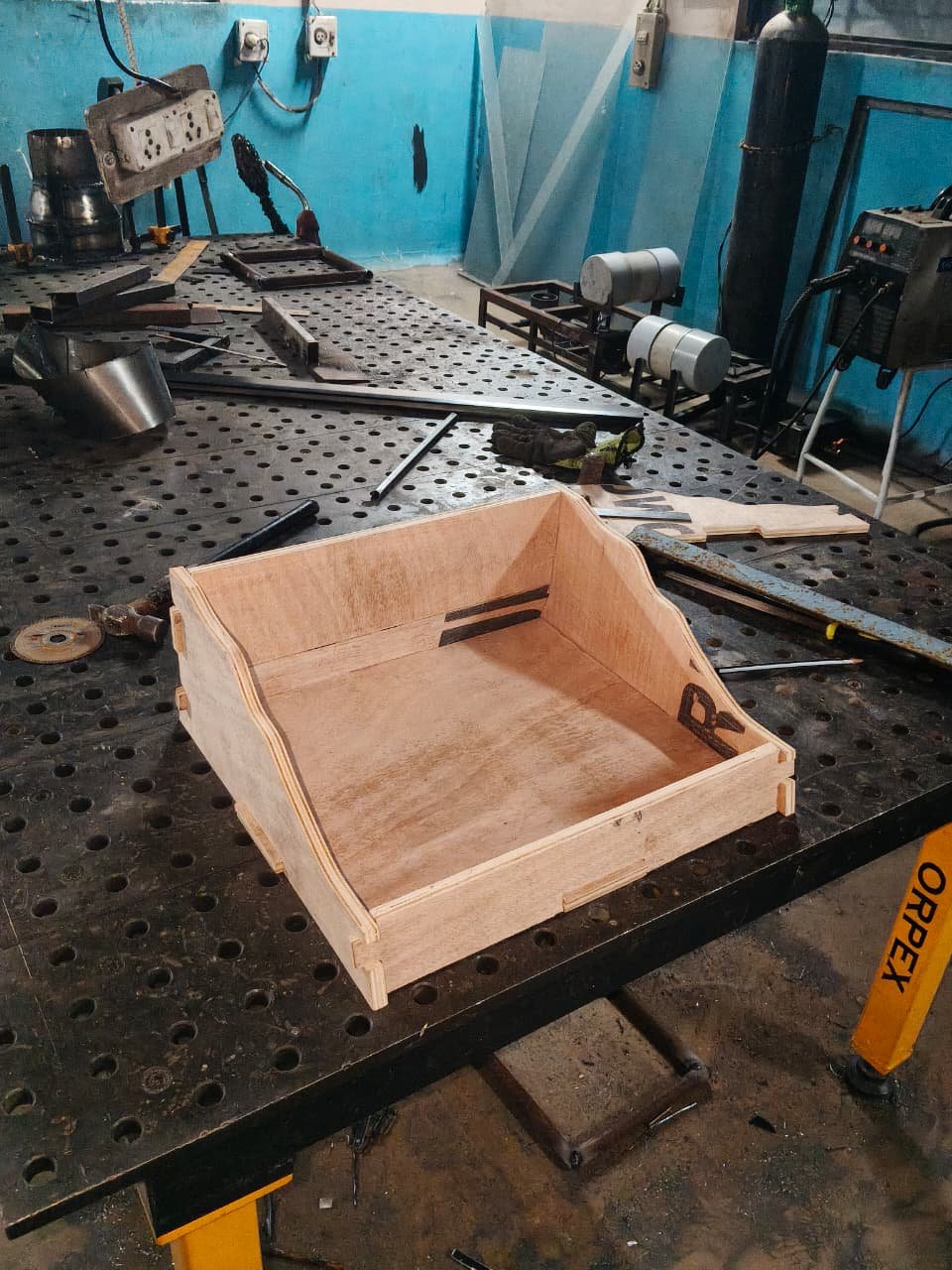
day 6th of mould making
We started makingour mold. as we know we have to we our existing mould at angle. and we have to fill the pop at different different height. we can just place the mould and pop the pop. the idea was to do it layer by layer. The consistency should not to too thin. and not too thick so it dont flow to harder to reach surface.
so, we first gres the surface. as the wood obsrobs the water. the pop might stick to it. do it need to be gres with wax. i used gres for it. also i gres the existing mould too. than as holding the part by one hand and puting the pop around the mould. added lil lill pop around it. and let it hold the mould. after the mould was stable at an angle we lil by lil started adding more pop around it. and started fill the container. waited few time at some height. than started again thanshaped it lil at higher height than again waited to dry. and repeatedly did the same.
shaping it lil by lil. but it was already exuasting and time consuming.
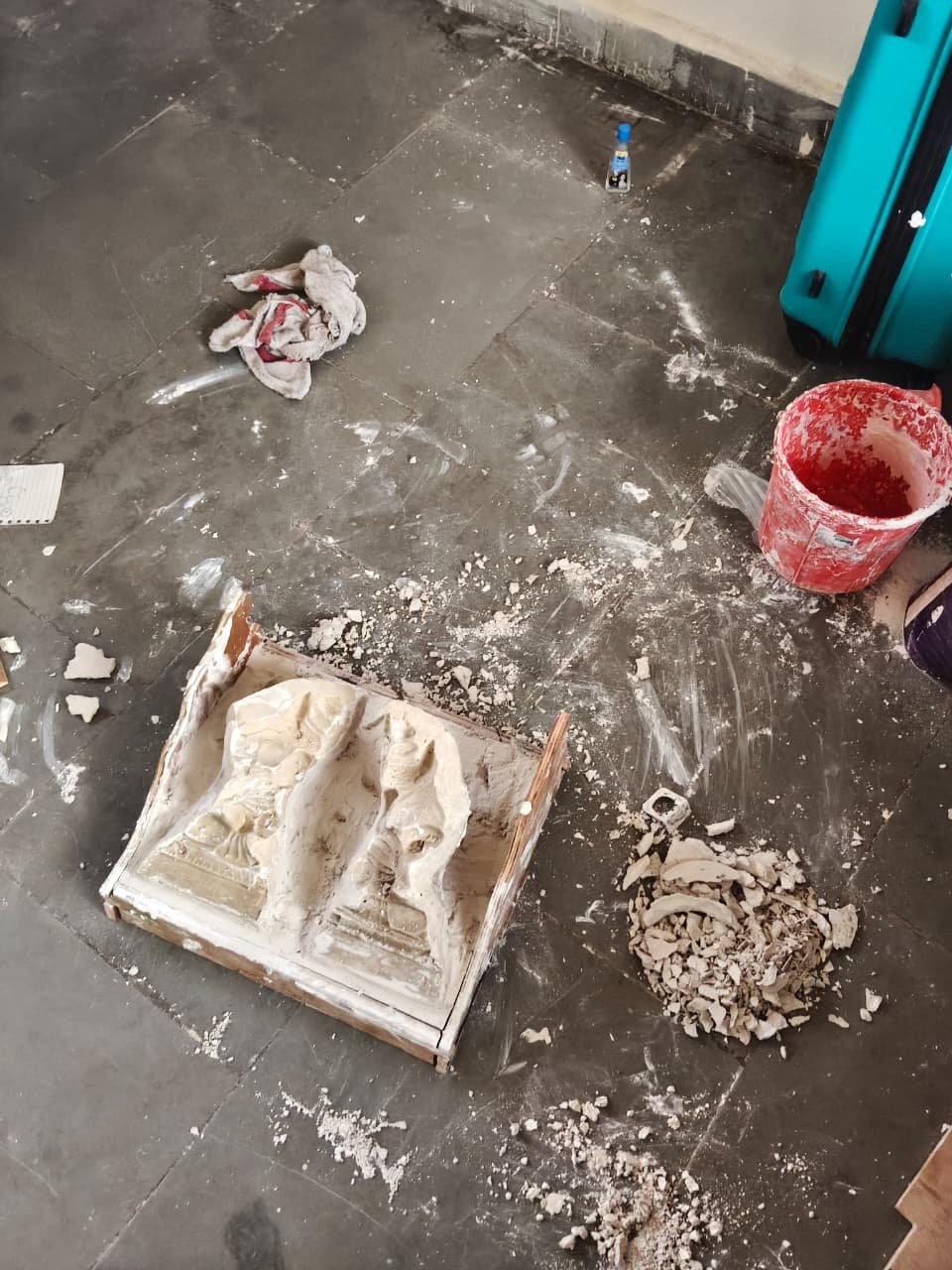
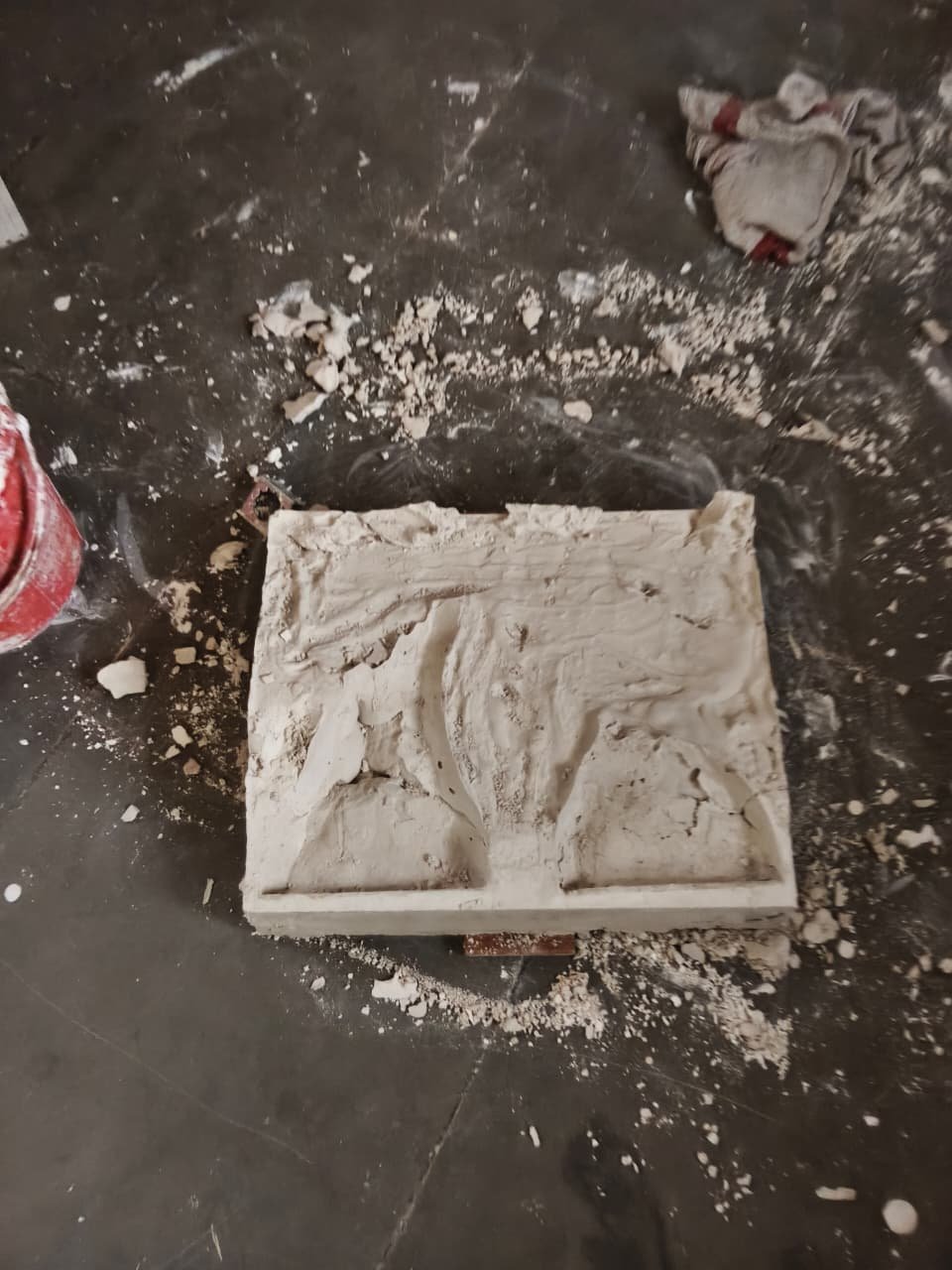
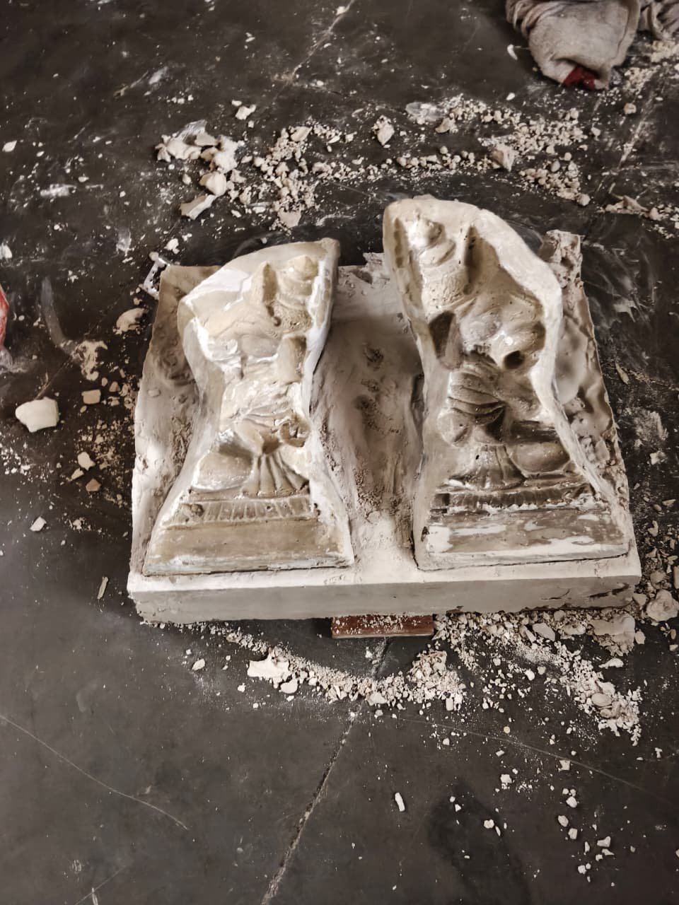
Here the quality was also not that good.
before completing it fully i stopped. if making a single mould would be too time consuming it will be hard to make. though this place holder it one time make and reuse it all time. still the method of making it dont seem good.maybe we can do it better. somehow we just pour and done.
i started focusing on how we can just pour pop. and it fills at different height.
here in this video before also we saw it. gave me click. seeing video onces will not get to the point, because the process seem time taking than how i am comparing it with fill. is not a direct technique shown in video. but using one method in diffrent way.
like here to set pop in perticular shape they uses shadu clay to form border around the idol. maybe we can aslo make the top cover of the shape we want.
we cloud have made top covering of that complex shape outof 3d printing, or any other different mordern method,. but making it easy and less complex way. grounded way where less technology is used was in the mind.
so, one option was to make a full sheet the sixe of container and than cut the shape of the existing mould in between. but yet balancing that big sheet was hard task. so thought to make it cover with small strips.
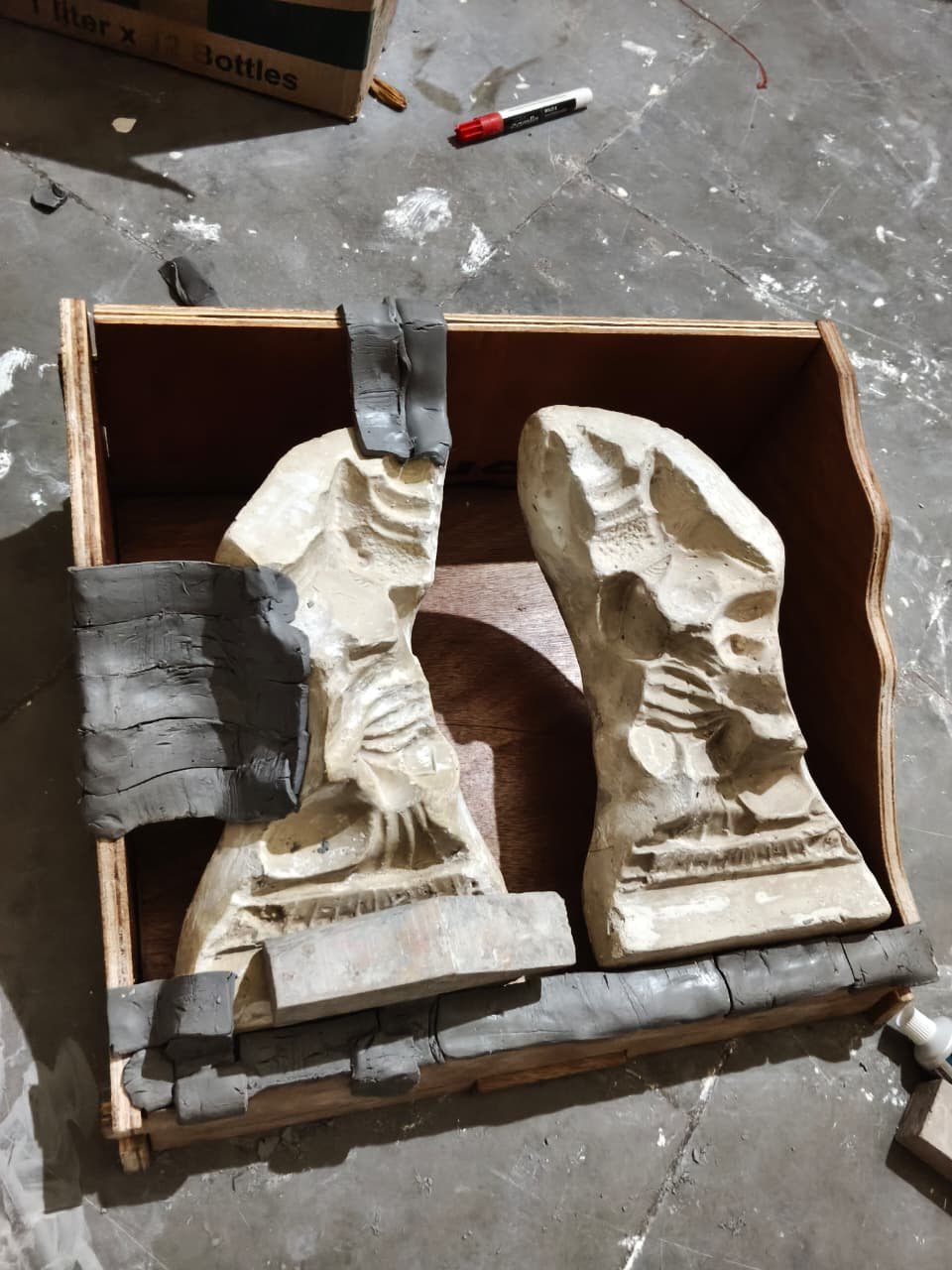
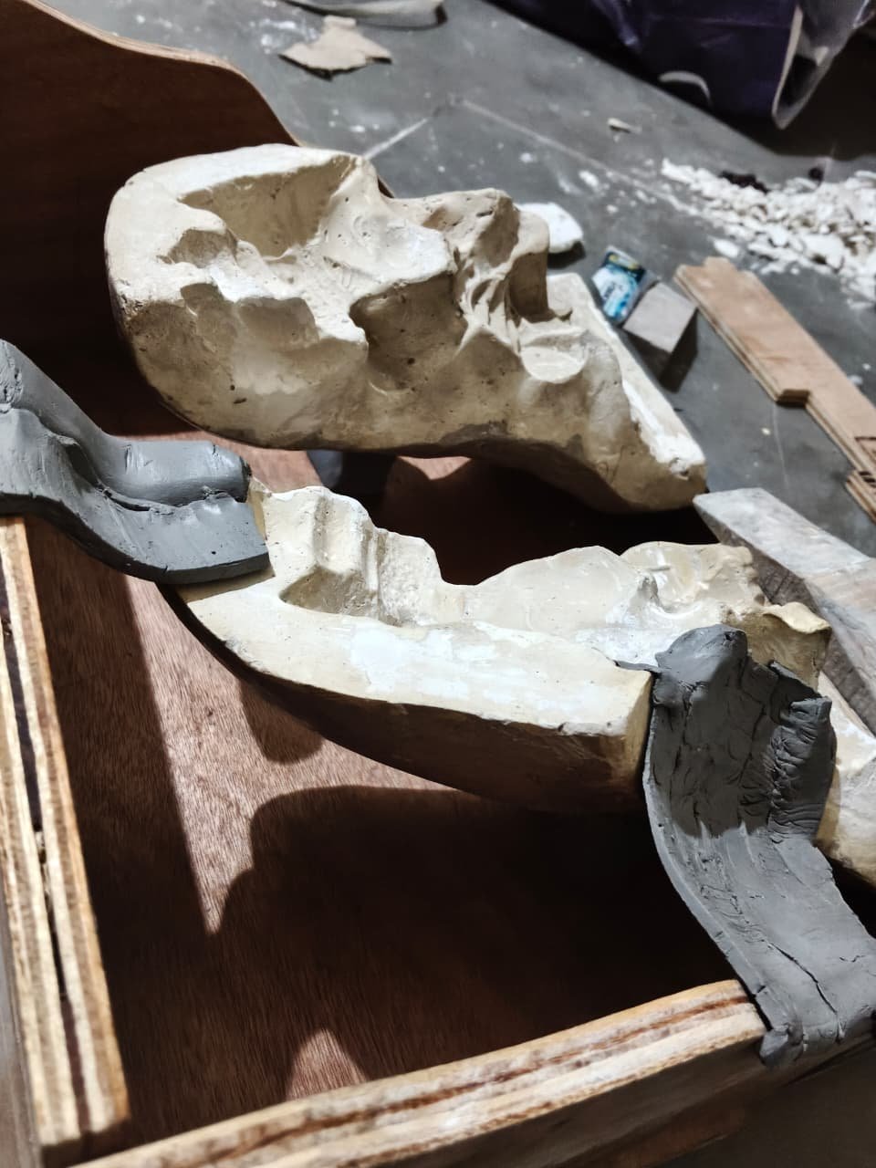
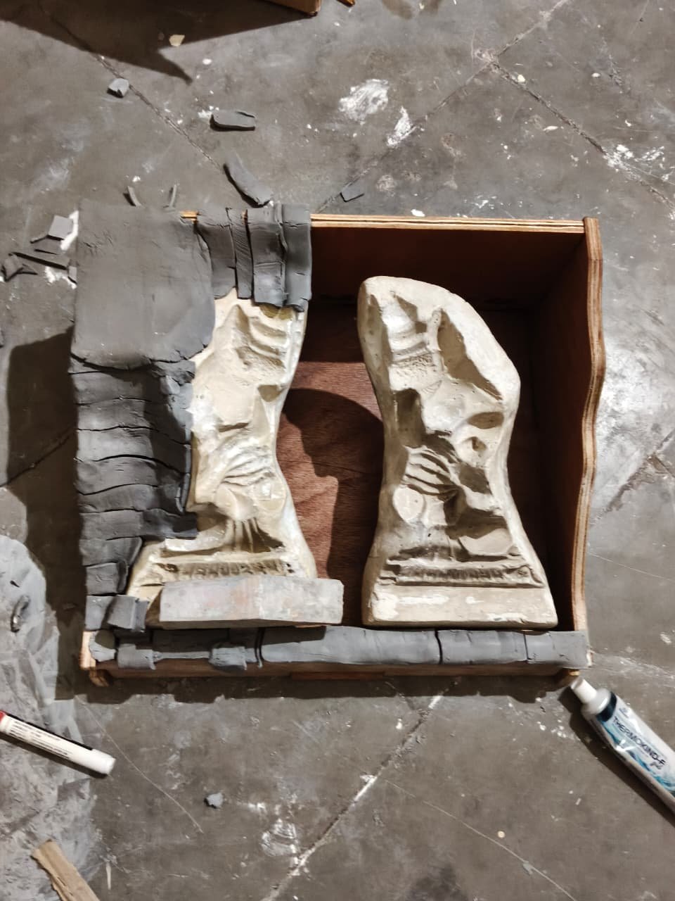
- first we made a stand out of clay itself to hold the existing mould at a place at an angle.
- next we started forming the barrier with the help of clay itself.
as i continue the was reaching toward failure. the clay was drying in the process. the time it was taking. and the pieces were falling. not properly holding toghether.
we stop her again. the thought might come that every time stoping in betweeen is not good. atleast trying it. it was not that it wont work it just took long. still the reason i was not moving ahead with those method. is putting time and effort in that to complete the way i thought before feels like just wanted to make it work. it would have work. if i just wanted to make it work. but the potential of other idea in the stuck situation. at this time brain it highly active to solve the problem. and the idea might come with better solution.
still we cloud have done and thought afterward. but just to complete it one go. i started exploring more ideas. to save efforts in wrong methods.
my ideology say there can be only one best solution to a problem. and doing that one should be the goal.
i talked to my guide. as we were talking we talked about mould making different approaches. and the idea came here was how sand in used for casting irons. it hold the shape. so later i started exploring the idea.
here the sand is can be shape into anything. flat, curvy, and it holds its shape very well.
it is not normal sand. it is bit moist. not dry. and not too much mosit too. and this practise is well know and can be mimic and copy easily at ground. no need of high tech. easy to do. know by ground worker.
day 7th of making mould.
on 7th of may, we started making our mould placeholder again. using new idea. using the sand .
the idea before was first make bottom mould. than gres it, and than make top mould by just pouring it. bsoc top mould can be easily made by pour when the bottom is done.
reason when bottom mould have it complete shape. the curve is already there. isolation is there and top part of top mould is flat too. so no need to wait just pour happen.
the major challenge was with bottom mould. now the thought is lets make top mould first. mean what we will do is make bottom mould with sand. than place the top mould walls and pour the pop. than flip it. remove the sand and use top mould as base and reverse the position and fill pop fully again.
the steps will be mentioned below properlt.
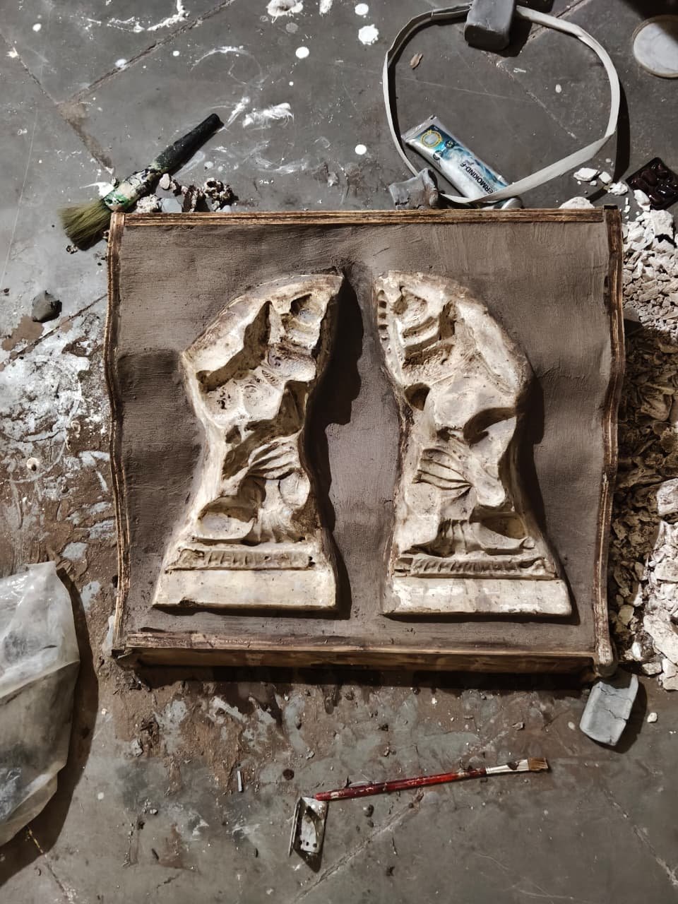
first fill the bottom with sand just like the pop ment to be fill the acutual shape. of the placeholder.
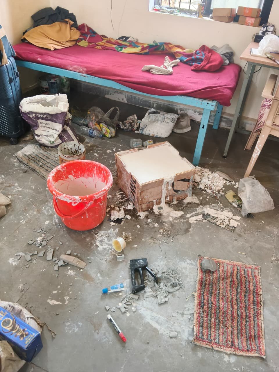
sec, place the top part of the container and than fill the pop to take the impression.
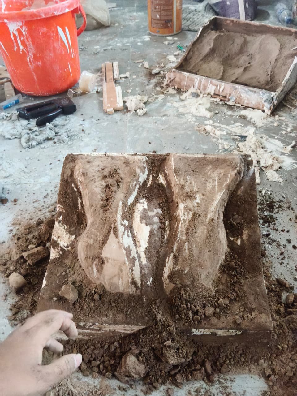
3rd, unmould after it set and clean it later.
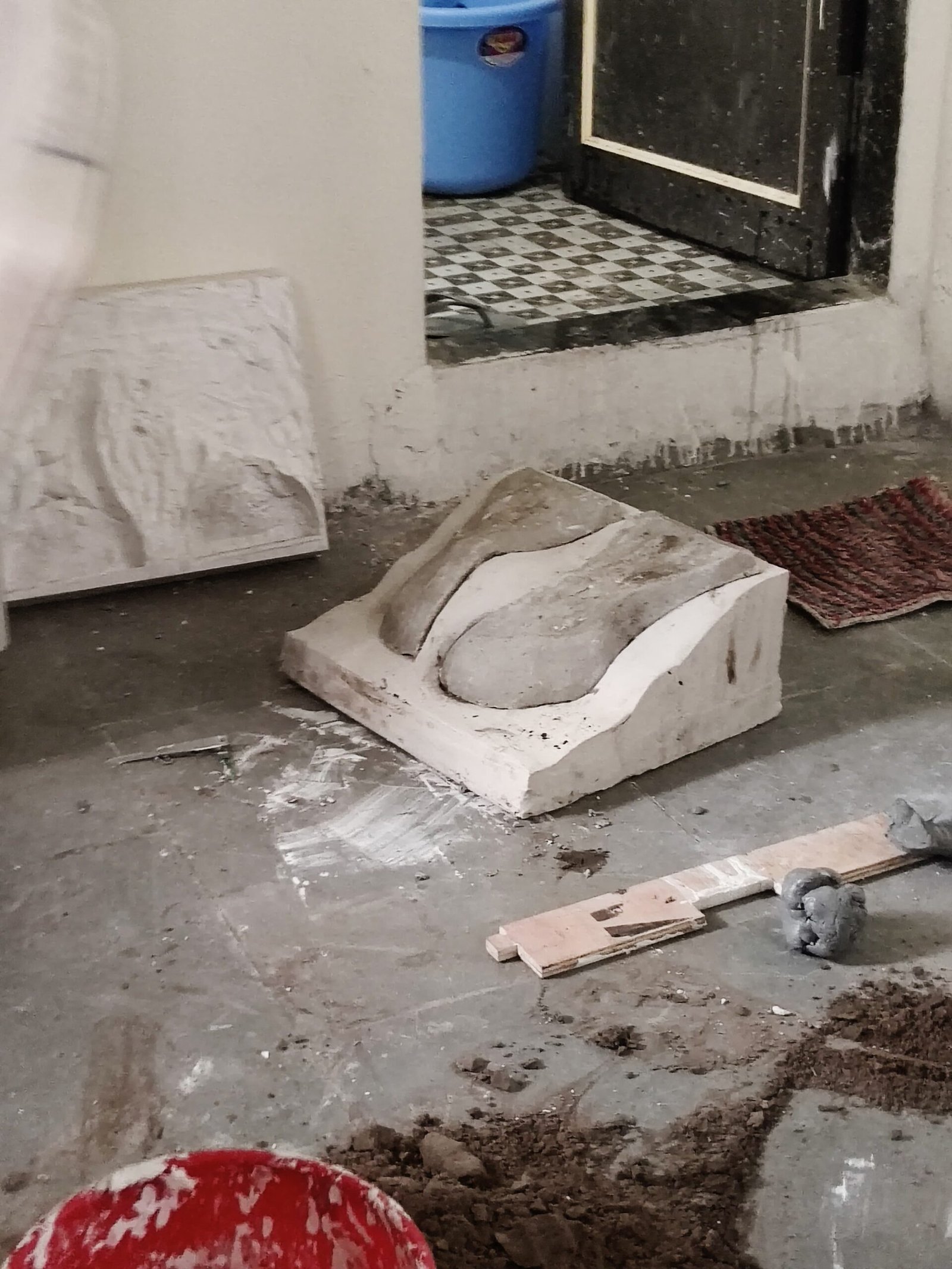
here we get the top part. and the existing mould is removable. so we can see the impression aswell.
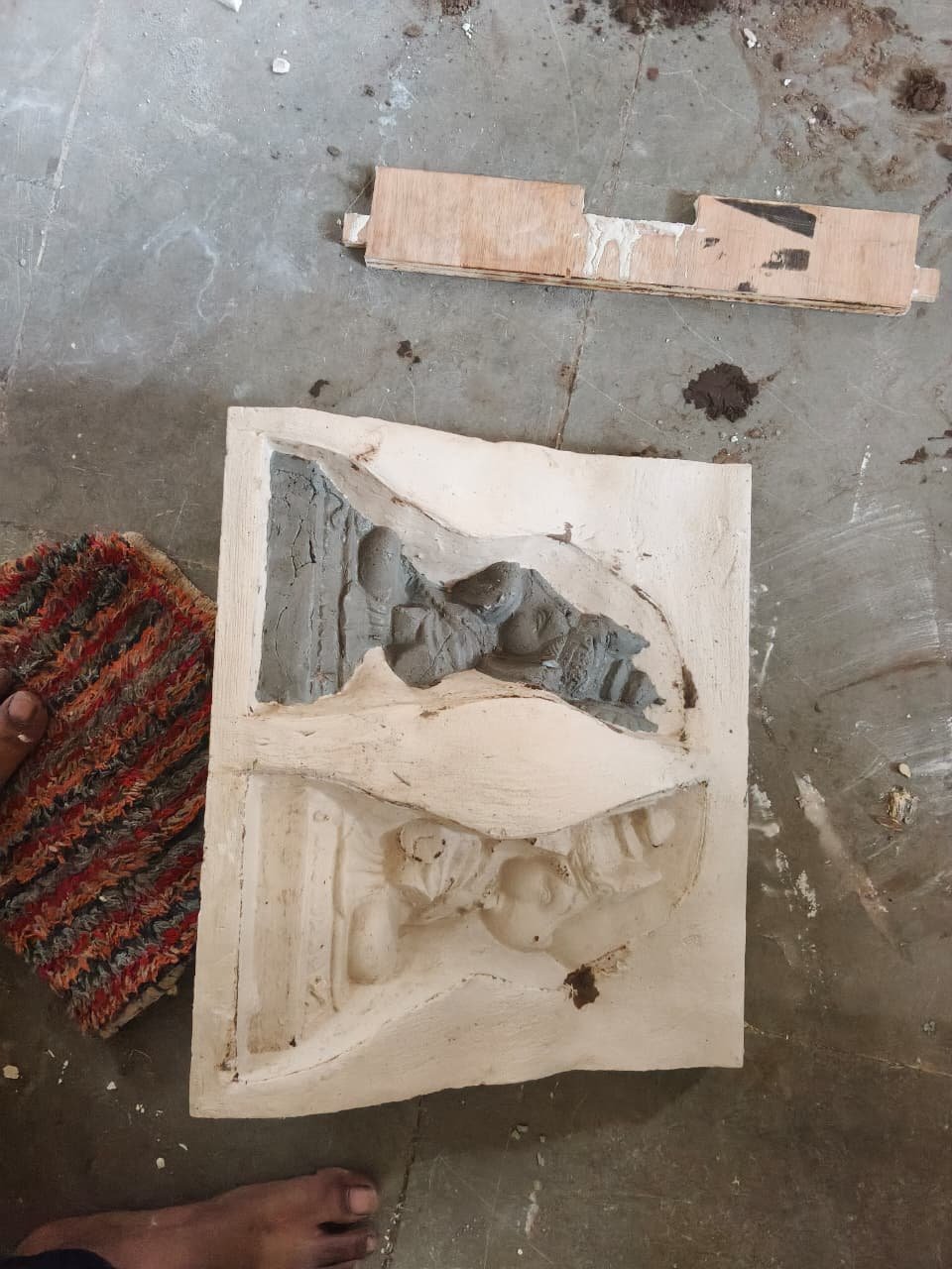
do the same process again. place the wall and pour the pop. to get bottom mould placeholder part.
and we will get both the part ready.
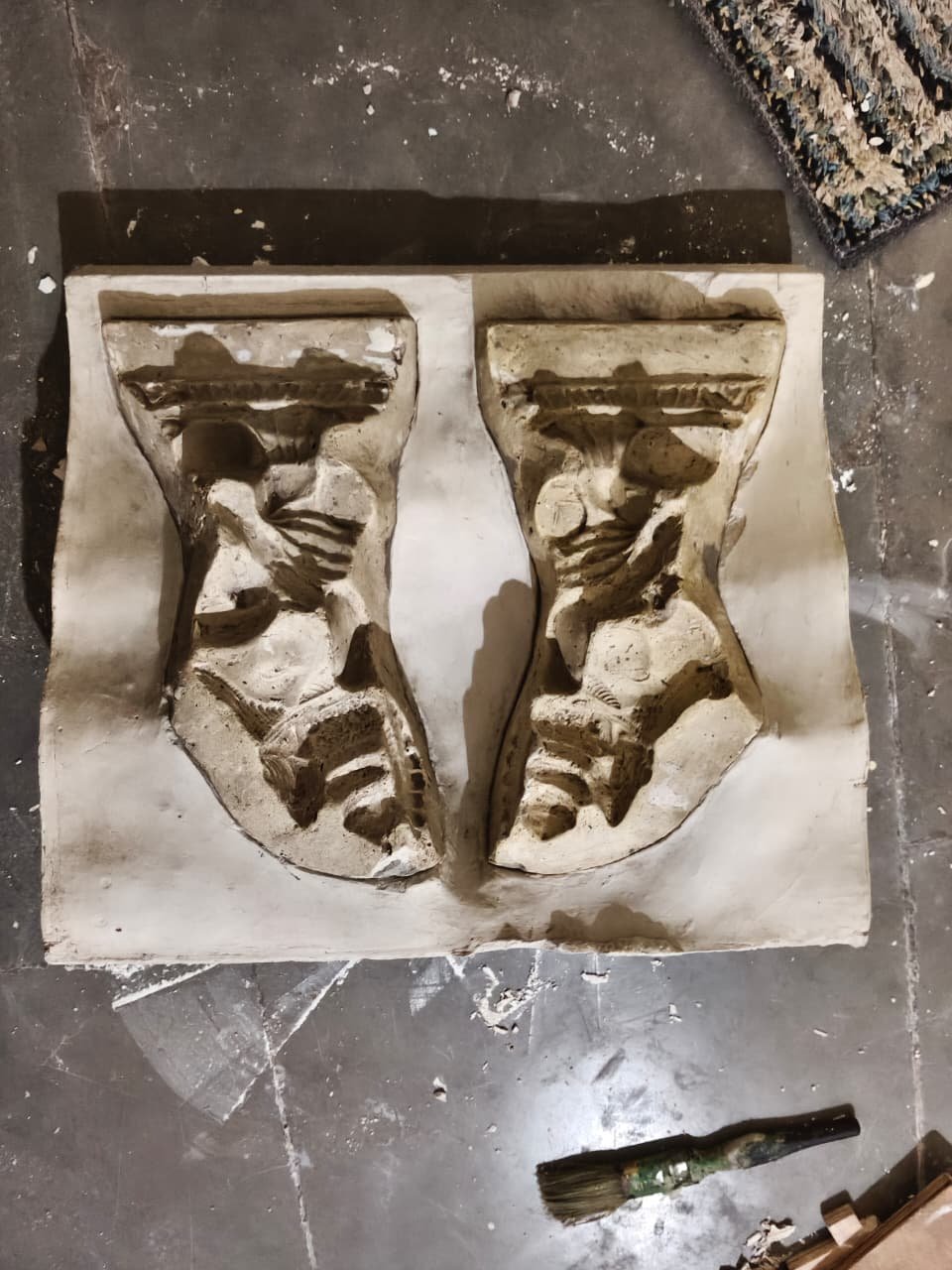
This is not the complete SOP. below i will be giving full steps and method below. with breif explaination as well.
Standard Operating Procedure (SOP): Split Mould Holder Fabrication
Process: mould place holder making
Objective: Cast matching top and bottom Plaster of Paris (PoP) mold holders around an existing master mold while establishing a precise, repeatable wall thickness for clay production.
1. Process Overview & Reasoning
This process creates a matching two-part mold holder system by using damp sand as a temporary support bed and Shadu clay as a precise offset spacer. First, the lower section of the existing master mold is set into a sand bed inside an interlocking wooden frame, and a uniform layer of Shadu clay is sculpted over it to define the exact wall thickness of the future pressed clay part. Next, the upper interlocking box walls are attached and PoP is poured to create the Top Mold Holder, capturing both the clay profile and the upper portion of the master mold. The modular puzzle-style container walls are then completely removed—allowing safe demolding without damaging delicate PoP edges. Finally, the cured Top Mold Holder (with the upper master mold half in place) is inverted, greased, re-framed with the lower container walls, and used directly as the base face to pour the Bottom Mold Holder around the remaining lower master mold.
-
Why set the master mold in sand to edge height? It creates a solid, temporary base matching the container’s curved rim height without needing to wait for a complex bottom PoP pour first.
-
Why add the Shadu clay layer before pouring? Without this clay layer, the top and bottom PoP holders would cast flush against each other with zero gap. The clay creates a temporary offset space that defines the exact thickness of the clay during production pressing.
-
Why use puzzle-style interlocking container walls? PoP features along angled and curved parting lines can chip if pulled straight out. Removing the walls laterally around the mold eliminates mechanical interference during demolding.
-
Why place the master mold sections in both halves? Capturing the top half of the master mold in Phase 3 and the bottom half in Phase 4 ensures that both the Top and Bottom PoP Mold Holders form complete, rigid structural seats for the actual production molds.
2. Materials & Equipment Required
-
Container Assembly: Modular, puzzle-interlocking wooden box (curved split-height side walls, removable end panels).
-
Master Components: Existing master mold (Top and Bottom sections), Shadu clay (for thickness modelling).
-
Base Materials: Fine molding sand (slightly dampened), Plaster of Paris (PoP), clean water.
-
Consumables: Release agent (grease/Vaseline or oil spray).
-
Tools: Sculpting/smoothing tools, spatula, scraper, soft brush, rubber mallet.
3. Step-by-Step Procedure
Phase 1: Sand Bed Setup & Master Mold Positioning
-
Step 1.1: Interlock and lock the bottom wooden frame panels together on a flat work surface.
-
Step 1.2: Place the lower section of the existing master mold into the center of the container.
-
Step 1.3: Fill the surrounding area with damp molding sand. Press sand underneath and around the master mold until it is firmly supported and its edge level sits flush with the curved rim height of the wooden container.
-
Step 1.4: Compact and smooth the exposed sand bed around the master mold perimeter using a scraper or trowel.
Phase 2: Clay Spacing Layer Application (Cavity Sizing)
-
Step 2.1: Apply a uniform layer of Shadu clay directly over the exposed upper surface of the master mold.
-
Step 2.2: Sculpt and smooth the clay surface to match the exact exterior shape and detail needed for the final Ganapati/clay part.
-
Step 2.3: Verify that the clay thickness is consistent throughout.
Cavity Logic: This exact clay layer creates the physical offset between the two holders. During actual production, this cavity volume will be filled with raw clay to form the part.
Phase 3: Top Holder Casting & Full Wall Disassembly
-
Step 3.1: Position the top half of the master mold directly onto the clay layer, ensuring proper alignment.
-
Step 3.2: Assemble and interlock the top wooden side panels onto the base frame to complete the upper box enclosure.
-
Step 3.3: Apply a thin, even layer of release agent over the exposed Shadu clay, upper master mold, and interior wooden walls.
-
Step 3.4: Mix PoP with water to a smooth consistency and pour it into the top container over the clay and mold assembly. Gently tap the wooden frame with a rubber mallet to vibrate out trapped air bubbles.
-
Step 3.5: Screed the exposed top surface flat using a straight edge and allow the PoP to set fully (20–30 minutes).
-
Step 3.6: Unlock and completely remove all interlocking puzzle wall panels from the container.
-
Step 3.7: Lift off the cured Top PoP Holder (which now holds the top half of the master mold), invert it, and peel away the temporary Shadu clay and damp sand. Wash or brush the impression face clean.
Phase 4: Bottom Holder Placement & Casting
-
Step 4.1: Place the cured Top PoP Holder flat-side down on the workbench so its clean, detailed impression face points upward.
-
Step 4.2: Position the remaining bottom half of the master mold onto its corresponding interface location on the Top Holder.
-
Step 4.3: Apply a generous layer of grease or release agent over the entire exposed PoP interface, bottom master mold details, and cavity features to prevent the new PoP from bonding.
-
Step 4.4: Re-assemble and interlock the lower wooden frame panels tightly around the cured Top Holder.
-
Step 4.5: Prepare a fresh batch of PoP slurry and pour it directly into the enclosure over the greased impression face and master mold half until the frame is completely filled.
-
Step 4.6: Level the top flat surface with a scraper and allow the bottom section to cure completely.
Phase 5: Final Disassembly & Seam Inspection
-
Step 5.1: Unlock and remove all interlocking wooden side panels from the cured block assembly.
-
Step 5.2: Gently split the Top and Bottom PoP Mold Holders apart along the greased parting seam.
-
Step 5.3: Clean away residual release agent or flash. Verify that both holder halves cleanly register their respective master mold components and that the internal cavity created by the Phase 2 clay spacer is uniform throughout.
4. Key Process Controls
-
Clay Thickness Uniformity: Ensure the Shadu clay layer applied in Phase 2 is uniform; variations directly cause thin or thick spots in pressed clay parts.
-
Complete Wall Removal: Always disassemble the interlocking puzzle walls horizontally before lifting cured PoP blocks to prevent chipping along angled box contours.
-
Total Greasing: Never pour fresh PoP in Phase 4 without verifying 100% release agent coverage on the cured top holder face and master mold surface, or both halves will permanently fuse.
press machine prototyping
As of now our mold place holder work is done. and now we can move ahead to press machine machenism.
This is the next important part of our prototyping. as we discussed and concluded that the mold press will work and have high chance of our concept to work. the test with mold was good and result promissing method. We were unble to press the mold completely due to less force. and not properly aligned.
For mold to properly aligned and get proper force we need to make press machine.our thought of without machine just mold and press with human force was wrong desicion. It was obvious that it wont work but we learn the reasons why it wont work. and what problem we have to solve with our press machine.
This learning will help us to design the perfect machenism for our mold press
understanding
After completing the mold placeholder tests, we validated that the core process—pressing clay into segmented molds—is viable and yields promising detail capture. However, the initial attempt to press the molds manually using direct human force revealed a critical operational bottleneck: we were unable to achieve full clay compression due to insufficient force output.
Realizing that manual pressing was unfeasible shifted our focus to machine-assisted pressing. Before jumping into specific mechanical linkages, we needed to thoroughly understand the structural, spatial, and force demands that our custom press machine must satisfy.
Key Requirements & Functional Demands
Unlike standard industrial metalworking or benchtop presses, our application introduces a unique set of geometry and ergonomic constraints:
+-----------------------------------------------------------------------+
|                         CUSTOM PRESS DEMANDS                          |
+-----------------------------------------------------------------------+
|  1. Large Working Envelope  |  Must accommodate wide, bulky mold      |
|                             |  holders without edge interference.     |
|-----------------------------+-----------------------------------------|
|  2. High Force Output       |  Must reliably deliver ~200 kgf load   |
|     (200 kgf)               |  to fully compact thick Shadu clay.    |
|-----------------------------+-----------------------------------------|
|  3. Quick-Change Mold       |  Needs modular mounting for all 4       |
|     Mounting                |  segmented mold pieces (Front/Back/L/R).|
+-----------------------------------------------------------------------+
-
Large Working Envelope & Clearance:
-
The Issue: Commercial shop presses or standard hydraulic arbor presses usually feature narrow rams designed for single-point pressing. Our mold placeholders are wide, bulky, and feature irregular curved parting lines.
-
The Requirement: The machine requires a spacious flat bed and a wide top platten to distribute force evenly across the entire surface of the mold placeholder.
-
-
High Force Generation (~200 kgf Output):
-
The Issue: Shadu clay has high resistance to plastic deformation, especially when filling deep, intricate features (like clothing folds or facial details on Ganapati idols). Manual effort fell far short of the necessary compaction pressure.
-
The Requirement: The mechanism must provide substantial mechanical advantage—converting reasonable human input effort into a sustained downward force of at least 200 kgf at the bottom of the stroke.
-
-
Modular Mounting & Ergonomic Workflow:
-
The Issue: The overall process requires pressing four separate mold segments (Front, Back, Left, Right) repeatedly.
-
The Requirement: The press bed and moving top ram must allow quick mounting, secure clamping, and easy clearing of the mold holders so an artisan can rapidly cycle through all four parts without tedious setup delays.
-
Researching Existing Pressing Concepts
To solve these specific challenges without over-engineering a costly or overly complex industrial machine, we explored various manual press mechanisms used across different craft and manufacturing domains:
-
Standard Benchtop Arbor Presses: Excellent mechanical advantage, but severely limited by throat depth and small pressing plates, making them unsuitable for wide molds.
-
Manual Bookbinding & Tile Presses: Offer large, flat pressing surfaces, but rely on slow threaded spindles that make high-volume, repeatable artisan production too tedious.
-
Flywheel / Flypresses & Toggle Lever Systems: Offer rapid downward movement paired with peak mechanical advantage at the very bottom of the stroke—ideal for pressing clay into precise impressions.
Framing the Prototyping Goals
With these parameters established, our prototyping goal for the machine phase became clear: Design a cost-effective, high-rigidity frame equipped with a force-multiplying mechanism that guarantees a high-force load over a spacious bed.
This led us directly into evaluating and comparing specific mechanisms—such as the Flywheel Screw Press and the Lever Linkage Press—to determine which approach best balances mechanical advantage, ease of fabrication, and workshop ergonomics.
thinking
(20-may-2026 to 20-june-2026)
In the previous section, We understood what exact problem we will be solving with our press machine. We made discousion on the multiple machenism which solve our alignment issue and froce issue.
DISCUSSED MECHANISMS
we discussed 3 type of machenism or method here while discussing. and this mechenism desigbn are completly different but solve the same problem. below are those deisgn and concept behind that.
The flywheel press machnism
The mechanism you described with the top wheel, screw jack, and return spring is widely known as a Flypress or a Flywheel Screw Press.
-
How it works: You give the heavy wheel at the top a quick push. The wheel acts as a flywheel, storing your quick effort as rotational kinetic energy. As it spins, the heavy screw thread forces the ram downward.
-
The Power Multiplier: The magic happens at impact. The massive angular momentum of the spinning wheel is stopped instantly when it hits the bottom bed, converting that energy into a massive burst of downward linear force (mechanical advantage).
-
The Return: The spring at the bottom compresses during the downward stroke, and as soon as the impact is over, it rebounds and pushes the screw back up to its starting position automatically.
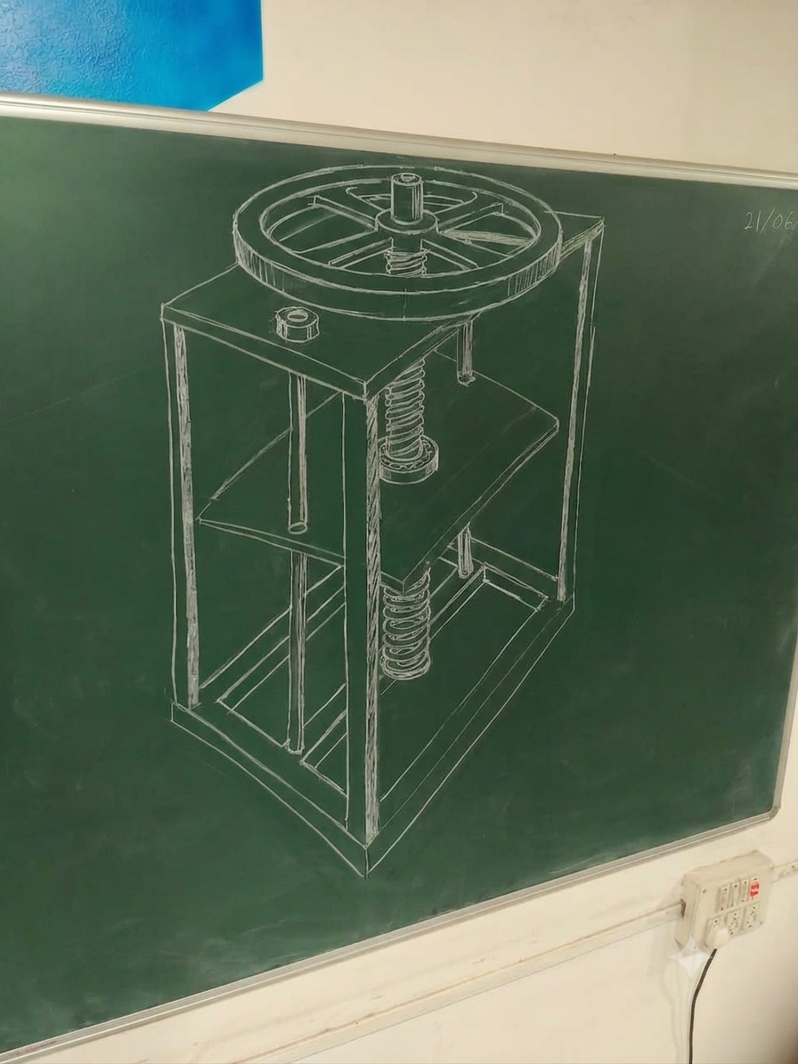
2. The Lever Press Mechanism
This mechanism uses a manual lever handle to convert straightforward rotational pulling force into direct, high-pressure linear downward movement.
-
The Power Multiplier: Force multiplication is achieved purely through the physics of a leverage arm. The physical length of the handle acts as the force multiplier: a longer handle allows a person to easily generate massive downward force with very little manual effort.
-
Force Characteristics: This setup provides direct, predictable, and highly controllable force throughout the entire stroke. By keeping the design focused on basic mechanical leverage, it remains incredibly robust, straightforward to operate, and requires minimal maintenance.
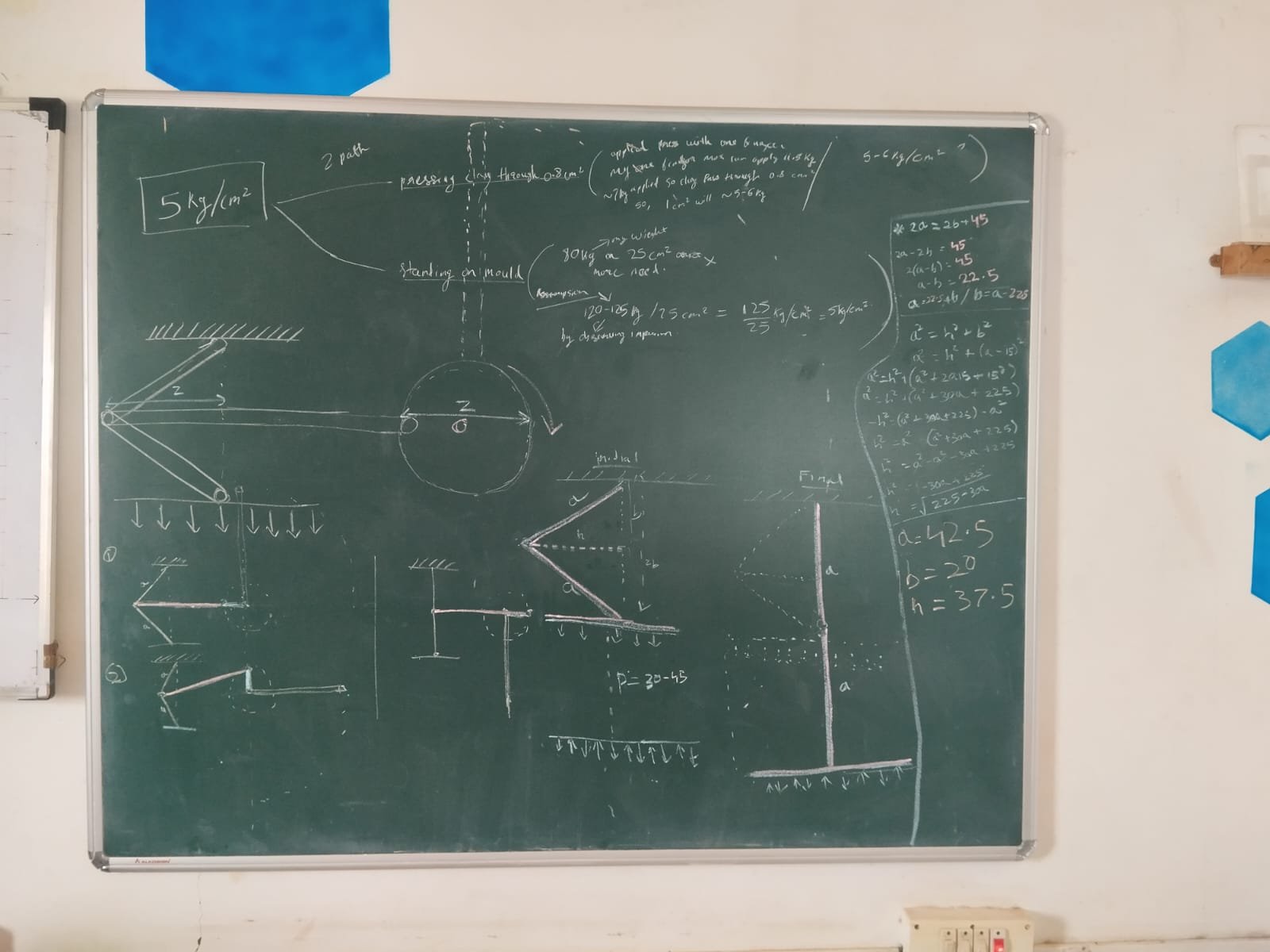
Following our review of potential mechanisms with our project guide and team members, we officially selected the Manual Lever Press Mechanism as our design direction. While the Flywheel Screw Press is capable of producing significant force via dynamic momentum, its implementation introduces substantial engineering overhead. A screw-jack design requires multiple full rotations to achieve a single stroke, and fabricating a dynamic flywheel system with balanced weight distribution, lead-screw threads, and rebound spring dynamics adds unnecessary mechanical complexity.
In contrast, the Lever Press Mechanism operates on fundamental principles of statics and mechanical advantage: Torque (torque = F . r) and Linear Force Multiplication F2 = F1. (L1/L2). By extending the input leverage arm L1 relative to the short output pivot distance L2, a modest manual pulling force is directly amplified into a massive downward load without requiring high-rpm rotational movement or complex machining.
The decision came down to five core engineering parameters:
+-------------------------------------------------------------------------+
|                  MECHANISM EVALUATION PARAMETERS                        |
+-------------------------------------------------------------------------+
|  1. Fabrication Simplicity  |  Relies on standard links, shafts, and    |
|                             |  pivot pins rather than high-precision    |
|                             |  threaded lead screws and balanced wheels.|
|-----------------------------+-------------------------------------------|
|  2. Operational Speed       |  Single-stroke lever motion vs. multiple  |
|                             |  spindle rotations per cycle.             |
|-----------------------------+-------------------------------------------|
|  3. Deterministic Physics   |  Direct force calculation based on simple |
|                             |  linkage ratios rather than complex kinetic|
|                             |  energy/momentum transfer calculations.  |
|-----------------------------+-------------------------------------------|
|  4. Precise Force Control   |  Tactile feedback allows the artisan to   |
|                             |  modulate pressure directly mid-stroke.   |
|-----------------------------+-------------------------------------------|
|  5. Low Maintenance         |  Fewer wearing surfaces, zero dynamic     |
|                             |  rebound alignment issues.                |
+-------------------------------------------------------------------------+
Ultimately, the lever linkage offers a straightforward, robust, and easily manufacturable solution. It meets our 200 kgf force requirement with minimal calculation overhead and seamlessly fits into an artisan’s workshop environment without requiring complex user adaptation.
making fabricating
(23-June-2026 to 18-July-2026)
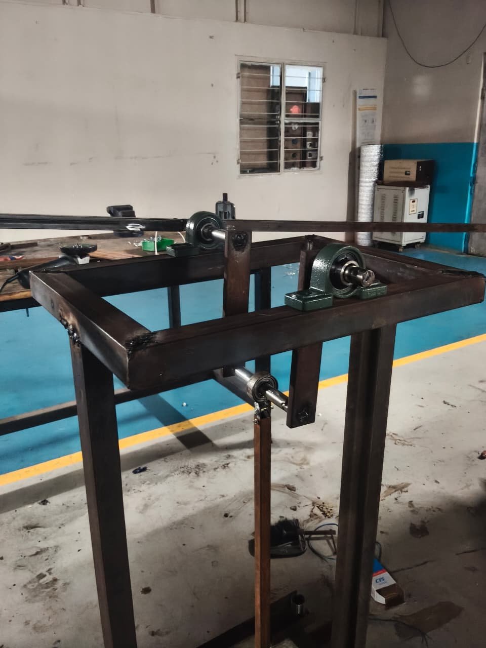
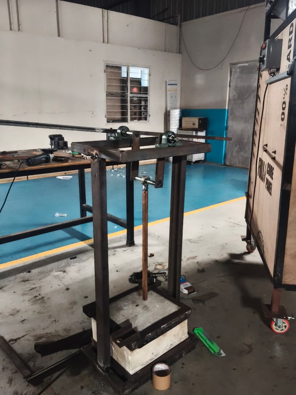
Having confirmed our press mechanism concept, we moved directly into preparing for physical fabrication. With the mechanism design decided, the next step was to conduct market research, source our materials, and finalize our build details before starting work on the shop floor.
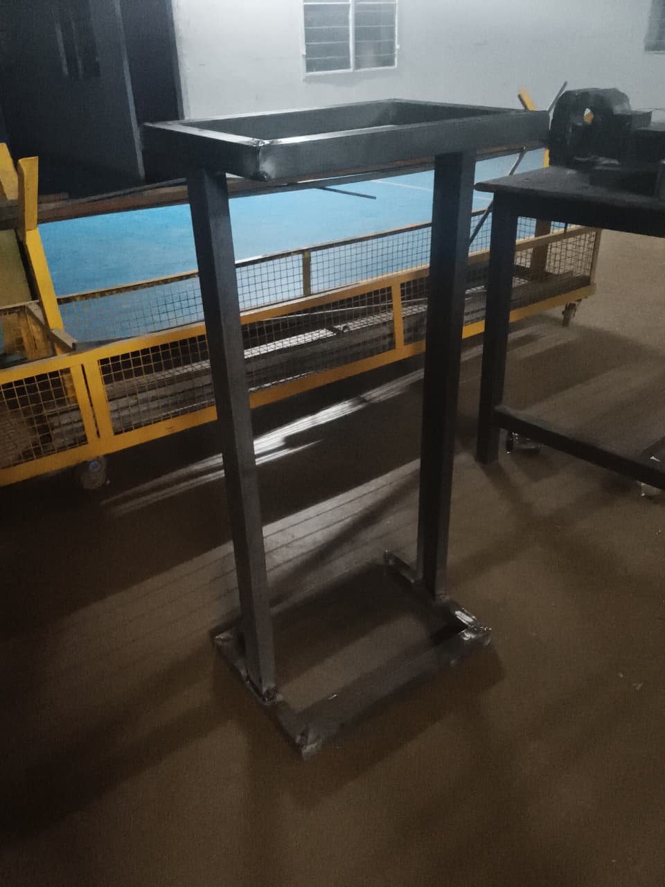
Instead of strictly sticking to a rigid CAD drawing, we adapted our design based on what was immediately available in our workshop and the local market. The core mechanical concept remained unchanged, but the physical implementation was tailored to fit local stock and off-the-shelf components.
1. Material & Component Selection
Our material choices were driven by cost, structural requirements, and local market availability:
-
Guide System: Stainless Steel (SS) Pipes (vs. Solid Rods)
We chose standard SS pipes over solid steel ground rods for the vertical guide assembly. SS pipes provided a sufficiently smooth, rust-free surface for vertical travel while being significantly lower in cost than solid ground rods.
-
Main Frame: Mild Steel (MS) Box Pipes
We selected MS square box pipes for the main structural frame. MS box sections provided high rigidity against bending, were easy to cut and weld with our workshop tools, and served as a strong base for the machine.
-
Bearings & Motion Hardware
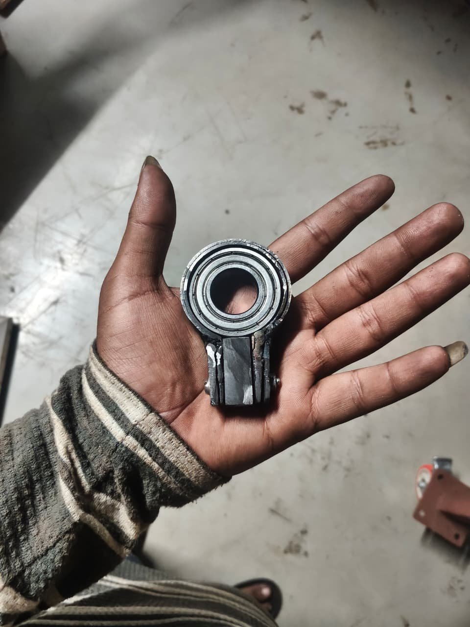
We identified mounted/flanged bearings and linear bush bearings to handle the sliding top plate and pivot linkage movements, ensuring smooth motion along the guide axes.
2. Sourcing Strategy & Workshop Inventory
To streamline our build, we divided our material requirements into targeted market purchases and in-house workshop stock:
-
Targeted Purchases (Key Market Items):
Our primary purchasing focus was limited strictly to essential motion hardware—specifically the smooth SS pipes and bearings (mounted bearings and linear bushings).
-
Workshop Stock & Custom Fabrication:
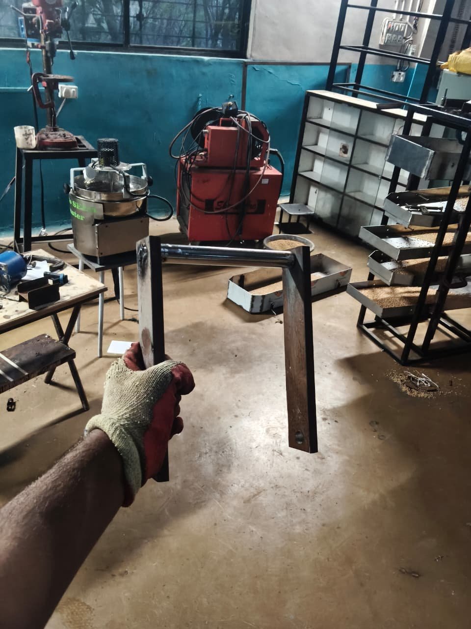
Most remaining structural parts—including frame reinforcement plates, lever linkages, mounting brackets, and fasteners—were already available in the workshop or could be custom-cut and welded directly from existing stock.
Next Step: Sourcing & Assembly
With our critical purchase list focused solely on the smooth SS pipes and bearings, we headed out to procure the hardware and prepare for physical fabrication on the shop floor.
impression test
July 18 2026 – July 23 2026
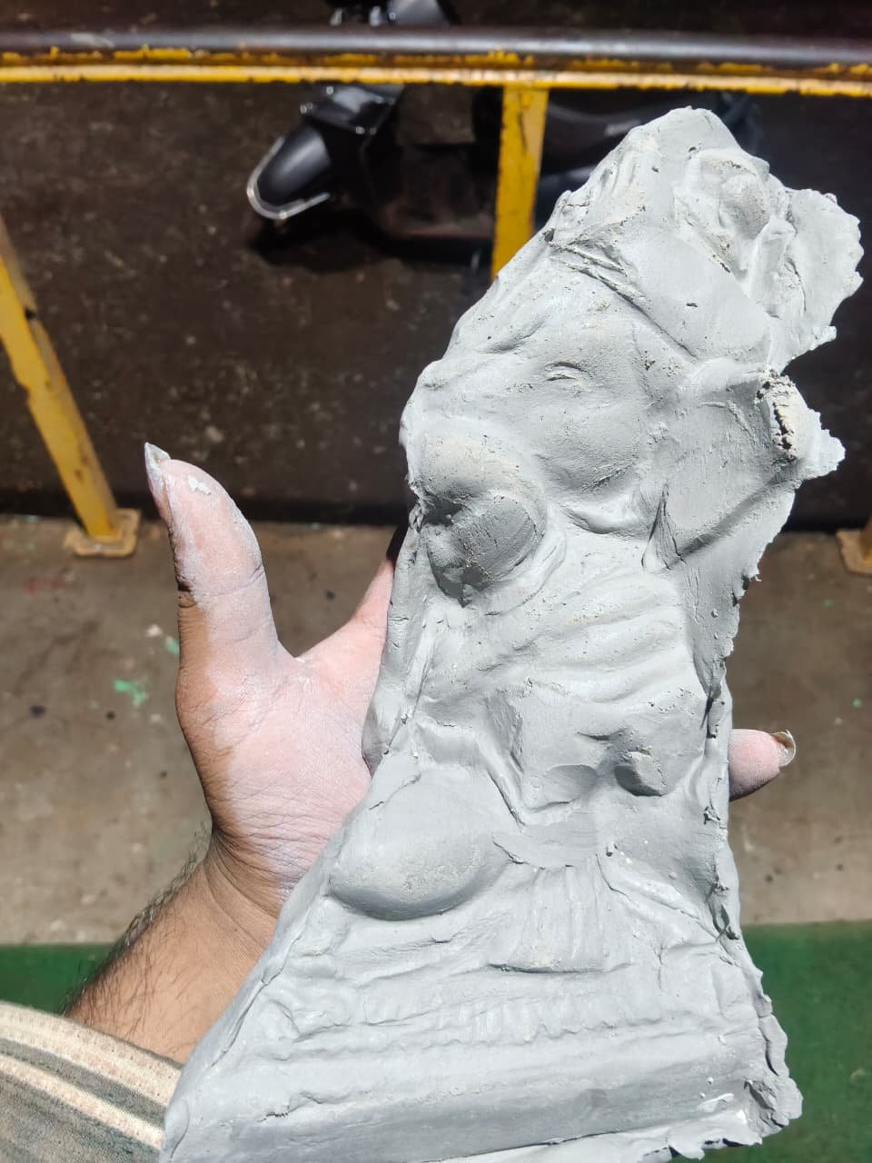
Physical assembly of the prototype was completed on July 17 following a fabrication period that began on June 25. Although assembly was achieved, operational testing revealed critical mechanical failures. Through systematic evaluation, the team identified the root causes of these failures and extracted key engineering lessons.`
2. Mechanical Failures & Root Cause Analysis
-
Guide Rod Instability: Loose-fitting guide rods led to erratic, jerky, and unconstrained movement along the vertical travel axis.
-
Linkage Geometry & Path Slippage: Improper fabrication and misalignment of the connecting rods caused trajectory failure under downward pressure. Instead of driving the mold downward, the mechanism skipped its intended path, reversing its angle and jumping to the opposite side.
-
Root Cause: The mechanical failures were primarily driven by sub-standard fabrication quality, insufficient shop-floor skill execution, and improper material selection.
3. Baseline Testing & Temporary Adaptations
To evaluate the core mechanism despite structural defects, targeted temporary workarounds were applied:
-
Operational Adjustments: Clearances around all four bearings were intentionally loosened. This added play allowed the bearings to adjust dynamically under tilt, overcoming binding friction so the top mold could move freely enough for basic functional testing.
-
Strategic Consultation: In a review regarding a potential full rebuild using newly gained insights, Dixit Sir advised against starting from scratch. The directive was to adapt the current prototype just enough to assess the viability of the pressing concept itself.
-
Testing Observations:
-
Force transfer failed as downward force could not be effectively transmitted due to connecting rod slippage.
-
Structural requirements became evident: generating the targeted 200 kgf force requires significantly higher structural rigidity across the linkages, handle, shaft, lever, and pivot joints to prevent flexing and slippage under load.
-
Team debrief & Core Mindset Shift
After testing, the whole group (DIC members, Shreyash, and Dixit Sir) sat down to map out the next phase.
-
The Engineering Trap: My initial impulse, along with the DIC team, was to jump straight into fixing mechanical bugs—tightening up tolerances, re-welding joints, and perfecting the frame.
-
The Real Priority: Dixit Sir and Shreyash flipped our perspective. The true objective isn’t delivering a flawless machine right now; it’s proving whether pressing clay can yield sharp, high-detail impressions. Getting bogged down in mechanical perfection was distracting us from validating the actual core concept.
Testing for impression
so, i started collecting and finding dead weighta