Assignment 1.Smart Dust Bin with Ultrasonic Sensor
We can make smart dustbin at home using only 5 or 6 items.
In this prototype project, I use Arduino Uno, ultrasonic sensor, jumper wire and servo motor.

Components
- Arduino uno,
- ultrasonic sensor,
- servo motor,
- jumper wire
- led,
First we create the code in Arduino Uno then we connect the servo motor
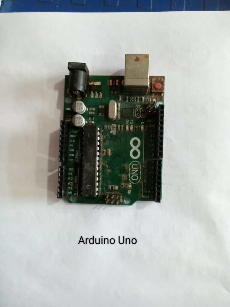
Step 1: Arduino Uno

Arduino Uno is an open-source microcontroller board based on the ATmega328P processor. There are 14 digital I/O pins, 6 analog inputs, a USB connection, a power jack, an ICSP header, and a reset button. To get started, simply plug it into a computer with a USB cable or power it with an adapter.
Hardware Structure of Arduino Uno
microcontroller,14 digital pins , 6 analog pins ,power supply electrical jack,usb port,reset button
Microcontroller: The microcontroller is the central processing unit of the Arduino Uno.
Digital Pins: There are 14 digital pins on Arduino Uno which are connected to components like LED, LCD etc.
Analog Pins: There are 6 analog pins on the Uno. These pins are commonly used to connect sensors as all sensors usually have analog values. Most of the input components are connected here.
Power Supply: The power supply pins I are GND, 3.3V, 5V are used to connect the sensors as all sensors usually have analog values. Most of the input components are connected.
Power Jack: The Uno board can be powered both via an external supply and a USB cable.
USB Port: This port is for programming the function board or uploading the program. The program is uploaded to the board with the help of Arduino IDE and USB cable.
Reset Button: It is used to restart the uploaded program.
Step 2: Servo Motor Connection

Servo motor wiring :
Connect the yellow pin (signal pin) to the Arduino digital pin no. 9
Connect the servo +Vcc pin to the Arduino +5V pin.
Connect the servo GND pin to the Arduino GND pin.
After this, connect the ultrasonic sensor to Arduino Uno and enter the code in Arduino Uno and edit the distance of the sensor.
step 3:ultrasonic sensor

Take the ultrasonic sensor connect sensor TRIG pin to Arduino pin no. 2.
Connect the sensor echo pin to the Arduino pin no. 3.
Connect the sensor +Vcc pin to the Arduino +5V pin.
Connect the sensor GND pin to the Arduino GND pin.
Code :-
#include <Servo.h>
Servo servo1;
int led=4;
int trig=5;
int echo=6;
int servo1_pin=9;
int duration=0,dist=0;
void setup()
{
Serial.begin(9600);
pinMode(led,OUTPUT);
pinMode(trig,OUTPUT);
pinMode(echo,INPUT);
servo1.attach(servo1_pin)
servo1.write(90);
}
void loop()
{
digitalWrite(trig, HIGH);
delayMicroseconds(10);
digitalWrite(trig, LOW);
pinMode(echo, INPUT);
duration = pulseIn(echo, HIGH);
dist = (duration*0.034) / 2; //obtain distance
if(dist<20)
{
Serial.println(“Dustbin Open”);
digitalWrite(led,HIGH);
servo1.write(90);
delay(10000);
}
else
{
Serial.println(“Chocolate Closed”);
digitalWrite(led,LOW);
servo1.write(0);
delay(500);
}
After uploading the code, I put a LED in the circuit and observed that whenever we go near the sensor, the led turns on and automatically turns off after 10 seconds. Same for the servo motor that rotates 180° and automatically comes back to its initial position after some time.
Step 4: Circuit Diagram


Step 5 : Prototype video
Assignment 2. Automatic Light Controller Circuit Using LDR and Relay

Going to make a simple automatic street light circuit using LDR and relay, which will switch on and off the light bulb depending on the surrounding light. This circuit is quite simple and can be made with transistors and LDR.
Step 1 : Components:
- transistor BC547
- LDR (Light Dependent Resistor)
- Riley
- resistor 1k
- 10k potentiometer
- connecting jumper wires
- bread board
- 1n4007 diode

Step 2 : LDR ( Light Dependent Resistor)

LDR stands for Light Dependent Resistor and its resistivity varies with incident electromagnetic radiations, so its resistivity is a function of incident electromagnetic radiation or light. Other names for LDR are photoresistor, photoconductor, photocell and photo conducting cell
LDR is made of high resistance semiconductor material like silicon or germanium. This is a light-sensitive device, so this resistor has different resistance values during day and night
Step 3 : Relay

- Relay Contact Current Capacity at DC5V: 10A
- one normally closed contact and one normally open contact
- triode drive, boost relay coil
- high impedance controller pin
- Pull-down circuit to avoid malfunction
- power supply indicator lamp
- control indicator lamp
- Indicator for relay output status
- Various appliances and other devices can be controlled with large current.
Step 4 : Circuit Diagram


Step 5 : Prototype video

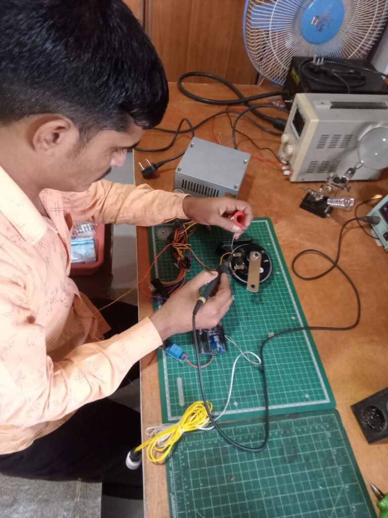
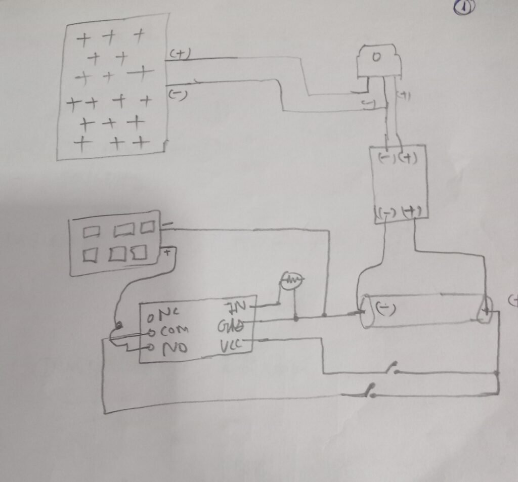
Assignment 3.Water level indicator with float sensor
Component:-
Arduino Uno
float sensor
speaker (12v)
SMPS (12V 14A)
relay (5v)
Float sensor
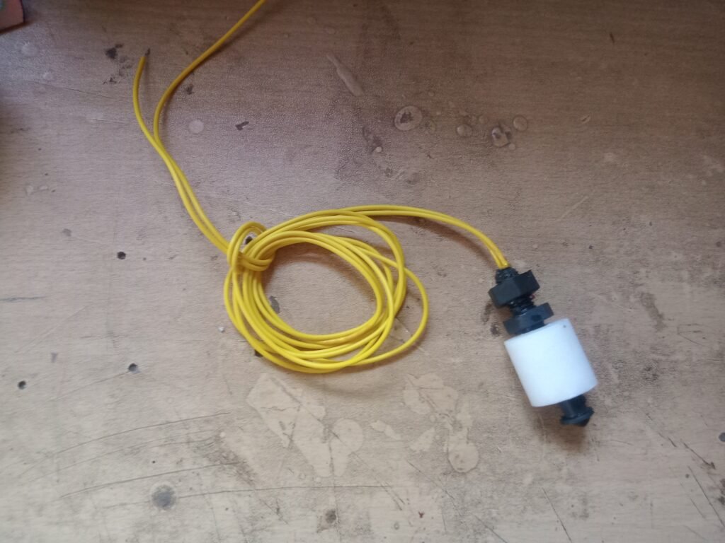
A float switch is a device used to sense the level of liquid within a tank, it may actuate a pump, an indicator, an alarm or other device.
A float switch is a device used to sense the level of liquid within a tank. The switch may actuate a pump, an indicator, an alarm or other device.
Examples of use : Hydroponics, Saltwater Tanks, Freshwater Tanks, Gardening, Aquariums for Power Head Control, Pet Bowls, Fish Tanks, Filtration, Heating, Pumps, Ponds, Basement Alarms, Boats, Air Condition Drain Pans, Pressure Washers, carpet cleaning machine, reef aquariums, fluid controls, ice machines, coffee pots, marine, automotive, automobiles, tropical fish tanks, evaporator coils, condensation lines, relays …
It can easily be converted from normally open to normally closed by reversing the float.
Arduino UNO
Arduino UNO is based on an ATmega328P microcontroller. It is easy to use as compared to other boards, such as Arduino Mega Board, etc. The board contains digital and analog input/output pins (I/O), shields, and other circuits.
Arduino UNO
Power LED Indicator – The status of the LED shows that the power is active. When the power is off, the LED will not light up.
Digital I/O Pin – The value of a digital pin is HIGH or LOW. Pins numbered D0 to D13 are digital pins.
Reset Button – This is used to add a reset button to the connection.
USB – This allows the board to be connected to a computer. This is essential for programming the Arduino UNO board.
Voltage Regulator – The voltage regulator converts the input voltage to 5V.
GND – Ground pin. The ground pin acts as the pin with zero voltage.
Vin – This is the input voltage.
Analog Pins – The pins numbered from A0 to A5 are the analog pins. The function of the analog pin is to read the analog sensor used in the connection. It can also act as a GPIO (General Purpose Input Output) pin.
Relay

1 Channel 5V Relay Board Module for Arduino PIC AVR DSP ARM. A wide range of microcontrollers like Arduino, AVR, PIC, ARM etc can control it.
Each requires 15mA – 20mA driver current and is equipped with a high current relay: DC 5V / 10A, AC 250V / 10A
SMPS:-

Power supply circuit plays a vital role in every electrical and electronic circuit from owl circuit to supply power to computer and various machines. The full name of SMPS is Switch-Mode Power Supply. SMPS is defined in simple language when the power requirement comes in the form of a switch. In which electrical energy is converted from one form to another with essential properties called SMPS.
In this type of SMPS, the input supply is AC and in the output we get DC supply. Rectifiers and filters are used to convert this AC power to DC. This uncontrollable DC voltage is fed to the affected power factor correction circuit. This is because there is a low current pulse inside the rectifier around the peak of the voltage.
Speaker (12V) :-
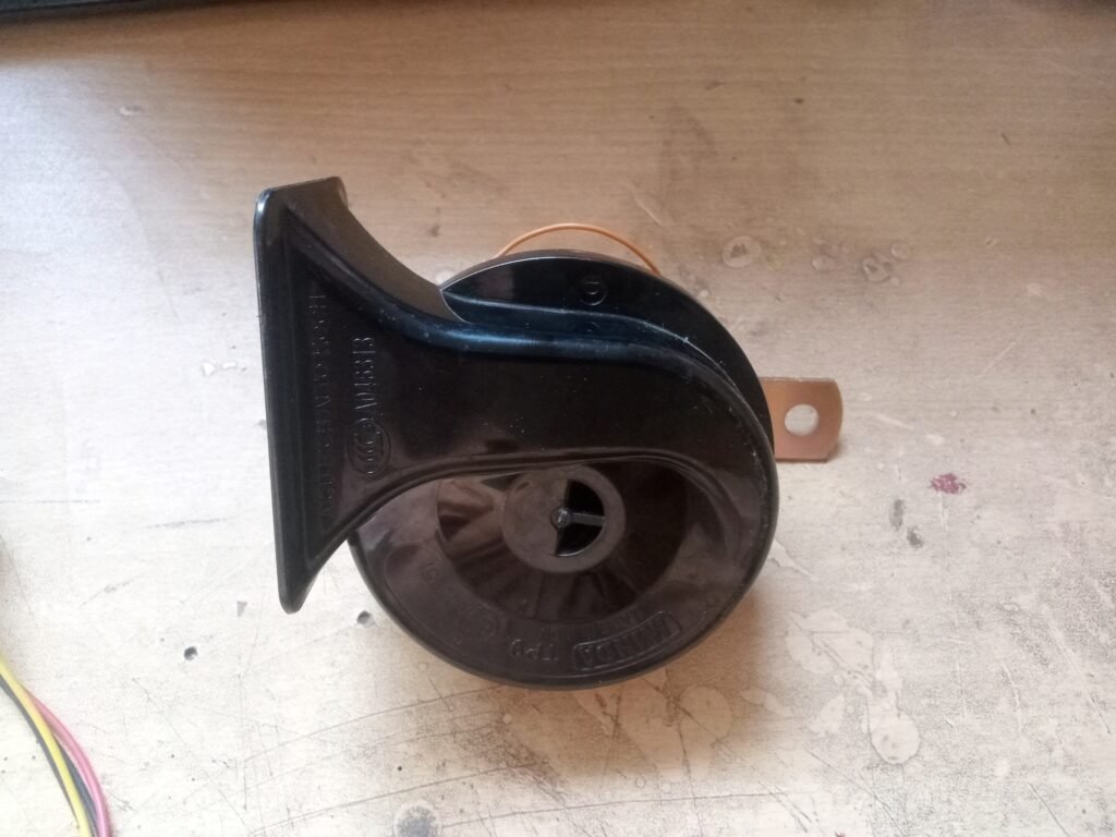
12v 3ah speaker is used for this project. The reason for installing this speaker is that when the water tank is full, its loud sound can be heard by everyone.
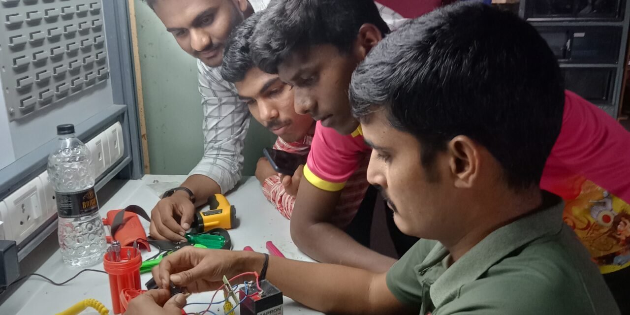
Steps :
- drawing the diagram
- finding the components that are needed
- read their datasheet
- soldering electronic components

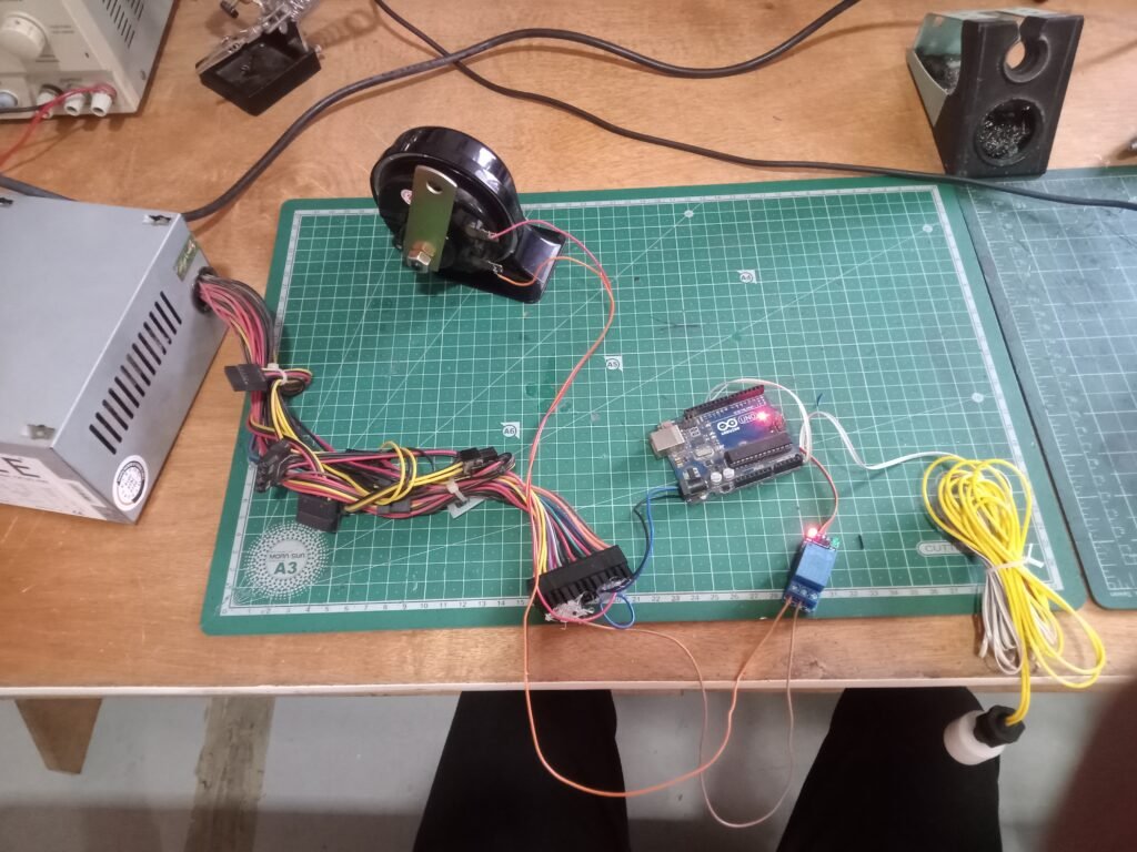
Circuit diagram :-

Arduino connecting pins
5v relay pin 5v
Gnd Relay Pin Gnd
pin9 relay signal pin
pin 11 float sensor (+)
Gnd float sensor (-)
relay com pin speaker
Relay NC Pin S MPS (-)
SMPS(+) speaker
Connect each component as shown in the picture and upload the code to Arduino.
Upload the code to Arduino.
#define relay 9
#define FS 11
int senstate;
bool x;
void setup() {
Serial.begin(9600);
// initialize digital pin 8 as an output.
pinMode(relay, OUTPUT);
pinMode(FS, INPUT_PULLUP);
digitalWrite(relay, HIGH);
x=false;
}
void loop() {
senstate = digitalRead(FS);
if (senstate == 1)
{
if (x)
{
digitalWrite(relay, HIGH);
delay(500);
digitalWrite(relay, LOW);
delay(1000);
digitalWrite(relay, HIGH);
delay(500);
digitalWrite(relay, LOW);
delay(500);
digitalWrite(relay, HIGH);
delay(500);
digitalWrite(relay, LOW);
delay(500);
digitalWrite(relay, HIGH);
delay(500);
digitalWrite(relay, LOW);
delay(500);
digitalWrite(relay, HIGH);
x = false;
Serial.println(“STEP ONE DONE”);
}
}
else if (senstate == 0)
{
if (!x)
{
digitalWrite(relay, HIGH);
x = true;
Serial.println(“STEP TWO DONE”);
}
}
delay(1000);
}
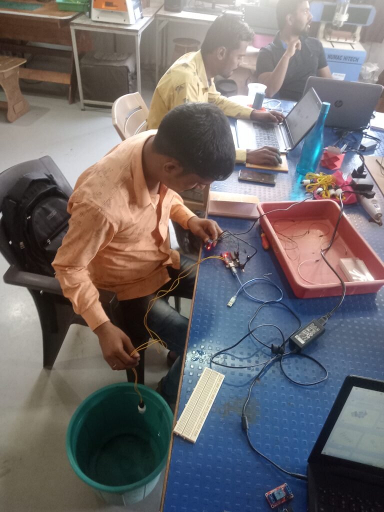
Then I tested my code and a location was selected for installation.
To install the safety box, the box was drilled in the wall and then the electric switch and socket were installed and then I checked by running the code.
After installing this, trouble shooting was happening, so that too was checked and rectified.
Making the cover for the control unit uses the junction box and installs the setup. Swim deep in the water tank.


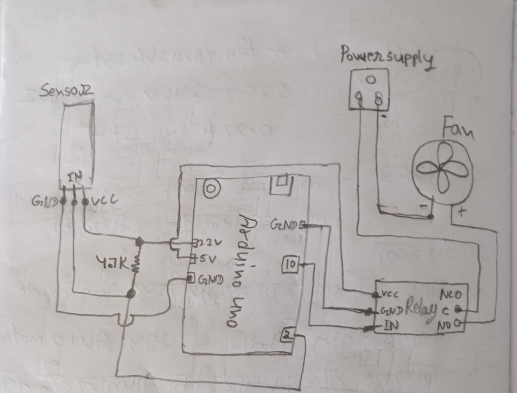
Assignment 4.DS18B20 temperature sensor
Components
- Arduino Uno
- 4.7k Resistance
- DS18B20 temperature sensor
- Relay 5v DC
- Exit fan 220v-240v AC
Arduino UNO


DS18B20 temperature sensor
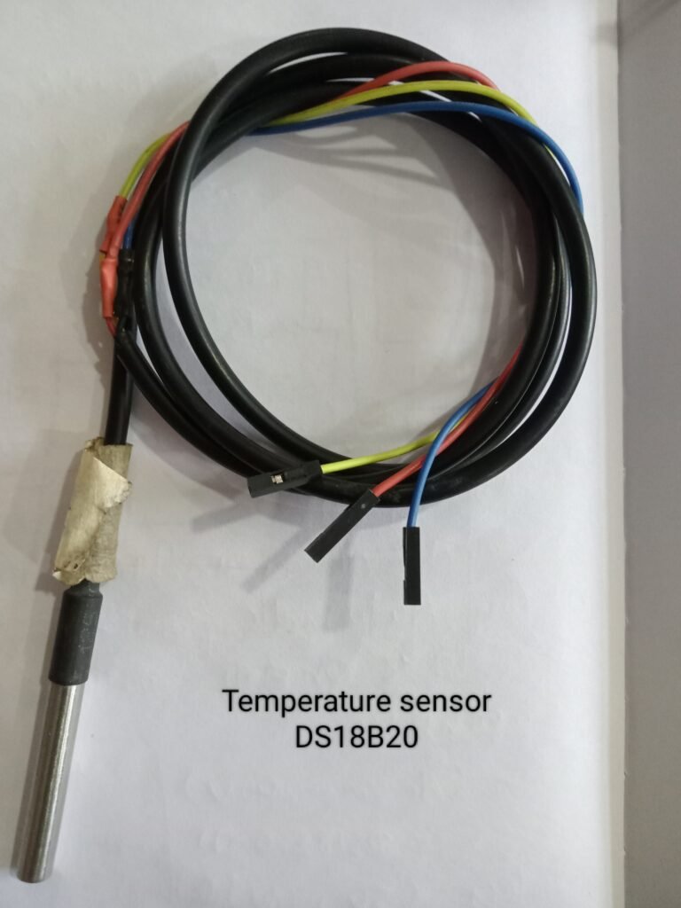
The DS18B20 temperature sensor is cool and doesn’t require any external components to function. Its temperature range is -55°C to +125°C
The sensor operates on a 3V to 5.5V power supply and draws only 1mA during active temperature conversion.
Specification :
Power Supply 3V to 5.5V
current consumption 1mA
Temperature range -55 to 125 °C
GND :- is the ground pin.
DQQ is a 1-wire data bus that must be connected to a digital pin on the microcontroller.
VCC:- Provides power to the sensor, which is from 3.3V to 5V.
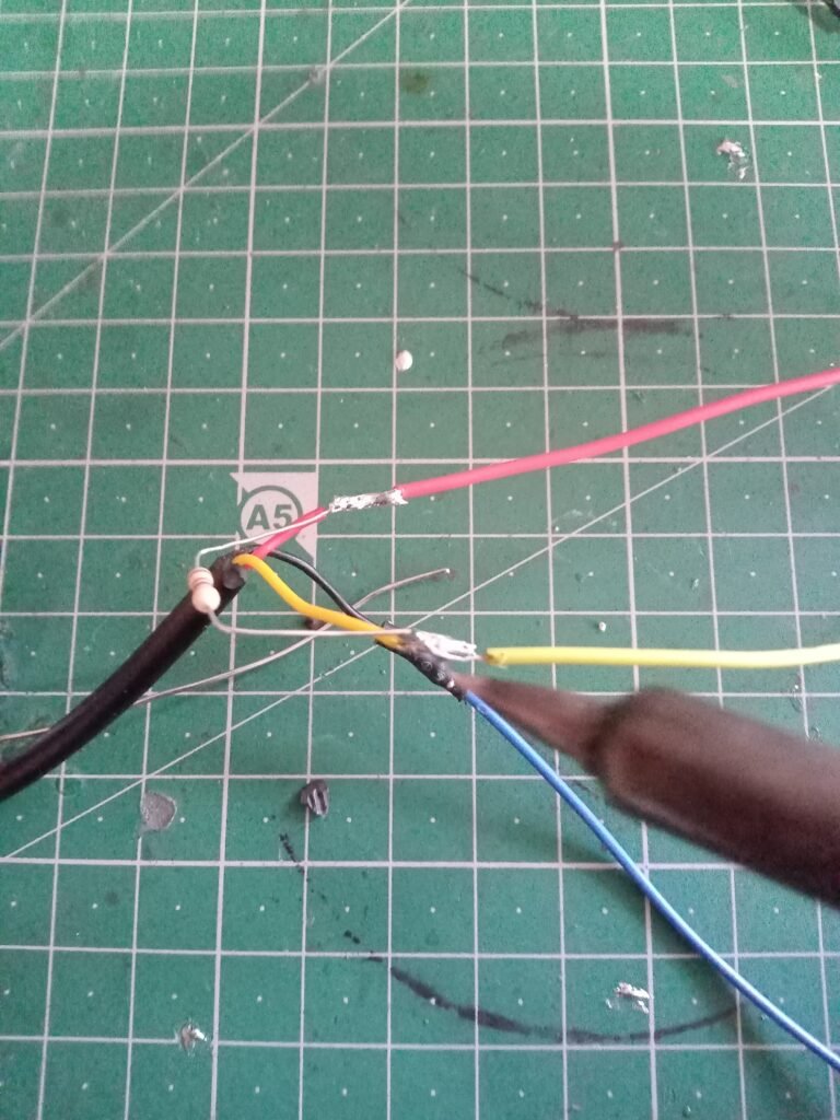
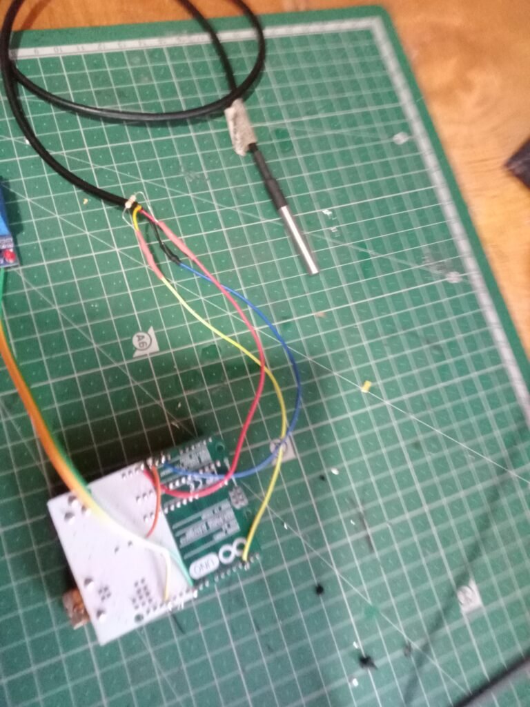
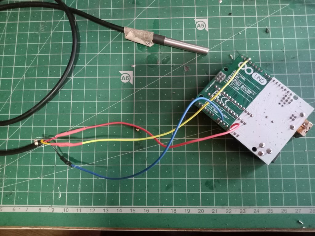
Start by connecting VCC to the 5V pin of the Arduino and GND to ground.
Connect the red wire of the DS18B20 to 5V, the black wire to ground, and the yellow wire to digital pin 2 on the Arduino. Still we have to connect 4.7K pullup resistor between data and 5V.
4.7k Resistance
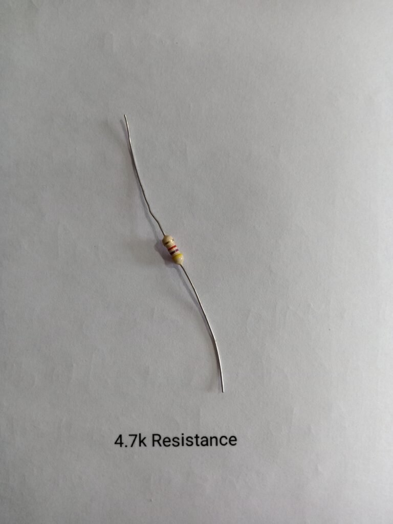
4.7K Ohm Resistor Color Code: Yellow, Violet, Red, Golden. Resistance: 4.7K Ohm, Power Rating: 0.25 Watt, Approximate Maximum Current: 7.29mA . Price: Rs 1.20 ~ 0.55.
relay (5v)
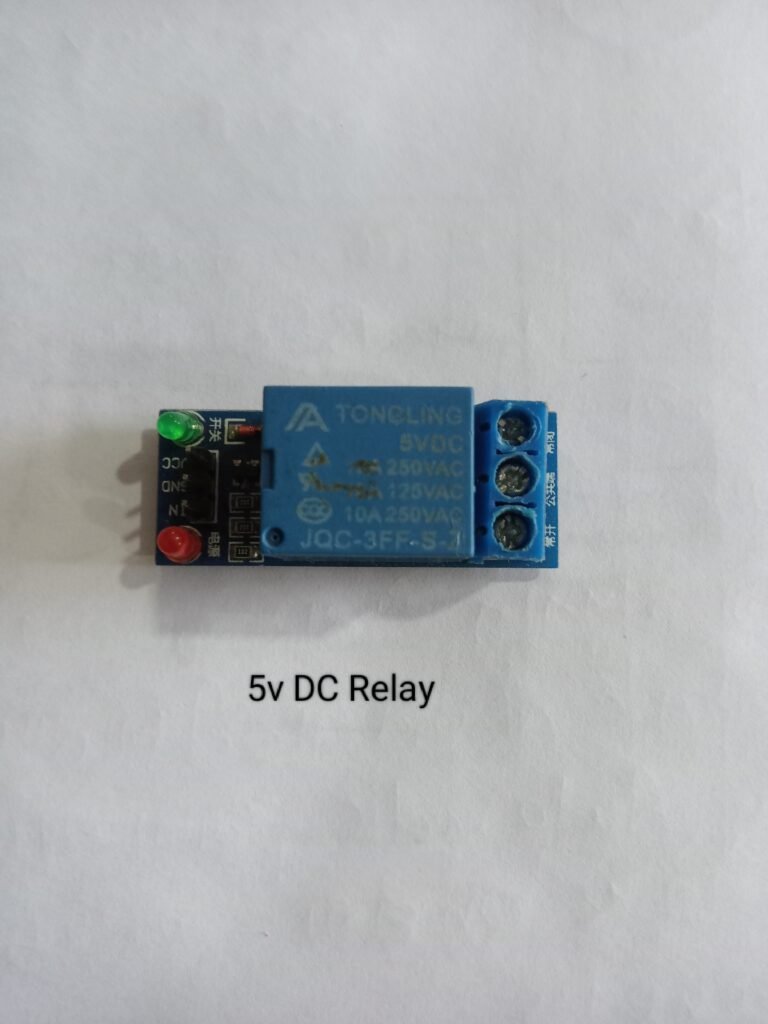
Relays are switches that open and close circuits electromechanically or electronically. Relays control one electrical circuit by opening and closing contacts in another circuit.
Normally Open Contact (NO) – No contact is also called make contact. It closes the circuit when the relay is activated. It disconnects the circuit when the relay is de-energized.
Normally Closed Contact (NC) – NC contact is also known as break contact. This is the opposite of NO contact. When the relay is activated, the circuit is disconnected. When the relay is de-energized, the circuit is connected.
Exit fan
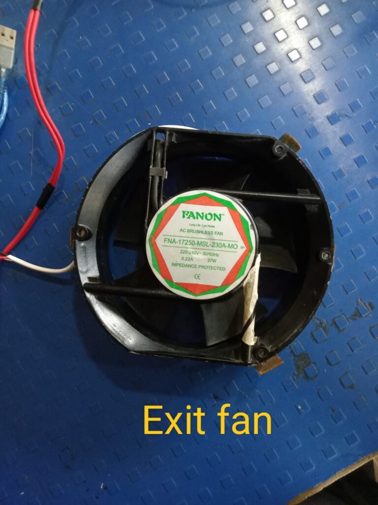
Ideal for extracting large amounts of air from industrial machinery rooms, workshops and other dusty areas. It also helps to remove excess water vapor from boiler rooms and cooling towers by exhausting them through roof ventilators.
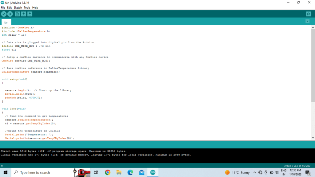

After soldering the components, coding was done in Arduino Uno. After that, I tested my set up by keeping at 30 degree centigrade. The code was prototyped to run the fan according to the measured temperature, then a temperature threshold was set to 50 degree to turn on the fan.

Circuit diagram :-
Code ;
#include <OneWire.h>
#include <DallasTemperature.h>
int relay = 10;
// Data wire is plugged into digital pin 2 on the Arduino
#define ONE_WIRE_BUS 2 //2 pin
float t1;
// Setup a oneWire instance to communicate with any OneWire device
OneWire oneWire(ONE_WIRE_BUS);
// Pass oneWire reference to DallasTemperature library
DallasTemperature sensors(&oneWire);
void setup(void)
{
sensors.begin(); // Start up the library
Serial.begin(9600);
pinMode(relay, OUTPUT);
}
void loop(void)
{
// Send the command to get temperatures
sensors.requestTemperatures();
t1 = sensors.getTempCByIndex(0);
//print the temperature in Celsius
Serial.print(“Temperature: “);
Serial.println(sensors.getTempCByIndex(0));
// Serial.print((char)176);//shows degrees character
Serial.print(” C | “);
if(t1>50)
{
digitalWrite(relay, LOW);
Serial.println(“Fan on”);
delay(500);
}
else
{
digitalWrite(relay, HIGH);
}
}
Assignment 5.Solar lamp with LDR +Relay

Introduction
Solar energy is clean and limitless, and operating costs are close to nothing once solar panels are installed because no fuel is needed to create a considerable amount of energy. It may help people living in remote areas with limited access to electricity.
Features :
- One day’s charging can light up for the night (about three times the brightness of a kerosene lamp).
- 2600mAh AA battery can be fully charged in the bright sunlight of the day. You can use the hanger as well as the multi-purpose stand for charging.
- Using a high quality battery which can work for at least 3 to 5 years.
- Uses a high quality solar panel to charge the battery.
- Automatically turns off in bright light to save charge and turns on in the dark. For this I use LDR sensor.
- Using multiprotection of battery over-discharge protection
Profit:
- The solar light bulb improves literacy because people can read after dark more easily than with a candle or kerosene lamp.
- Saves Energy: Since the light bulb is charged through solar energy (free energy), it saves energy.
- Reduces air pollution: The use of solar light bulbs reduces the amount of local air pollution. With the reduction in the amount of kerosene used for lighting, there has also been a reduction in the amount of pollution produced.
Step 1: Components :
- Solar Panel ( 5V /5watt )
- LDR (light-dependent resistor)
- Rechargeable Battery & Holder
- IC 7805
- Relay 5v Dc
- Multiple Protection
- 0.5W Straw Hat White LED
- wire
Step 2: Controller Selection
7805 Voltage Regulator IC :-

7805 Voltage Regulator IC Pinout, Circuit, and Applications
Voltage sources in a circuit may have fluctuations which may result in not providing a fixed voltage output. A voltage regulator IC maintains the output voltage at a constant value. The 7805 voltage regulator, a member of the 78xx series of fixed linear voltage regulators used to maintain such voltages, is a popular voltage regulator integrated circuit (IC).
The xx in 78xx indicates the output voltage it provides. The 7805 IC provides a +5 V regulated power supply with provisions for adding a heat sink.
7805 voltage regulator ic specification
Minimum input voltage is 7V
Max input voltage is 35V
Current rating I c = 1A
Maximum output voltage V max = 5.2 V
Minimum output voltage V min = 4.8V
LM7805 voltage regulator pinout
Relay :-

1 Channel 5V Relay Board Module for Arduino PIC AVR DSP ARM. A wide range of microcontrollers such as Arduino, AVR, PIC, ARM, etc. can control it. Each requires 15mA – 20mA driver current and is equipped with a high current relay: DC 5V / 10A, AC 250V / 10AStandard interface Which can be compatible with microcontroller.
Specification :-
1 channel relay board
Operating voltage 5V
Max Current: 20mA
Relay Contact Current Capacity at DC5V: 10A
one normally closed contact and one normally open contact
triode drive, boost relay coil
high impedance controller pin
Pull-down circuit to avoid malfunction
power supply indicator lamp
control indicator lamp
Indicator for relay output status
Various appliances and other devices can be controlled with large current.
LDR Sensor : –

LDR stands for Light Dependent Resistor and its resistivity varies with incident electromagnetic radiations, so its resistivity is a function of incident electromagnetic radiation or light. Other names for LDR are photoresistor, photoconductor, photocell and photo conducting cell
LDR is made of high resistance semiconductor material like silicon or germanium. It is a light-sensitive device, so this resistor has different resistance value in day and night, as given below
Daylight: 5000Ω
Dark: 20000000Ω
features
It requires less power to operate
Instant reaction
easy to use
Lithium-Ion Battery :-

Description
This is HONGLI Brand INR18650 2600mAh Lithium-Ion Battery with high quality 3C rated cells. It comes with a rated voltage of 3.7V and a capacity of 2600mAh. It is a single cell, compact and powerful battery cell with a capacity of 2600 mAh. Very convenient to install in your project to meet the requirement of 3.7V with high capacity.
The battery terminals can be used in any compatible battery adapter/holder or they can be permanently attached to your application’s power source wiring.
features :
High Power Density – 3C Rated
High working voltage for single battery cells.
pollution free
Long cycle life: 1500 cycles
No memory effect. The stability of capacity, resistance, voltage, platform time is good. Good stability and low self-discharge.
light, small size
Shape: Cylindrical Battery
Battery Type: Lithium-Ion Battery
Multiple Protection :-

Multiple Charging Method: This module is designed to charge rechargeable batteries/batteries using constant-current/constant-voltage (CC/CV) charging method, the charging port can take power from Micro USB. The input has a MIRCO USB socket, which can be used to charge directly with a 5V mobile phone charger, and still retain the input voltage wiring solder joints, which is very convenient….Input voltage : 4.5~5.5V.
Multiple Protection: This module is used for a single Lithium Ion / Lipo / 18650 cell or multiple cells in parallel, this board has overcharge, over discharge and overcurrent protection; Battery over-discharge protection voltage is 2.5V, battery over-current protection current is 3A
Adjustable Charging Current: The charge current can be modeled externally with Rprog resistor R3……default output is 4.12V ~ 4.2V and 1AMP ….it can also be used with other modules / robotics projects or Can be combined Work efficiently with other modules like custom torch, light, solar cell, Bluetooth, tester, wireless circuit, adapter, buzzer, power bank, camera, temperature sensor, audio circuit / headphone amplifier…etc.
Drive load: connect the battery to B+ B-, the indicator red light is being charged and blue light is full, OUT+ and OUT- are connected to the load,
Solar Panel ( 5V /5watt ) :

Peak Power: 5W/Working Voltage: 5V
Output Current: 1A
Solar Conversion Rate: >19%
Output Interface: USB
Use: mobile phone, digital camera, GPS, iPhone, mobile , bluetooth headset and other digital products
It can charge the device under direct sunlight, solar cell with different light intensity, charging time and high efficiency, small in size and easy to carry.
8mm Straw hat 0.5W White LED :-

Intensely Bright
Long lasting (over 100000hours)
Low Power Consumption
Application:
Viewing Angle: 140 Degree
Emitting Colour: White
Lens Type: Water Clear
Reverse Voltage: 5.0 V
Lead Soldering Temp: 260°C for 5 seconds
DC Forward Voltage: Typical: 3.0V Max: 3.6 V
DC Forward Current: 150mA
8mm Straw hat 0.5W White Light LED
Step 3: How the Circuit Works :-

The Solar Lamp is an SPV system and consists of four components
1.Solar Panel : Convert solar energy into electrical energy
2.Controller : Charge the battery (Charger) and drive the load (Driver)
3.Battery : store electrical energy
4.LED : Provide desired light output
Step 4: Breadboard Testing :-


Step 5: Solder the Components
I selected my PCB, and then connected the 7805 ic to it. I, then, soldered multiprotection in it.


Now I put the model relay in it, and I connect the LDR and the LED.


After connecting all components, I checked with multimeter. Then, I tried running it from 12v power supply.


I charged the battery with the solar panel.

Step 6: 3D Design


Finally
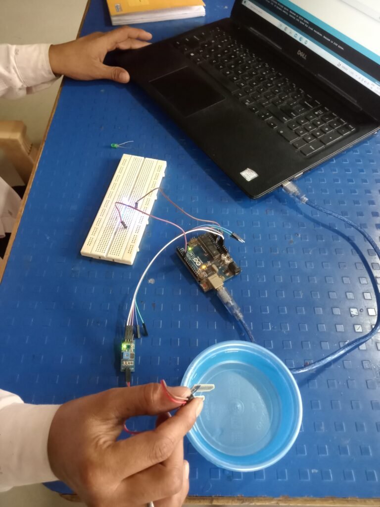
Soil Moisture Sensor with Arduino Uno
Components :-
Arduino Uno
soil moisture sensor
Led
bread board

About Soil Moisture Sensor
Most soil moisture sensors estimate the amount of water inside the soil based on the dielectric constant (soil bulk permittivity) of the soil dielectric. As the amount of water in the soil increases, the dielectric constant of the soil increases. This response is due to the fact that the dielectric constant of water is much greater than that of other soil components, including air.
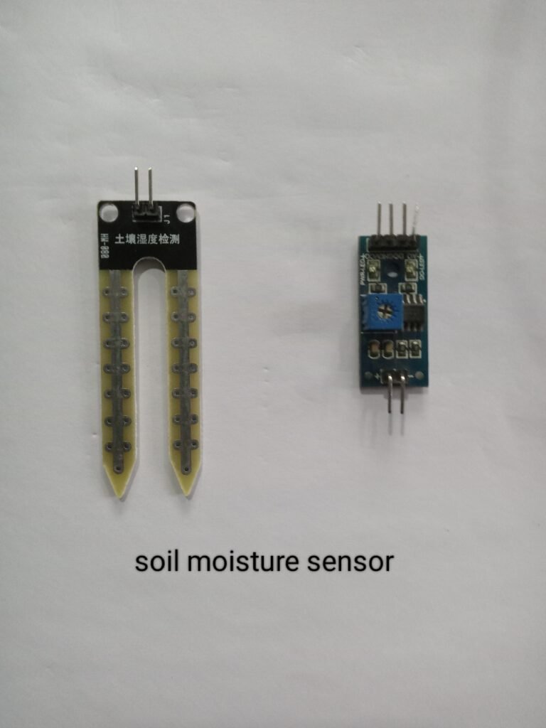
Connection
Connect the two pins from the sensor to the two pins on the amplifier circuit via hook up wires.
Connect the Vcc from the amplifier to the 3.3V pin on the Arduino and the Gnd pin to the Gnd pin on the Arduino.
Now connect the analog data pin to the (A0) pin on the Arduino
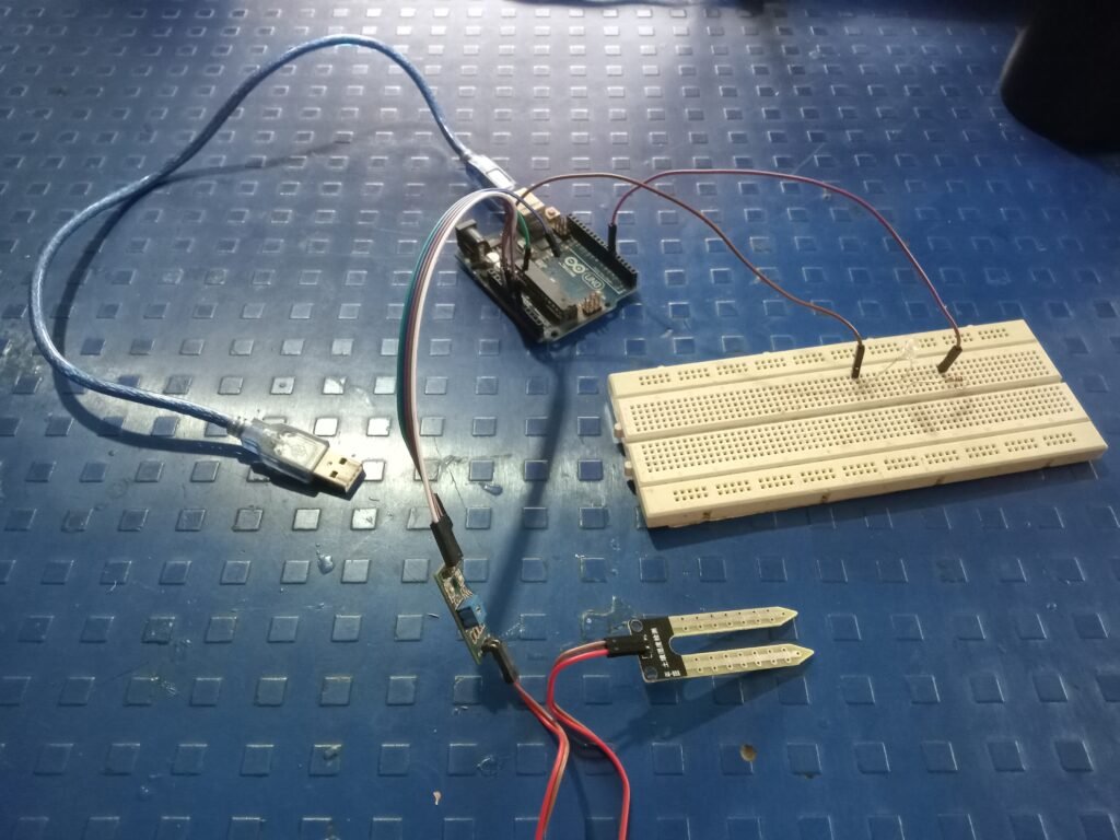

Code
void setup() {
  Serial.begin(9600);
}
void loop() {
    int sensorValue = analogRead(A0);
   Serial.println(sensorValue);
  delay(1);
}
After uploading the code, open the Serial Monitor. When the sensor leads are immersed in water and dried, you will see the sensor data change on the monitor.
Conclusion:-
By doing these assignment, I learned about Sensors, (LDR , Ultrasonic, Float,Soil Moisture Sensor, TemperatureDS18B20) and how to use Electronics. I also learned some programming skills, especially on Arduino uno and how to do SMPS connections.


