
Introduction
My name is Purneshwar Kumar Sahu. I’m learning product designing as a fellow at the Design Innovation Center of the Vigyan Ashram, Pabal. Currently, I’m working on an ‘LPG- based sanitary pad incinerator’ project.
Vigyan Ashram has already developed an LPG-based sanitary pad incinerator. Its loading capacity is 5 pads per operation. It is installed at the women’s hostel of the Vigyan Ashram.
Napate Institute is a Pune-based educational institute. They came to know about this incinerator in Dec 2021. They found it useful and placed an order for a similar LPG-based incinerator for their women’s hostel. Around 600-1000 female students live in their hostel and 100-150 pads are needed to be disposed every day there. Vigyan Ashram decided to deliver an LPG-based sanitary pad incinerator having 60 pads per operation loading capacity to Napate Institute, Pune.
17th Jan 2022
(Empathy)
| Location | Shri Bhagwanrao Napate Institute of Healthcare Education Institute, Paud, Pune 412108 |
| Installation | at the balcony of the Women’s hostel |
| Users | 600-1000 Women |
| Pads/day | 100-150 |
| Composition | In an average sanitary pad: 48% fluff pulp 36% PE, PP, and PET 7% adhesives 6% superabsorbent and 3% release paper |
24th Jan 2022
(Define)
”We are going to build an LPG-based sanitary pad incinerator having 60 pads/operation loading capacity.”
(We have already developed an LPG-based sanitary napkin incinerator having 5 napkins loading capacity. We are going to improve its design for better combustion of pads and pyrolysis gases. This improvement will also solve the blockage of the burner’s nozzle.)
7th Feb 2022
(Ideation)
Following are links to previous works of Vigyan Ashram in the field of incinerators development:
In the brainstorming sessions, we came up with the following ideas:
Process flow diagram

Material flow diagram
1) We are going to make a cage to load used sanitary napkins into it. This cage will be portable. Once the cage will be filled with around 30 napkins it will be placed inside the incinerator. This cage will have a central air vent.
2) We are going to install gas geyser burners inside the incinerator. We are going to place the burners in a vertical fashion, so the pyrolysis gases also get burned.
3) We are going to place the burners as shown in the below images. Such positioning of the burners will provide coverage of flame throughout the cage.

Design modelling
Sketches:


3D modeling
I was not familiar with the SolidWorks software for 3D modelling. So I started to learn to design a 3D model for the incinerator.
Part design:
- Sketch tools
- Feature tools


14th Feb 2022
(Ideation)
Assembly
Burners positions


21st Feb 2022
(Ideation)
Assembly
Pipe connection


28th Feb 2022
(Ideation)
Final assembly for prototype


28th Feb 2022
(Prototype)
Discussion: We decided to make a prototype to perform trials on it to achieve maximum combustion of used sanitary pads and pyrolysis gases.
We decided to use plastic pipes and plastic connectors while testing the prototype to reduce its cost of the prototype. To perform the trials safely, we are going to coat all the pipe connections with plaster of Paris. This will prevent plastic components to catch fire.
Bill of material: Please click the below link to view the BOM


7th March 2022
(Prototyping and Testing)
We needed flanges to connect burners with gas pipes. But, such flanges were not available in the market. Getting customized flanges from the market was too costly as we need only 6-8 flanges at the moment. So we decided to make such flanges at our workshop. We make it from MS washer and brass connectors. We cut the threaded head of brass connectors and glued it with MS washer with the help of Epoxy adhesive (Araldite). To avoid the leakage of gas, we put rubber washers between the flange and the burner’s inlet.


Testing
As we were going to use LPG gas, we took the trial in an open space for safety concerns. Also, we kept fire extinguishers, dirt, and water with us to prevent any accidents. We loaded 32 used napkins into the cage.


Results:
- All napkins burnt properly except the bottom-most layer.
- Pyrolysis gases burnt properly and the combustion was smokeless.
- Flame penetration was adequate to reach all areas inside the cage.
- It took 9 minutes to burn all the napkins completely.


Conclusion:
- Burner’s position worked well as per the ideation. It provided adequate flame penetration to all areas inside the cage.
- We need to place the burners a little lower so that flames can reach to bottom layer too.
28th March 2022
(Prototype)
We took 2nd trial with the following improvements:
- Earlier we tied the burners with the weldmesh cage. Burners were adjacent to the wall of the weldmesh cage. In this position inner cone (less hot part of the flame) was coming into the contact with pads. So we mounted the burners 1 cm apart from the walls of the weldmesh cage to make the outer cone (the hottest part of the flame) in contact with pads.


2. After 1st trial there were some partially burnt pads at bottom of the weldmesh cage. This happened because the burners were tied 2.5 cm above the bottom of the cage and the flame was not reaching the bottom layer of pads. To solve this issue we put a grid 2.5 cm above the bottom of the weldmesh cage.


3. We took the first trial by controlling LPG supply and ignition manually. The first trial was more focused on the position of burners to get maximum combustion of pads and pyrolysis gases. We got good results from the 1st trial. In 2nd trial, we were focused to control LPG supply and ignition automatically. Mr. Vrusabh Zunjurkar (former DIC fellow) made an electronic setup for the same.
Below is the circuit diagram for the electronic setup:


(Testing)
We took 2nd trial. It was focused to get proof of concept for the electronic system to control the LPG supply.

The outcome of the trial:
- The gas supply was regulated by a solenoid valve. Durations are mentioned in below table:
Alpha prototype
3D model and drafted drawings


Other drafted drawings can be found in the below link:
https://drive.google.com/drive/folders/1Dzr0nq0u0_147LDaOvMrQeWLp80sMTbj?usp=sharing
Bill of material
BOM can be found in the below link:
BOM needs to be updated.
Fabrication
Frame to mount the burners:


Outer cabinet:


Weldmesh cages:


Flanges: We couldn’t find ready-made flanges from the market. Available flanges in the market do meet the required dimensions of the flanges. Casting could be a solution but the cost of casting is very high. So we decided to make flanges at Vigyan Ashram only.
We cut discs of 40mm diameter from 6mm flat MS bars in the plasma cutter. Then we made grooves on them with the help of a lathe machine. These grooves will hold the o ring in position. Then we bore a hole at the centre for gas flow and two holes for screwing the flange with the manifold of the burner.


There are two kinds of manifolds in the burners. One is straight and the other one is tilted.


The cross-sectional area of the tilted manifold is an ellipse. So the central circular projection of the flange is not fitting in. So we made two types of flanges. One has a 3mm central projection and another has only a 1mm central projection. 1mm projection will provide a guide to the rubber O-ring.

Connecting part of the flange: We contacted Deep gas services, Pune which provides pipeline connections for LPG. They suggested a brass connector that has a two-sided threaded coupling and a bush to grab the copper pipe tightly.
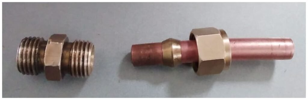
Further, they suggested making a pipe-like part in the flange of 8mm outer dia. So that the brass bush can be mounted on that pipe. We brought an MS pipe of 8mm outer dia. Then we tried to connect it with flanges with various welding methods.


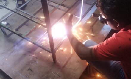
Among these methods, we got success to some extent with TIG welding. But due to the high temperature (around 3300 degrees celsius) of the arc, MS pipe was getting molten quickly and some holes were formed there.
While we were figuring out how to connect the MS pipe with flanges, we painted the cabinet and chimney of the incinerator. Before painting these we filled the cavities with metal putty.


We applied red oxide to the inner part and heat-resistant paint to the outer part of the incinerator. Heat resistance paint can withstand up to 600 degrees Celsius and it needs to be heat treated. For the heat treatment, we put the parts into the oven at the food lab of Vigyan Ashram. We put the parts for 1.5 hours at 200 degrees Celsius.


Flange: After discussions, we decided to make the flanges on the lathe machine with a single piece of the bar. To make the flanges we made a CAD design for the flanges and contacted A. K. Engineering Works, Bhosari for the lathe work.
Drafted drawing for the flanges:


Other drafted drawings can be found in the below link:
https://drive.google.com/drive/folders/1aaG8sseujT15g0vTSn4RBrWio-jmjc9G?usp=sharing
The flanges we got after lathe work didn’t work. The brass coupling system has a brash bush, which makes a tight grip on the copper pipe. MS is a harder material than copper. So the brass bush is not getting a proper grip on the MS.


Then we made internal threads on the flange to fit the brash coupling on it. To make it airtight we put o-rings between the coupling and flange.


Testing of flanges: We performed a leakage test on flanges at 2 bar pressure. All flanges passed the leakage test. Then we fitted those flanges into the burner system. Deep gas services, Pune is going to make a gas pipeline connection for the burner system.


