Introduction
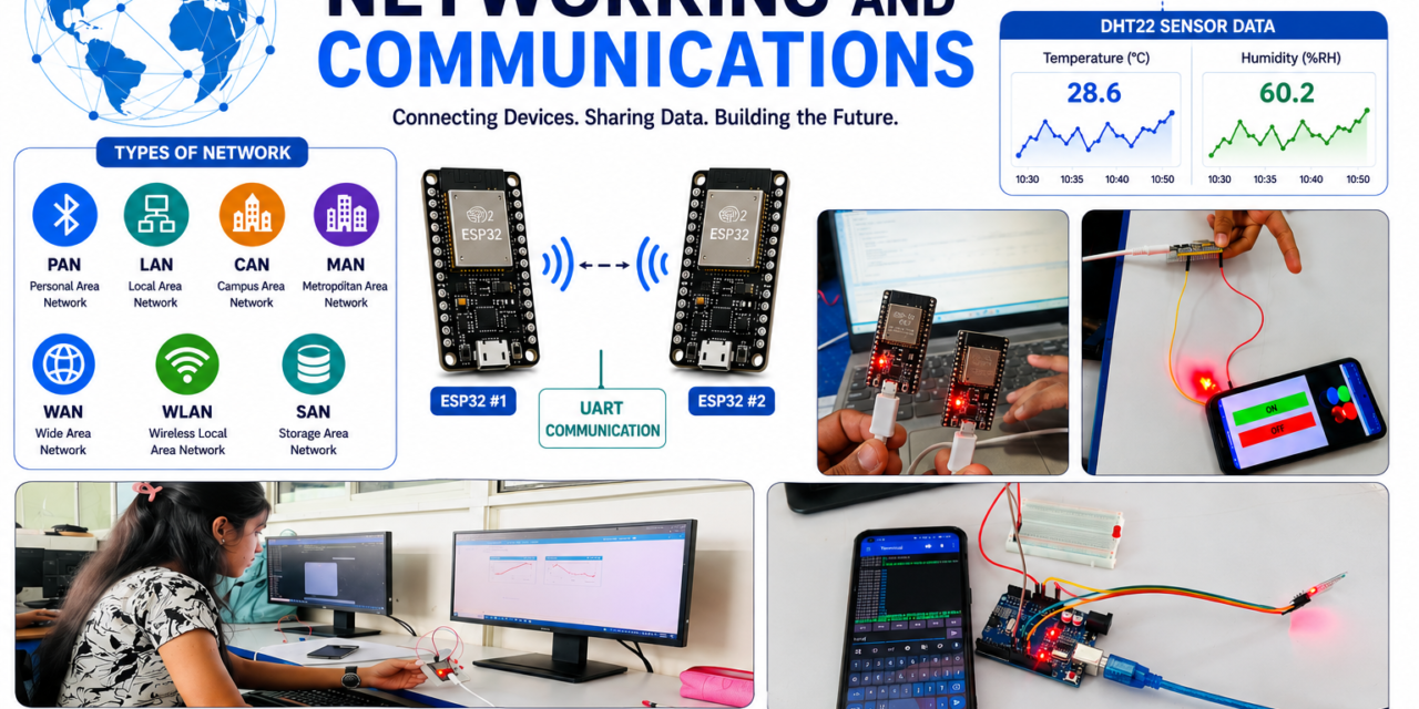
In Week 5, I learned about Networking and Communication. This week was very interesting because I learned how different devices and microcontrollers communicate with each other. Along with learning the theory, I also completed practical activities like communication between two MCU boards using UART, controlling an ESP32 LED using a mobile app created in MIT App Inventor, and sending DHT22 sensor data to ThingSpeak for cloud monitoring. These activities helped me understand the basics of communication protocols and IoT in a simple and practical way.
What is Network
A network is a group of two or more devices connected together to share information and communicate with each other.These devices can be computers, mobile phones, microcontrollers, sensors, printers, or other electronic devices.

Types of Network
Networks are classified based on how much area they cover and how many devices they connect.

| Type of Network | Description | Example |
|---|---|---|
| PAN(Personal Area Network) | A small network used around one person. | Mobile connected to Bluetooth earbuds |
| LAN(Local Area Network) | A network that covers a small area like a home, office, or school. | Computers connected in an office |
| CAN(Campus Area Network) | Connects multiple LANs within a campus or organization. | University campus network |
| MAN(Metropolitan Area Network) | Covers a city or large town area. | City-wide internet service |
| WAN(Wide Area Network) | Covers a large geographical area like countries or continents. | The Internet |
| WLAN(Wireless Local Area Network) | A LAN that uses wireless communication. | Wi-Fi network at home |
| SAN(Storage Area Network) | A high-speed network used for data storage. | Data centers |
Advertisement
Easy Examples:
- PAN: Phone + smartwatch using Bluetooth
- LAN: Devices connected to home Wi-Fi
- CAN: Network inside a college campus
- MAN: Network connecting offices across a city
- WAN: Internet connecting the whole world
What is Embedded Networking?
Embedded networking is the process of connecting embedded systems (such as microcontrollers, sensors, and IoT devices) so they can communicate and share data with each other.
Network vs Internet
| Network | Internet |
|---|---|
| A network is a group of devices connected to each other. | The Internet is a collection of many networks connected together. |
| It is used to share data between nearby devices. | It is used to connect people and devices all over the world. |
| It can work without the Internet. | It connects millions of networks globally. |
| Example: Two computers or two ESP32 boards connected together. | Example: Using Google, YouTube, WhatsApp, or ThingSpeak. |

Advertisement
Easy Example
- Network: Laptop and printer are connected to the same Wi-Fi and can share files.
- Internet: Phone to watch YouTube or upload DHT22 sensor data to ThingSpeak.
What is Communication?
Communication is the process of sending and receiving information between two or more devices.
In electronics and IoT, communication allows devices like microcontrollers, sensors, computers, and mobile phones to exchange data and work together.
Example
- Two ESP32 boards sending data using UART.
- A mobile app sending a command to an ESP32 to turn an LED ON or OFF.
Types of Communication
| Wired Communication | Wireless Communication |
|---|---|
| Uses wires or cables to send data.Wired communication means devices communicate using physical wires or cables. | Does not use wires; uses wireless signals.Wireless communication means devices communicate without wires using signals like Wi-Fi or Bluetooth. |
| Faster and more stable. | Easy to use and provides more flexibility. |
| Devices need to be physically connected. | Devices can communicate from a distance. |
| Less chance of signal interference. | Can be affected by signal problems. |
| Example: UART, I²C, SPI | Example: Wi-Fi, Bluetooth |
Advertisement
- Wired = Communication through wires
- Wireless = Communication without wires
Types of Wired Communication
1. UART (Universal Asynchronous Receiver-Transmitter)

- UART is a simple wired communication method.
- It uses mainly two wires: TX (Transmit) and RX (Receive).
- It is used for communication between two devices.
- Example: Communication between two MCU boards.
2. I²C (Inter-Integrated Circuit)

Advertisement
- I²C is a wired communication protocol that uses two wires:
- SDA (Serial Data line) →It carries the actual information or data.
- SCL (Serial Clock line)→It carries the actual information or data.
- It allows multiple devices to connect together.
- Example: Connecting sensors like temperature sensors with ESP32.
3. SPI (Serial Peripheral Interface)

- SPI is a fast wired communication protocol.
- It uses four main wires:
| Pin name | Function |
| MOSI (Master Out Slave In) | Sends data from the Master device to the Slave device. Example: ESP32 sends data to a display or sensor. |
| MISO (Master In Slave Out) | Sends data from Slave device to Master device Example:A sensor sends data back to ESP32 |
| SCK (Serial Clock) | Controls the timing of data transfer between Master and Slave(Provides timing/clock) |
| CS (Chip Select) | Selects the specific Slave device for communication.(Selects the sensor) |
Advertisement
Example: Connecting displays, memory chips, and sensors.

4. Ethernet
- Ethernet uses cables to connect devices in a network.
- It is used for high-speed data communication.
- Example: Computers connected to a router using LAN cables.
Synchronous vs Asynchronous Communication
Advertisement
| Synchronous Communication | Asynchronous Communication |
|---|---|
| Data is sent with a clock signal. | Data is sent without a clock signal. |
| Used for high-speed communication. | Used for simple communication. |
| Example: SPI, I²C | Example: UART |
- Synchronous = With Clock
- Asynchronous = Without Clock
Parallel vs Serial Communication
| Parallel Communication | Serial Communication |
|---|---|
| Sends multiple bits at the same time using multiple wires. | Sends one bit at a time using a single wire (or one pair of wires). |
| Faster over short distances. | Better for long distances. |
| Example: Older printer ports (Centronics), internal CPU-to-memory buses. | Example: USB, UART, SPI, I²C, Ethernet, SATA. |
Parallel Communication
Sender ReceiverBit 1 ───────────────►Bit 2 ───────────────►Bit 3 ───────────────►Bit 4 ───────────────►(All bits sent simultaneously)Serial Communication
Sender ───────────────► Receiver 1 → 0 → 1 → 1 → 0 → 1(One bit sent at a time)Types of Wireless Communication
Advertisement
Wireless communication allows devices to exchange data without wires using signals through the air.
| Wireless Communication Type | Simple Meaning | Example |
|---|---|---|
| Wi-Fi | Connects devices to the Internet without wires | Home Wi-Fi, ESP32 IoT |
| Bluetooth | Short-distance communication between devices | Mobile controlling ESP32, earbuds |
| NFC | Very short-distance communication | Contactless payment |
| RF (Radio Frequency) | Sends data using radio waves | Remote controls, wireless modules |
| 4G/5G | Mobile network communication | Mobile internet |
| Satellite | Communication using satellites | GPS, satellite internet |
| Infrared (IR) | Uses light signals(infrared light waves) for communication | TV remote |
What is IoT?
IoT connects everyday smart devices to the Internet so they can collect data, communicate, and be controlled automatically or remotely.
How IoT Works:
- Sensors collect data from the environment.
- Microcontroller (like ESP32) processes the data.
- Internet/Wireless communication sends the data.
- Cloud platform stores and displays the data.
Advertisement
Individual Assignment
In this week’s individual assignment, I learned about ThingSpeak, which is an IoT cloud platform used for collecting, storing, and visualizing sensor data. I created a ThingSpeak account and learned how to create channels to receive data from IoT devices. I also worked with the DHT22 temperature and humidity sensor and programmed the ESP32 to send sensor readings to ThingSpeak using Wi-Fi. The collected data was displayed in the form of graphs, which helped me understand real-time data monitoring and cloud-based IoT communication. This assignment improved my understanding of how IoT devices send data to the cloud and how users can monitor devices remotely.
A.Thingspeak
what is thingspeak
ThingSpeak is an online platform used for IoT projects. It helps devices like Arduino,ESP32 send data to the internet and store it in the cloud. Users can see this data on a mobile phone or computer in the form of graphs and charts. It is used for monitoring things like temperature, humidity, water level, and other sensor values from anywhere.
Creating account on thingspeak
1. Searched Thingspeak on google.

Advertisement
2. Opened Thingspeak website.

3. Signed-up Successfully.

Advertisement
4. Thingspeak interface

5. Created a new channel.Entered channel name “Temperature & Humidity Monitoring” then i added two fields, field 1 Temperature & field 2 with Humidity.

Advertisement
6. Saved channel

7. Channel interface

Advertisement
8. I connected the DHT22 sensor to the ESP32 wroom.

9. Installed the required libraries (DHT Library & Thingspeak Library) in the Arduino IDE.


Code
#include<WiFi.h>// Use <WiFi.h> for ESP32/XIAO ESP32C3#include<ThingSpeak.h>#include<DHT.h>#defineDHTPIN 2#defineDHTTYPE DHT22constchar* ssid = "YOUR_WIFI";constchar* password = "YOUR_PASSWORD";unsignedlongchannelID = YOUR_CHANNEL_ID;constchar* writeAPIKey = "YOUR_WRITE_API_KEY";WiFiClientclient;DHTdht(DHTPIN,DHTTYPE);voidsetup(){Serial.begin(115200);dht.begin();WiFi.begin(ssid,password);while(WiFi.status()!=WL_CONNECTED){delay(500);Serial.print(".");}Serial.println("\nWiFi Connected");ThingSpeak.begin(client);}voidloop(){floattemp = dht.readTemperature();floathum = dht.readHumidity();if(isnan(temp)||isnan(hum)){Serial.println("DHT Error");delay(2000);return;}ThingSpeak.setField(1,temp);ThingSpeak.setField(2,hum);intx = ThingSpeak.writeFields(channelID,writeAPIKey);if(x==200)Serial.println("Upload Successful");else{Serial.print("Error: ");Serial.println(x);}delay(20000); // ThingSpeak minimum update interval is 15 s}10. Uploaded the program to connect the board to Wi-Fi, read the DHT22 sensor values, and send the data to ThingSpeak. I entered my Wi-Fi credentials and the ThingSpeak Write API Key into the program.Uploaded the program to theESP32
Advertisement

11. I verified that the sensor data were successfully sent to ThingSpeak.

Advertisement
12. I viewed the temperature and humidity graphs on the ThingSpeak dashboard, where the data were updated automatically.

B.Blinking an LED with MIT App Inventor
As part of my individual assignment, I developed a mobile application using MIT App Inventor to control an LED over Wi-Fi. I designed a user interface with ON and OFF buttons and connected the application to the ESP32 wroom. When I pressed the buttons, the application sent commands over the Wi-Fi network, and the LED turned on or off accordingly. I tested the application successfully and confirmed that the LED responded correctly to the command.
Advertisement

1. I opened MIT App Inventor and designed the mobile application interface by adding ON and OFF buttons.

Advertisement
2. I wrote the program for the ESP32-WROOM in the Arduino IDE to control the LED through Wi-Fi. I entered my Wi-Fi credentials (Wi-Fi name and password) in the program so that the ESP32-WROOM could connect to the Wi-Fi network. I uploaded the program to the ESP32-WROOM using the Arduino IDE. After the ESP32-WROOM connected to the Wi-Fi network, I opened the Serial Monitor and copied the IP address assigned to the ESP32.

3. I returned to MIT App Inventor and completed the Blocks coding by entering the ESP32 wroom IP address so that the application could communicate with the ESP32.

4. I returned to MIT App Inventor and completed the Blocks coding by entering the ESP32 IP address so that the application could communicate with the ESP32.Saved the project and generated a QR code in MIT App Inventor. I scanned the QR code using my mobile phone and installed the application.


5. I opened the application on my mobile phone and ensured that the phone was connected to the same Wi-Fi network as the ESP32-WROOM. Finally, I pressed the ON and OFF buttons in the application to turn the LED on and off, verifying that the communication between the mobile application and the ESP32-WROOM was successful.


C. Individual Assignment: LED Control Using Arduino Uno and HC-06 Bluetooth Module
Advertisement
About HC-06 Bluetooth Module
The HC-06 Bluetooth module is a small electronic device used to provide wireless communication between a microcontroller and another Bluetooth-enabled device, such as a smartphone or computer. It communicates with the microcontroller through UART serial communication. The HC-06 generally works as a Bluetooth slave device, meaning it waits for a master device such as a phone to connect to it. It is commonly used in Arduino projects for applications such as robot control, home automation, sensor monitoring, and wireless data transfer.

| Name | Function |
|---|---|
| VCC | Power supply |
| GND | Ground |
| TXD | Transmits serial data to the microcontroller |
| RXD | Receives serial data from the microcontroller |
| STATE | Shows Bluetooth connection status (on some boards) |
| EN/KEY | Used for configuration/AT mode (on some boards) |
Advertisement
LED Control Using Arduino and HC-06 Bluetooth Module
For my individual assignment, I controlled an LED using an Arduino Uno and an HC-06 Bluetooth module. First, I placed an LED on a breadboard and connected it to the Arduino Uno.
Then, I connected the HC-06 Bluetooth module to the Arduino Uno using the required VCC, GND, TX, and RX connections.
| HC-06 Pin | Arduino Uno | Purpose |
|---|---|---|
| VCC | 5V | Power |
| GND | GND | Ground |
| TXD | D10 (RX) | HC-06 → Arduino |
| RXD | D11 (TX) | Arduino → HC-06 |
I uploaded the required program to the Arduino Uno, in which 1 was used as the command to turn the LED ON and 0 was used to turn the LED OFF. After powering the Arduino, I turned on Bluetooth on my mobile phone and searched for the HC-06 device.
Code
#include<SoftwareSerial.h>SoftwareSerialHC06(10,11); // Arduino RX, TXintLED = 8;voidsetup(){pinMode(LED,OUTPUT);HC06.begin(9600);}voidloop(){if(HC06.available()){chardata = HC06.read();if(data=='1'){digitalWrite(LED,HIGH);}if(data=='0'){digitalWrite(LED,LOW);}}}I selected the HC-06 and entered the pairing password 1234, after which the device was successfully paired with my mobile phone.
I then downloaded the Serial Bluetooth Monitor application and connected it to the paired HC-06 device. I entered 1 in the application and sent the command, which turned the LED ON. Similarly, I entered 0 and sent the command, which turned the LED OFF.


Finally, I tested both commands and successfully controlled the LED wirelessly from my mobile phone. Through this assignment, I learned about Bluetooth communication and wireless control of an LED using Arduino Uno and the HC-06 module.
Advertisement
Group Assignment
A. Communication Between Two esp32 Microcontroller Boards (Wireless Communication)
As part of our group assignment, we implemented wireless communication between two ESP32 boards using Wi-Fi. We programmed both ESP32 boards using the Arduino IDE and connected both boards to the same Wi-Fi network. We obtained the IP address of ESP32 board and used the IP address to establish communication between the two boards. One ESP32 was configured as the sender, while the other was configured as the receiver. When we sent a message from the sender ESP32, the message was transmitted through the Wi-Fi network using the receiver’s IP address, and the second ESP32 successfully received and displayed the message. We tested the system by sending different messages and verified that the communication worked correctly. Through this assignment, we gained practical knowledge of Wi-Fi-based wireless communication and IP address-based data transfer between two ESP32 boards.
Coding


ESP32 – Receiver Code
First we uploaded this code to the ESP32 that will receive the message.
#include<WiFi.h>constchar* ssid = "OPPOA5s";constchar* password = "megzzzzz";WiFiServerserver(5000);voidsetup(){Serial.begin(115200);WiFi.begin(ssid,password);Serial.print("Connecting to WiFi");while(WiFi.status()!=WL_CONNECTED){delay(500);Serial.print(".");}Serial.println();Serial.println("WiFi Connected");Serial.print("Receiver IP Address: ");Serial.println(WiFi.localIP());server.begin();Serial.println("Receiver is ready");}voidloop(){WiFiClientclient = server.available();if(client){Serial.println("Sender connected");while(client.connected()){if(client.available()){Stringmessage = client.readStringUntil('\n');Serial.print("Received: ");Serial.println(message);}}client.stop();Serial.println("Sender disconnected");}}After uploading, opened the Serial Monitor at 115200 baud.
Advertisement
Receiver IP Address: 192.168.43 (Copied this IP address.)
ESP32 – Sender Code
Then uploaded this code to the second ESP32.
#include<WiFi.h>constchar* ssid = "OPPOA5s";constchar* password = "megzzzzz";constchar* receiverIP = " 192.168.43";constintport = 5000;WiFiClientclient;voidsetup(){Serial.begin(115200);WiFi.begin(ssid,password);Serial.print("Connecting to WiFi");while(WiFi.status()!=WL_CONNECTED){delay(500);Serial.print(".");}Serial.println();Serial.println("WiFi Connected");Serial.print("Sender IP Address: ");Serial.println(WiFi.localIP());}voidloop(){if(Serial.available()){Stringmessage = Serial.readStringUntil('\n');if(client.connect(receiverIP,port)){client.println(message);Serial.print("Sent: ");Serial.println(message);client.stop();}else{Serial.println("Connection failed");}}}Changed in code:
const char* ssid = "OPPOA5s";const char* password = "megzzzzz";Serial.print("192,168,43");


Wired Communication Between Two XIAO ESP32-C3 Boards Using UART
In the second group assignment, we established wired communication between two Seeed Studio XIAO ESP32-C3 boards using the UART (Universal Asynchronous Receiver-Transmitter) protocol. Unlike Wi-Fi communication, UART transfers data directly through physical wires, making it one of the simplest and most reliable communication methods for embedded systems.
In this setup, one XIAO ESP32-C3 board acted as the Transmitter, while the other worked as the Receiver. The TX (Transmit) pin of one board was connected to the RX (Receive) pin of the second board, and similarly the RX pin was connected to the TX pin. The GND pins of both boards were also connected together to provide a common reference.
Whenever a message was entered in the Serial Monitor of one board, it was transmitted through the UART interface and displayed on the Serial Monitor of the other board. Likewise, replies could also be sent in the opposite direction, allowing two-way communication between both microcontrollers.
Hardware Connections
| Board 1 | Board 2 |
|---|---|
| TX | RX |
| RX | TX |
| GND | GND |
Board 1 (Transmitter & Receiver)
#include <HardwareSerial.h>HardwareSerial mySerial(1);void setup() { Serial.begin(115200); mySerial.begin(9600, SERIAL_8N1, 20, 21); Serial.println("Type a message and press Enter");}void loop() { if (Serial.available()) { String msg = Serial.readStringUntil('\n'); msg.trim(); mySerial.println(msg); Serial.print("You : "); Serial.println(msg); } if (mySerial.available()) { String reply = mySerial.readStringUntil('\n'); reply.trim(); Serial.print("Board 2 : "); Serial.println(reply); }}Board 2 (Transmitter & Receiver)
#include <HardwareSerial.h>HardwareSerial mySerial(1);void setup() { Serial.begin(115200); mySerial.begin(9600, SERIAL_8N1, 20, 21); Serial.println("Ready");}void loop() { if (mySerial.available()) { String msg = mySerial.readStringUntil('\n'); msg.trim(); Serial.print("Board 1 : "); Serial.println(msg); } if (Serial.available()) { String reply = Serial.readStringUntil('\n'); reply.trim(); mySerial.println(reply); Serial.print("You : "); Serial.println(reply); }}Working Process
- Connected the TX pin of Board 1 to the RX pin of Board 2.
- Connected the RX pin of Board 1 to the TX pin of Board 2.
- Connected the GND pins of both boards.
- Uploaded the transmitter program to Board 1.
- Uploaded the receiver program to Board 2.
- Opened the Serial Monitor for both boards.
- Typed a message on one board and observed it appearing on the other board.
- Repeated the process in the opposite direction to verify two-way communication.
Learning Outcome
This experiment provided a practical understanding of UART serial communication between two microcontrollers. I learned the importance of correctly connecting TX and RX pins, configuring the same baud rate on both devices, and using the Serial Monitor for testing communication. It also helped me understand how UART is widely used for connecting GPS modules, Bluetooth modules, GSM modules, and communication between different embedded systems. The activity improved my debugging skills and gave me confidence in implementing wired communication in future embedded and IoT projects.