
Introduction
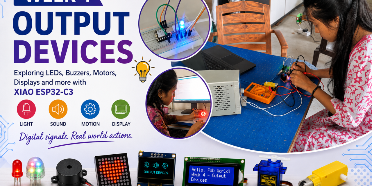
This week, I learned about Output Devices in the Fab Opportunity Academy. The main goal of this assignment was to understand what output devices are, learn about different types of output components, and see how they work in electronic circuits. During this week, I learned about devices such as LEDs, buzzers, motors, and displays, their functions, and how they are connected to a microcontroller. I also understood how digital signals control output devices and how these devices respond to programmed instructions to produce light, sound, motion, or visual information.
What are Output Devices
Output devices are electronic components that receive signals from a microcontroller or computer and convert them into a physical action or response, such as light, sound, movement, or visual information. They allow an electronic system to communicate with users or interact with its environment.

Output Devices I Learned
This week, I explored various types of output devices used in electronics and Arduino projects. I learned how output devices receive signals from a microcontroller and convert them into physical outputs such as light, sound, movement, and visual displays. I explored how different output devices are connected to a microcontroller and how they respond to programmed instructions to perform specific actions. The output devices I studied include the LED, buzzer, dot matrix display, OLED display, LCD display, SG90 servo motor, yellow BO motor, relay, stepper motor, and fan. I also learned how digital and PWM signals are used to control different output devices and how each device operates based on the signals received from the microcontroller. This helped me understand how output devices are used in real-world applications such as home automation, robotics, industrial automation, security systems, and smart electronic devices.

Output Devices Datasheet
Output Devices Programming With XIAO ESP32-C3 Board (Individual assignment)
1. LED
A Light Emitting Diode (LED) is a semiconductor electronic component that emits light when an electric current passes through it. It is one of the most common output devices used in electronic circuits to provide visual indications such as power status, notifications, and signals.
When the anode is at a higher voltage than the cathode, current flows through the LED, causing it to emit light. A current-limiting resistor is typically connected in series with the LED to prevent excessive current that could damage it.
| Parameter | Value |
|---|---|
| Operating Voltage | 1.8–3.3 V |
| Forward Current | 10–20 mA |
| Power Consumption | Low |
| Polarity | Anode (+), Cathode (−) |
| Output | Visible light |

LED Programming
To blink one LED ON and OFF using an Xiao ESP32-C3 board, I connected the LED anode to GPIO 2 pin of the Xiao ESP32-C3 board and controlled it using a simple program.


Code
#defineLED_PIN 2voidsetup(){pinMode(LED_PIN,OUTPUT);}voidloop(){digitalWrite(LED_PIN,HIGH); // LED ONdelay(1000); // wait 1 seconddigitalWrite(LED_PIN,LOW); // LED OFFdelay(1000); // wait 1 second}Outcome
The GPIO 2 pin was set as an output pin to turn the LED ON and OFF at regular intervals, making the LED blink.
RGB LED
An RGB LED is a type of LED that can produce different colors by combining three light sources: Red, Green, and Blue. By changing the brightness of each color using a controller or PWM signals, it can create millions of colors, including white. RGB LEDs are commonly used in LED strips, displays, smart lighting, and electronic projects because they are small, energy-efficient, and easy to control.

RGB LED Programming
In this experiment, I am controlling an RGB LED using an Xiao ESP32-C3 board.
First, I connected the common GND pin of the RGB LED to the GND pin of the Xiao ESP32-C3
Then I connected the RGB LED pins to the GPIO pins of the ESP32-C3 Xiao:
- Red pin to GPIO 2
- Green pin to GPIO 3
- Blue pin to GPIO 4
After making the connections, I uploaded my code to the Xiao ESP32-C3 board.


Code
#defineRED_PIN 2#defineGREEN_PIN 3#defineBLUE_PIN 4Stringcolor = "cycle";voidsetup(){Serial.begin(115200);pinMode(RED_PIN,OUTPUT);pinMode(GREEN_PIN,OUTPUT);pinMode(BLUE_PIN,OUTPUT);offLED();Serial.println("Type: red, green, blue");}voidloop(){// Check Serial inputif(Serial.available()){color = Serial.readStringUntil('\n');color.trim();color.toLowerCase();Serial.print("Selected: ");Serial.println(color);}if(color=="red"){blinkColor(HIGH,LOW,LOW);}elseif(color=="green"){blinkColor(LOW,HIGH,LOW);}elseif(color=="blue"){blinkColor(LOW,LOW,HIGH);}else{// Default RGB cycledigitalWrite(RED_PIN,HIGH);digitalWrite(GREEN_PIN,LOW);digitalWrite(BLUE_PIN,LOW);delay(500);digitalWrite(RED_PIN,LOW);digitalWrite(GREEN_PIN,HIGH);digitalWrite(BLUE_PIN,LOW);delay(500);digitalWrite(RED_PIN,LOW);digitalWrite(GREEN_PIN,LOW);digitalWrite(BLUE_PIN,HIGH);delay(500);}}voidblinkColor(intr,intg,intb){digitalWrite(RED_PIN,r);digitalWrite(GREEN_PIN,g);digitalWrite(BLUE_PIN,b);delay(500);offLED();delay(500);}voidoffLED(){digitalWrite(RED_PIN,LOW);digitalWrite(GREEN_PIN,LOW);digitalWrite(BLUE_PIN,LOW);}Outcome
I programmed the Xiao ESP32-C3 using the Arduino IDE to receive color commands from the Serial Monitor.In this code, when I type a color name like red, green, or blue in the Serial Monitor, the RGB LED starts blinking with that particular color.
2. Buzzer
A buzzer is an electronic output device that produces sound when it receives an electrical signal from a microcontroller or power source. It converts electrical energy into sound and is commonly used to give alerts, warnings, or notifications. Buzzers are widely used in alarm systems, doorbells, timers, home appliances, and Arduino projects to provide audio feedback.

Buzzer Programming
I connected the buzzer to the XIAO ESP32-C3 board by connecting the GND pin of the buzzer to the GND pin of the board and the anode (+) pin of the buzzer to GPIO 2.


Code
#defineBUZZER_PIN 2voidsetup(){pinMode(BUZZER_PIN,OUTPUT);}voidloop(){digitalWrite(BUZZER_PIN,HIGH); // Turn buzzer ONdelay(1000); // Wait 1 seconddigitalWrite(BUZZER_PIN,LOW); // Turn buzzer OFFdelay(1000); // Wait 1 second}Outcome
I controlled the buzzer using the GPIO 2 pin to turn it ON and OFF through the ESP32-C3 program.
3. Dot Matrix display
An 8×8 Dot Matrix Display is an electronic output device made up of 64 LEDs arranged in 8 rows and 8 columns. It is used to display letters, numbers, symbols, and simple animations by turning individual LEDs on and off. The microcontroller controls the LEDs by sending signals to the rows and columns, creating different patterns on the display.It is widely used in digital clocks, scrolling message boards, scoreboards, information displays, and various embedded system projects.

Dot Matrix Display Programming
I connected the 8×8 dot matrix module to the XIAO ESP32-C3 board using the VCC and GND pins for power and connected the DIN, CS, and CLK pins to GPIO pins of the ESP32-C3 for communication.
Connections:
| Dot Matrix (MAX7219) Pin | XIAO ESP32-C3 Pin | Purpose |
|---|---|---|
| VCC | 5V | Power supply |
| GND | GND | Ground connection |
| DIN | GPIO 2 | Data input |
| CS | GPIO 3 | Chip select |
| CLK | GPIO 4 | Clock signal |


Code
#include<MD_MAX72xx.h>#include<SPI.h>#defineHARDWARE_TYPE MD_MAX72XX::FC16_HW#defineMAX_DEVICES 1#defineDATA_PIN 2#defineCLK_PIN 4#defineCS_PIN 3MD_MAX72XXmatrix = MD_MAX72XX(HARDWARE_TYPE,DATA_PIN,CLK_PIN,CS_PIN,MAX_DEVICES);bytesmile[8] = {B00111100,B01000010,B10100101,B10000001,B10100101,B10011001,B01000010,B00111100};bytesad[8] = {B00111100,B01000010,B10100101,B10000001,B10011001,B10100101,B01000010,B00111100};voiddisplayFace(byteface[]){matrix.clear();for(introw = 0; row<8; row++){matrix.setRow(0,row,face[row]);}}voidsetup(){Serial.begin(115200);matrix.begin();matrix.clear();Serial.println("Type 's' for Smile and 'd' for Sad");}voidloop(){if(Serial.available()){charinput = Serial.read();if(input=='s'){displayFace(smile);Serial.println("Smile displayed");}elseif(input=='d'){displayFace(sad);Serial.println("Sad displayed");}}}Outcome
I programmed the Xiao ESP32-C3 to receive commands from the Serial Monitor. When I typed ‘s’, the dot matrix displayed a smiley face, and when I typed ‘d’, it displayed a sad face, demonstrating that the ESP32-C3 can control the dot matrix display through serial communication.
4. OLED Display
An OLED (Organic Light-Emitting Diode) display is an electronic output device that is used to show text, numbers, images, and simple graphics. It produces its own light, so it does not need a backlight like an LCD. This makes the display bright, clear, and easy to read while using less power. OLED displays are easy to connect to microcontrollers such as Arduino and are commonly used in clocks, weather stations, IoT projects, and other embedded systems to display information.

5. LCD
An LCD (Liquid Crystal Display) is an electronic output device used to show text, numbers, and information on a screen. It works by using liquid crystals to control light and create characters or images. A common type used in Arduino projects is the 16×2 LCD, which can display 16 characters in 2 rows. LCD displays are easy to connect with microcontrollers and are commonly used in digital clocks, calculators, control panels, and electronic projects to show data.

LCD Programming
I connected the 16×2 I2C LCD display to the XIAO ESP32-C3 board by connecting the pins.
Connections:
| LCD (I2C) Pin | XIAO ESP32-C3 Pin | Purpose |
|---|---|---|
| VCC | 5V | Provides power to the LCD |
| GND | GND | Ground connection |
| SDA | GPIO 6 (SDA) | Transfers data between the LCD and ESP32-C3 |
| SCL | GPIO 7 (SCL) | Provides the clock signal for I2C communication |


Code
#include<Wire.h>#include<LiquidCrystal_I2C.h>#defineSDA_PIN 6#defineSCL_PIN 7LiquidCrystal_I2Clcd(0x27,16,2); // Change to 0x3F if neededvoidsetup(){Serial.begin(115200);Wire.begin(SDA_PIN,SCL_PIN);lcd.init();lcd.backlight();Serial.println("Type a message and press Enter:");}voidloop(){if(Serial.available()){Stringtext = Serial.readStringUntil('\n');text.trim();lcd.clear();lcd.setCursor(0,0);lcd.print(text);Serial.print("Displayed: ");Serial.println(text);}}Outcome
The LCD successfully displayed the name “AKSHARA” entered through the Serial Monitor, demonstrating that the XIAO ESP32-C3 can receive serial input and display it on an LCD in real time.
6. Servo Motor SG90
A SG90 servo motor is a small output device that is used to control movement at a specific angle. It can rotate from 0° to 180° and is controlled by signals from a microcontroller like Arduino. The servo motor contains a small motor, gears, and a control circuit that helps it move accurately to the required position. It is commonly used in robotics, robotic arms, automatic doors, and small electronic projects where precise movement is needed.

Servo Motor SG90 Programming
I connected the servo motor to the XIAO ESP32-C3 board and used the ESP32Servo library to control it. I wrote a simple program that moves the servo to 0°, 90°, and 180°, with a one-second delay between each position.I connected the three pins of the servo motor to the XIAO ESP32-C3 board as follows:
| Servo Motor Pin | Connected to XIAO ESP32-C3 | Purpose |
|---|---|---|
| VCC (Red wire) | 5V | Provides power to the servo |
| GND (Brown wire) | GND | Common ground connection |
| Signal (Orange wire) | GPIO 2 | Sends control signal to move the servo |


Code
#include<ESP32Servo.h>Servoservo;voidsetup(){servo.attach(D6);}voidloop(){servo.write(0);delay(1000);servo.write(90);delay(1000);servo.write(180);delay(1000);}Outcome
After uploading the code, I observed that the servo continuously rotated between these three angles, confirming that the motor and its connections were working correctly.the program repeatedly rotates the servo to 0°, 90°, and 180°, pausing for one second at each position.
7.Yellow BO Motor
A Yellow BO motor (Battery Operated motor) is a small DC geared motor that is used to make robots and other electronic projects move. It converts electrical energy into rotational movement. The motor has built-in gears that reduce the speed and increase the power (torque), making it suitable for driving robot wheels. It is easy to connect with Arduino using a motor driver and is commonly used in line-following robots, obstacle-avoiding robots, and other DIY robotics projects.

8. Relay
A relay is an electronic output device that works like an electrical switch. It uses a small electrical signal from a microcontroller, such as an Arduino, to turn high-voltage or high-current devices ON or OFF safely. When the relay receives a signal, it opens or closes the circuit to control devices like lights, fans, motors, and pumps. It is commonly used in home automation, industrial control, and electronic projects.
| Relay | Relay Module |
|---|---|
| A relay is an electrical switch that controls high-voltage or high-current devices ON and OFF. | A relay module is a circuit board that contains a relay and extra components for easy connection to a microcontroller. |
| It is a single component. | It is a complete board with a relay, transistor, diode, resistor, LED, and input pins. |
| It usually requires additional components to connect with an Arduino. | It can be connected directly to an Arduino using VCC, GND, and IN pins. |
| Used in electronic circuits. | Used in Arduino and automation projects. |

Relay Module Programming
I connected the relay module to the XIAO ESP32-C3 board by connecting the IN pin of the relay module to GPIO2, VCC to the power supply, and GND to the common ground. I put a program to switch the relay ON for one second and OFF for one second continuously.
Connections:
| Relay Module Pin | XIAO ESP32-C3 Pin | Purpose |
|---|---|---|
| VCC | 5V | Power supply |
| GND | GND | Common ground |
| IN | GPIO2 (D2) | Control signal from ESP32-C3 |


Code
constintrelayPin = 2; // GPIO2voidsetup(){pinMode(relayPin,OUTPUT);}voidloop(){digitalWrite(relayPin,HIGH); // Relay ONdelay(1000); // Wait 1 seconddigitalWrite(relayPin,LOW); // Relay OFFdelay(1000); // Wait 1 second}Outcome
After uploading the code, I observed that the relay clicked and its indicator LED turned on and off, confirming that the ESP32-C3 successfully controlled the relay module.
9. Stepper Motor
A stepper motor is an electronic output device that rotates in small, fixed steps instead of spinning continuously like a DC motor. It receives signals from a microcontroller, which controls the direction, speed, and number of steps it moves. This allows the motor to move very accurately to a specific position. Stepper motors are commonly used in 3D printers, CNC machines, robotic arms, cameras, and other projects that require precise movement.

10. Cooling Fan
A cooling fan is an electronic output device that is used to move air and remove heat from electronic devices and systems. It converts electrical energy into rotational movement, causing its blades to spin and create airflow. Cooling fans help keep components such as computers, power supplies, motors, and electronic circuits from overheating. They are commonly used in computers, home appliances, industrial equipment, and Arduino projects to improve cooling and ensure safe operation.

11. DC Motor
A DC motor with a fan blade is a device that converts electrical energy into mechanical energy to produce rotation. A fan blade is attached to the shaft of the DC motor, and when DC power is supplied, the motor rotates the blade to create airflow. The speed and direction of the motor can be controlled by changing the input voltage or using a motor driver. DC motors with fan blades are commonly used in cooling systems, small fans, electronic devices, and ventilation systems. They are simple, lightweight, and easy to operate.

Outcome

12. 7-Segment Display
A 7-segment display is an electronic display used to show numbers and some letters. It has seven LED segments arranged in the shape of the number 8. These segments are named a to g and can be turned ON or OFF to display different digits from 0 to 9. It is used in devices like digital clocks, calculators, and counters. There are two types of 7-segment displays: common cathode and common anode. It is simple, low-cost, and easy to use in electronic circuits.

Group Assignment
Measured the power consumption of an output device (Yellow BO Motor)
What Is Yellow BO Motor ?
A Yellow BO motor is a small DC geared motor commonly used in robotics and DIY electronics projects. It is called a BO motor because it is often used with BO (Battery Operated) robot chassis kits. The motor has a built-in gearbox that reduces speed and increases torque, allowing it to move wheels and carry small loads.
Connecting a Yellow BO Motor with Arduino Uno:


As a part of our group assignment, we worked on connecting a yellow BO motor with an Arduino Uno. First, we programmed the Arduino Uno to control the motor and then attached a wheel to the shaft of the yellow BO motor. To power the DC motor, we used a variable power supply so that we could adjust and provide the required voltage. After setting up the circuit and running the motor, we measured the voltage and current of the toy DC motor using a multimeter. During the measurement, we observed that the motor operated at approximately 8.83 volts and consumed a current of about 1.04 amperes. This experiment helped us understand the working of DC motors, motor interfacing with Arduino, and the importance of measuring electrical parameters in practical applications.
Curret & Voltage of Yellow BO Motor


Power Consumption by BO Motor :
P=V×I
Where:
- P = Power (Watts, W)
- V = Voltage (Volts, V)
- I = Current (Amperes, A)
- Power=Voltage×Current
- Power=8.83 volt× 1.04 ampere
- Power=9.18 watt


