Introduction
This week in Fab Lab, we learned about networking and communication in embedded systems. We studied how different devices and microcontrollers communicate with each other and exchange data. We also understood the importance of communication protocols and how they help devices share information quickly and accurately.
We learned about different types of communication used in embedded systems, including UART, SPI, and I2C. We also studied synchronous and asynchronous communication and understood the difference between them. In addition, we learned about IP addresses and how they help identify devices connected to a network.
As part of the practical work, we explored IoT platforms such as ThingSpeak. We learned how to send sensor data from a microcontroller to ThingSpeak and display the data on graphs.
We understood how to use programming blocks to connect the app with ThingSpeak and display sensor data.
Overall, this week helped us understand the basics of embedded networking and communication. We gained both theoretical knowledge and practical experience in connecting devices, transferring data, and building a simple IoT system using embedded hardware, ThingSpeak. This knowledge will help us develop more advanced IoT and embedded system projects in the future.
Group Assignment
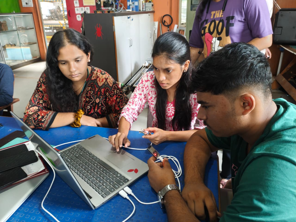
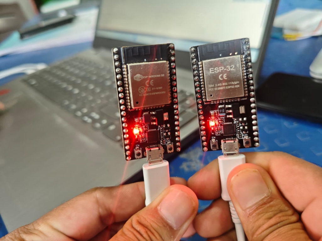
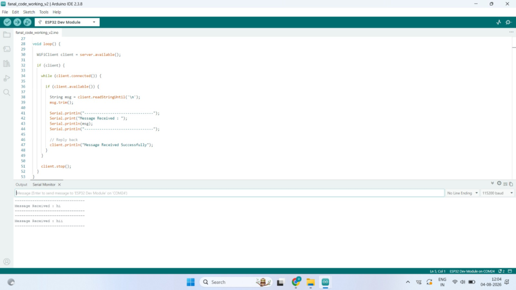
As a part of the group assignment, we established communication between two Seeed Studio XIAO ESP32-C3 microcontroller boards. The objective was to understand how two embedded devices can exchange data using a communication protocol. We programmed one XIAO ESP32-C3 board to send data, while the other board received the data successfully.
During this assignment, we learned how communication takes place between two microcontrollers, how data is transmitted and received, and the importance of proper wiring and programming. This activity helped us understand the practical implementation of embedded communication and improved our knowledge of networking concepts used in embedded systems.
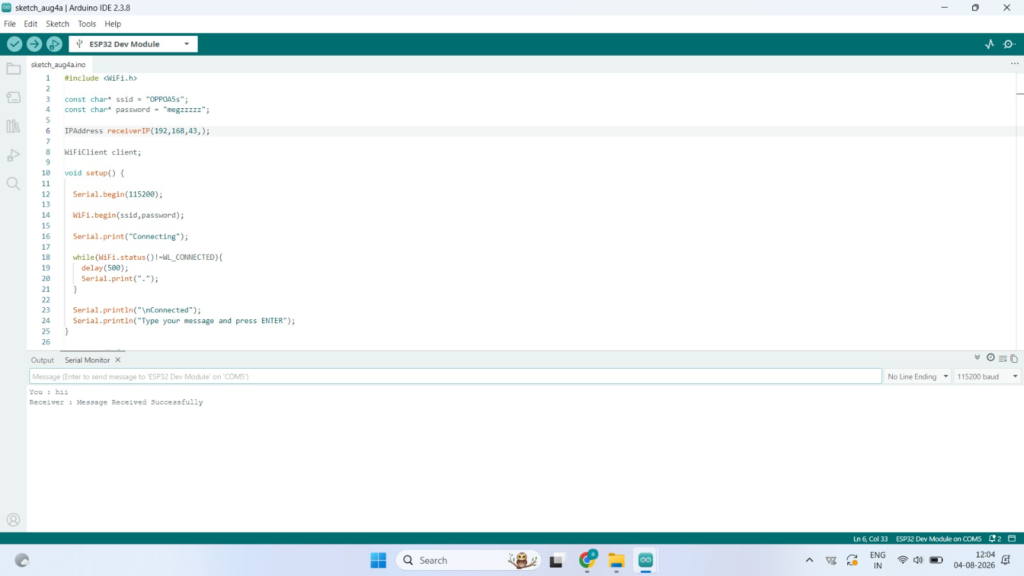
Code used
#include <WiFi.h>

const char* ssid = "YOUR_WIFI_NAME";
const char* password = "YOUR_WIFI_PASSWORD";

WiFiServer server(80);

const int ledPin = 2;   // Built-in LED

void setup() {
  Serial.begin(115200);

  pinMode(ledPin, OUTPUT);
  digitalWrite(ledPin, LOW);

  WiFi.begin(ssid, password);

  Serial.print("Connecting");

  while (WiFi.status() != WL_CONNECTED) {
    delay(500);
    Serial.print(".");
  }

  Serial.println();
  Serial.print("ESP32 IP Address: ");
  Serial.println(WiFi.localIP());

  server.begin();
}

void loop() {

  WiFiClient client = server.available();

  if (!client) return;

  String request = client.readStringUntil('\r');
  client.flush();

  if (request.indexOf("/ON") != -1) {
    digitalWrite(ledPin, HIGH);
  }

  if (request.indexOf("/OFF") != -1) {
    digitalWrite(ledPin, LOW);
  }

  client.println("HTTP/1.1 200 OK");
  client.println("Content-type:text/html");
  client.println();
  client.println("OK");
  client.stop();
}
Individual Assignment
Design and connect wired and wireless network nodes with local input and output devices.
Developing a DHT11 Temperature and Humidity Monitoring System Using ThingSpeak.
I connected a DHT11 temperature and humidity sensor with the XIAO ESP32-C3 microcontroller to monitor environmental conditions. The sensor continuously measured the temperature and humidity, and the microcontroller processed the collected data. After uploading the program, the sensor readings were first displayed on the Arduino IDE Serial Monitor, allowing me to verify that the sensor was working correctly and providing accurate values.
Next, I connected the microcontroller to the internet and sent the sensor data to the ThingSpeak cloud platform. ThingSpeak stored the received data and displayed it in the form of graphs, making it easy to monitor the temperature and humidity over time. Finally, I developed a simple mobile application using MIT App Inventor that retrieved the latest data from ThingSpeak and displayed it on my phone. This project successfully demonstrated wireless data transmission from the sensor to the microcontroller, then to the cloud, and finally to a mobile application, showing a complete IoT-based monitoring system
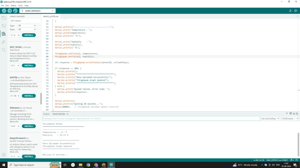
This was when we connected it and the signals were on serial monitor
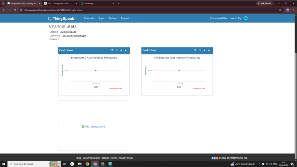
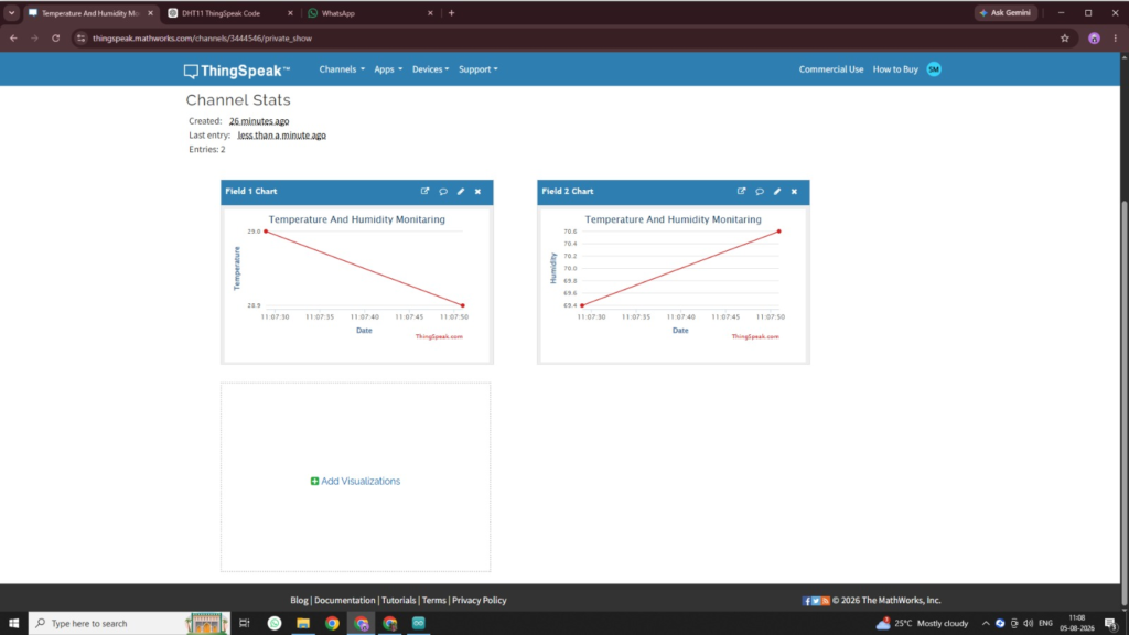
slowly the graph started changing
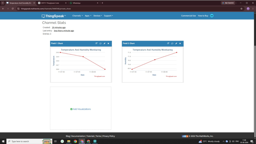
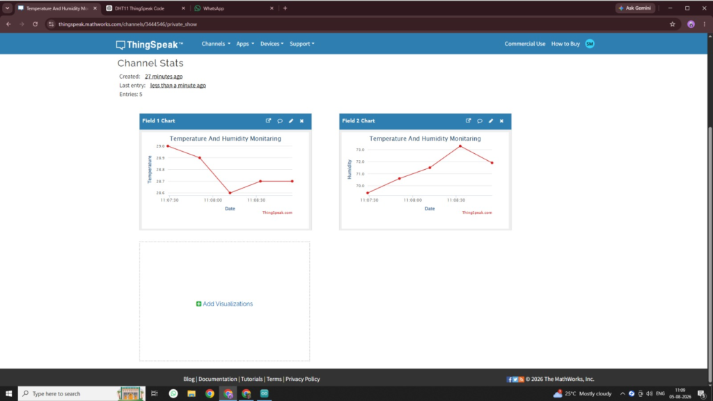
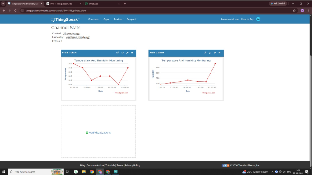
And accordingly it changed
Code Used
#include <WiFi.h>
#include <ThingSpeak.h>
#include <DHT.h>

#define DHTPIN 2
#define DHTTYPE DHT11

const char* ssid = "Redmi";
const char* password = "shravani";

unsigned long channelID = 3444546;
const char* writeAPIKey = "PU0Q1RFJ9DEA07DJ";

WiFiClient client;
DHT dht(DHTPIN, DHTTYPE);

void setup() {
  Serial.begin(115200);
  delay(1000);

  dht.begin();

  Serial.println("==================================");
  Serial.println("Connecting to WiFi...");
  Serial.println("==================================");

  WiFi.begin(ssid, password);

  while (WiFi.status() != WL_CONNECTED) {
    delay(500);
    Serial.print(".");
  }

  Serial.println();
  Serial.println("WiFi Connected Successfully!");
  Serial.print("IP Address: ");
  Serial.println(WiFi.localIP());

  ThingSpeak.begin(client);

  Serial.println("ThingSpeak Ready");
  Serial.println("==================================");
}

void loop() {

  float temperature = dht.readTemperature();
  float humidity = dht.readHumidity();

  if (isnan(temperature) || isnan(humidity)) {
    Serial.println("Failed to read DHT11 Sensor!");
    delay(2000);
    return;
  }

  Serial.println("------------------------------");
  Serial.print("Temperature : ");
  Serial.print(temperature);
  Serial.println(" °C");

  Serial.print("Humidity    : ");
  Serial.print(humidity);
  Serial.println(" %");

  ThingSpeak.setField(1, temperature);
  ThingSpeak.setField(2, humidity);

  int response = ThingSpeak.writeFields(channelID, writeAPIKey);

  if (response == 200) {
    Serial.println();
    Serial.println("******************************");
    Serial.println("Data Uploaded Successfully!");
    Serial.println("ThingSpeak Graph Updated");
    Serial.println("******************************");
  } else {
    Serial.print("Upload Failed. Error Code: ");
    Serial.println(response);
  }

  Serial.println();
  Serial.println("Waiting 20 seconds...");
  delay(20000);   // ThingSpeak minimum update interval
}
What is Network?
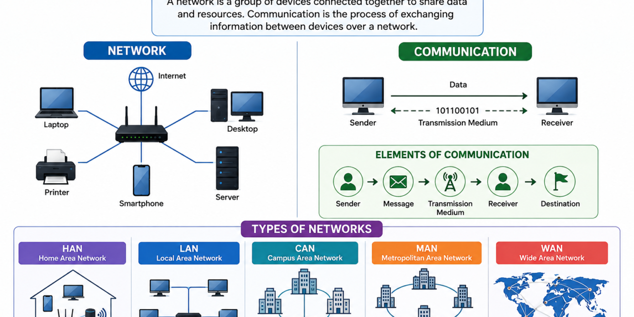
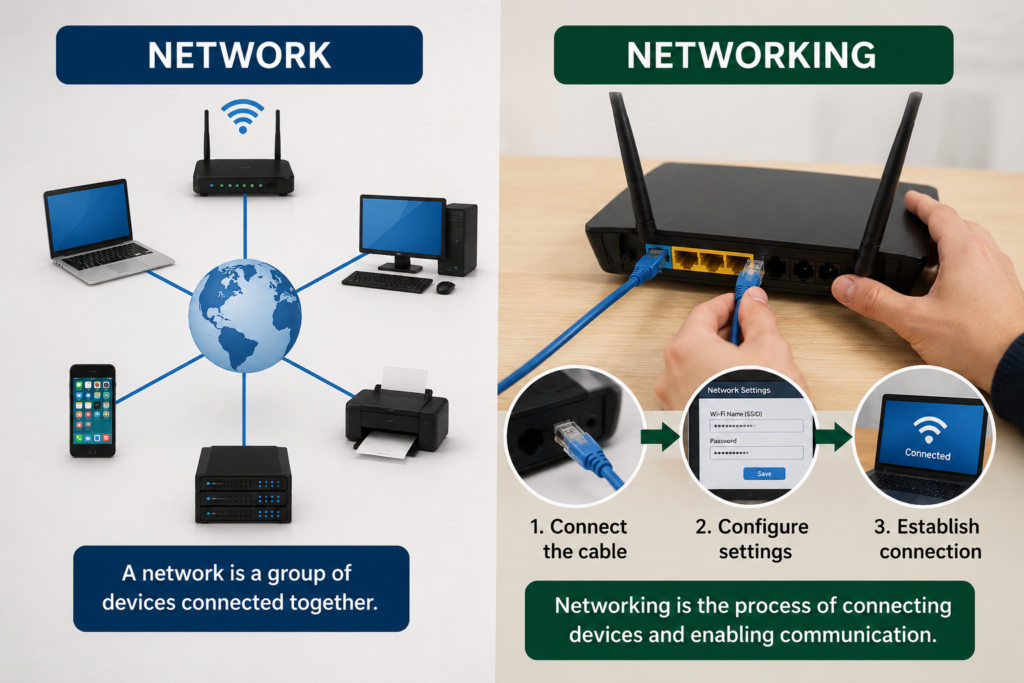
A network is a group of two or more devices that are connected so they can share information and communicate with each other. These devices can be computers, mobile phones, printers, sensors, or microcontrollers. A network allows data to move from one device to another quickly and easily.
Networks can be connected using wires (wired network) or without wires using technologies like Wi-Fi or Bluetooth (wireless network). They are used in homes, schools, offices, and industries to share files, access the internet, and control devices. A small network may connect only a few devices, while a large network can connect millions of devices around the world.
In embedded systems and IoT projects, a network helps microcontrollers and sensors send data to other devices or cloud platforms. For example, an ESP32 connected to Wi-Fi can send temperature and humidity data from a DHT11 sensor to ThingSpeak, where the information can be viewed on a mobile app or computer.What is

What is Networking?
Networking is the process of connecting two or more devices so they can communicate and exchange data with each other. It allows devices such as computers, mobile phones, printers, sensors, and microcontrollers to share information, files, and internet connections.
Networking can be done using cables (wired networking) or wireless technologies like Wi-Fi and Bluetooth. It is widely used in homes, schools, offices, and industries to enable communication between devices.
In simple words, networking means making devices work together by connecting them so they can send and receive data. For example, when an ESP32 sends temperature data from a DHT11 sensor to ThingSpeak over Wi-Fi, it is using networking.

Differences between Network and Networking
| Network | Networking |
|---|---|
| 1. A network is a collection of connected devices. | 1. Networking is the process of connecting devices. |
| 2. It is a system of communication. | 2. It is the activity of creating and managing communication. |
| 3. It is the final result after devices are connected. | 3. It is the method used to build the network. |
| 4. It includes devices like computers, phones, routers, and sensors. | 4. It includes configuring devices, cables, Wi-Fi, and protocols. |
| 5. It allows devices to share data and resources. | 5. It enables devices to communicate and exchange data. |
| 6. It can be wired or wireless. | 6. It involves setting up wired or wireless connections. |
| 7. Example: A home Wi-Fi network. | 7. Example: Connecting a laptop to the home Wi-Fi. |
| 8. It is a noun (a thing). | 8. It is a verb/process (an activity). |
| 9. Its main purpose is communication between devices. | 9. Its main purpose is to establish and maintain the communication. |
What is communication?
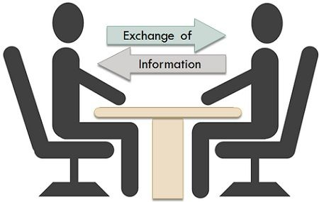
Communication is the process of sharing or exchanging information, ideas, thoughts, or messages between two or more people or devices. The purpose of communication is to ensure that the information is understood correctly by the receiver. Communication can take place through speaking, writing, gestures, images, or electronic signals.
Communication can be done in different ways, such as verbal communication (speaking), written communication (letters, emails, messages), non-verbal communication (body language, facial expressions, and hand gestures), and digital communication using computers, mobile phones, and the internet. Effective communication helps people work together, solve problems, and make better decisions.
In computer networks, communication refers to the exchange of data between connected devices. Computers, smartphones, sensors, and microcontrollers communicate through wired or wireless networks using communication protocols. This allows devices to share files, send messages, access the internet, and transfer information efficiently.
In IoT and embedded systems, communication plays an important role by allowing sensors and microcontrollers to send data to cloud platforms or mobile applications. For example, an ESP32 can send temperature and humidity data from a DHT11 sensor to ThingSpeak through Wi-Fi, where the data can be viewed on a computer or smartphone. This demonstrates successful communication between devices over a network.
What is Networking and Communication
Networking and communication are closely related concepts in computer systems and IoT. Networking is the process of connecting two or more devices so they can communicate and share data. Communication is the exchange of information between those connected devices. In simple words, networking creates the connection, while communication transfers the information.
Networking can be done through wired connections such as Ethernet cables or wireless technologies like Wi-Fi and Bluetooth. Once the devices are connected, communication takes place by sending and receiving data using communication protocols. This enables devices to share files, access the internet, and exchange information quickly and securely.
In embedded systems and IoT applications, networking and communication play a vital role. Microcontrollers, sensors, and cloud platforms work together through a network to exchange data. For example, an ESP32 connected to Wi-Fi sends temperature and humidity data from a DHT11 sensor to ThingSpeak, where the information can be viewed on a mobile application or computer. This demonstrates successful networking and communication between devices.

Basics of Networking and Communication:
Networking and communication involve connecting two or more devices so they can exchange information and share resources. A network consists of interconnected devices such as computers, sensors, PLCs, controllers, and communication equipment like Ethernet switches. These devices communicate through wired or wireless media, including cables, telephone lines, radio waves, satellites, or infrared signals. Networking enables the sharing of files, printers, internet access, and other resources, making communication between devices fast and efficient. The Internet is the largest example of a network, connecting millions of devices worldwide and allowing them to communicate with each other.
1. LAN (Local Area Network)
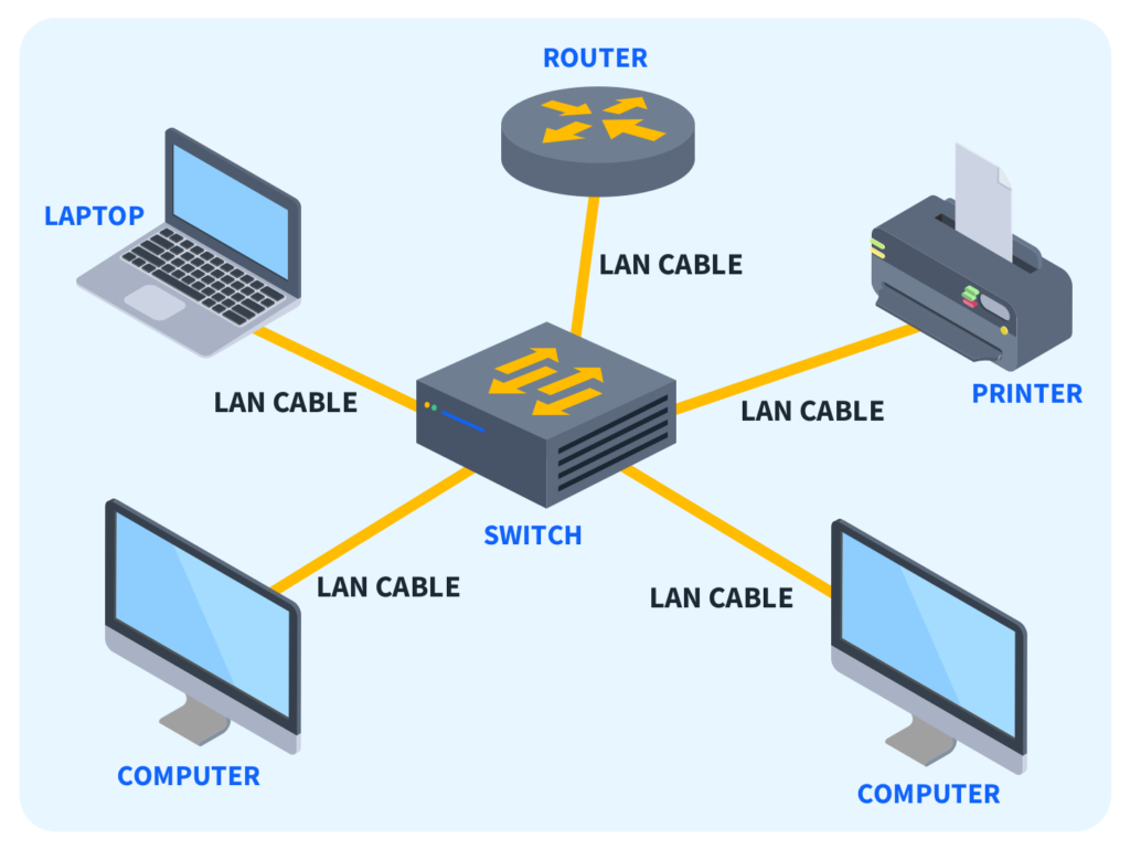
A Local Area Network (LAN) is a network that connects computers and other devices within a small area, such as a home, school, office, or laboratory. It allows devices to share data, files, printers, and an internet connection quickly and securely. LAN usually uses Ethernet cables or Wi-Fi to connect devices.
For example, in a computer lab, all the computers connected to the same Wi-Fi router or network form a LAN. This makes it easy for users to communicate, share files, and access shared resources. LAN is fast, reliable, and commonly used in places where devices are located close to each other.
2.WAN (Wide Area Network)
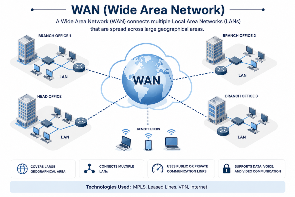
A Wide Area Network (WAN) is a network that connects computers and devices over a large geographical area, such as different cities, states, or countries. It links multiple Local Area Networks (LANs) together, allowing people to communicate and share information even when they are far apart. WAN uses communication technologies such as telephone lines, fiber-optic cables, satellites, and the internet.
The Internet is the best example of a WAN because it connects millions of computers and networks around the world. Banks, multinational companies, schools, and government organizations use WAN to connect their offices in different locations. WAN makes long-distance communication and data sharing possible.
3. MAN (Metropolitan Area Network)
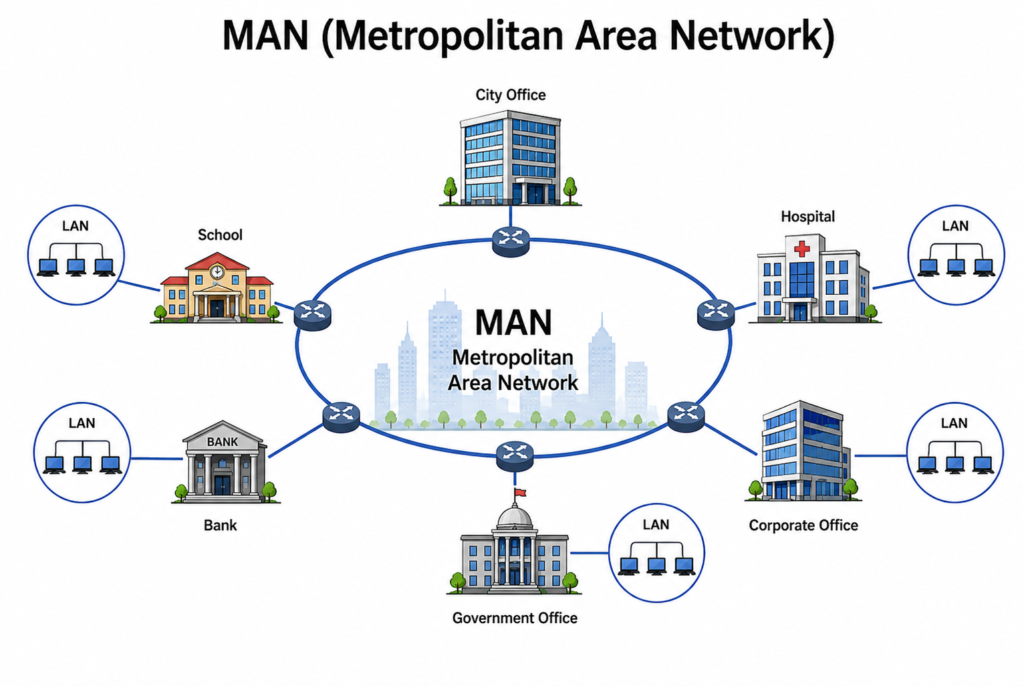
A Metropolitan Area Network (MAN) is a network that connects computers and devices across a city or a large town. It is larger than a Local Area Network (LAN) but smaller than a Wide Area Network (WAN). MAN is used to connect multiple buildings, offices, schools, or colleges within the same city.
For example, a university with several campuses in the same city can use a MAN to connect all its campuses. Internet service providers and large organizations also use MAN to provide fast communication and data sharing across different locations within a city. It offers high-speed connectivity over a wider area than a LAN.
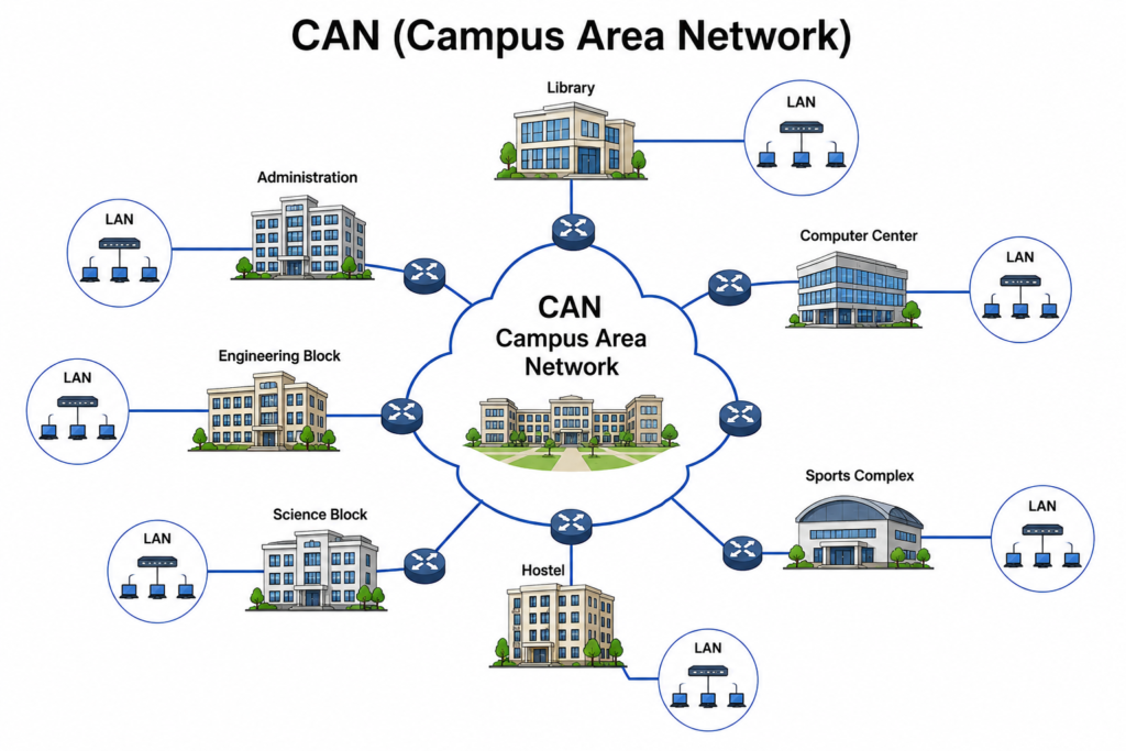
4.CAN (Campus Area Network)
A Campus Area Network (CAN) is a network that connects multiple buildings within a limited area, such as a college campus, university, hospital, or company campus. It is larger than a Local Area Network (LAN) but smaller than a Metropolitan Area Network (MAN). CAN allows different departments or buildings to share data, internet access, printers, and other resources.
For example, a university may connect its library, classrooms, laboratories, and administrative offices through a Campus Area Network. This enables students and staff to communicate, access shared files, and use the same network services efficiently across the entire campus.
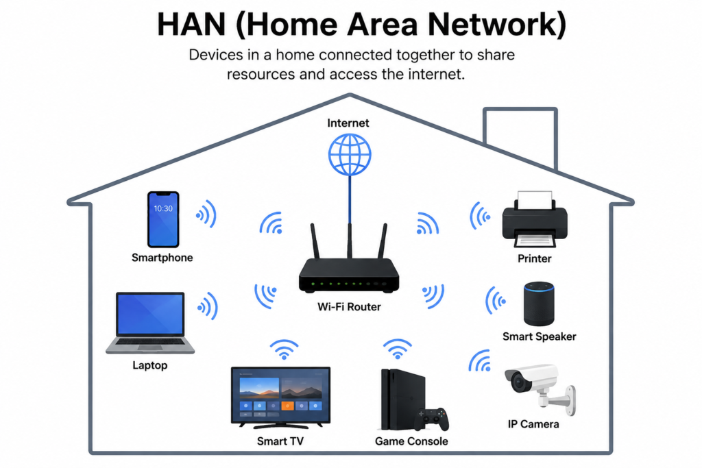
5.HAN (Home Area Network)
A Home Area Network (HAN) is a network that connects different electronic devices inside a home. It allows devices such as smartphones, laptops, smart TVs, printers, Wi-Fi routers, and smart home devices to communicate with each other and share resources like the internet, files, and printers.
HAN usually covers a small area, such as a house or apartment, and mainly uses Wi-Fi or Ethernet cables for communication. It is simple to set up, affordable, and helps family members use multiple devices together through a single internet connection.
Differences Between the Networks
| Network | Full Form | Coverage Area | Used In |
|---|---|---|---|
| HAN | Home Area Network | A single home or apartment | Smart home, home Wi-Fi |
| LAN | Local Area Network | One room, office, or building | School, office, computer lab |
| CAN | Campus Area Network | Multiple buildings in one campus | College, university, factory |
| MAN | Metropolitan Area Network | A city or metropolitan area | City-wide offices, banks, government organizations |
| WAN | Wide Area Network | Countries or worldwide | Internet, multinational companies |
Embedded Networking
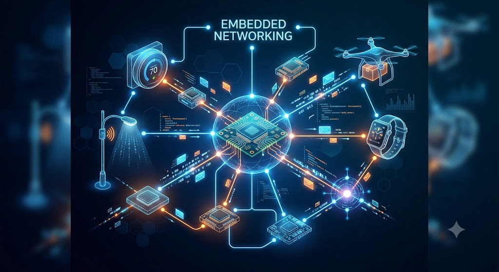
Embedded Networking is the communication between embedded systems or smart devices so they can exchange data and work together. An embedded system is a device designed to perform a specific task, such as a smart washing machine, traffic signal, medical monitor, security camera, or automobile control system. These devices communicate using wired or wireless technologies like UART, I²C, SPI, Ethernet, Wi-Fi, Bluetooth, or CAN bus.
Embedded networking helps devices share information, monitor sensors, and control other devices automatically. It is widely used in smart homes, industrial automation, healthcare, automobiles, and Internet of Things (IoT) applications. By connecting embedded devices through a network, systems become more efficient, reliable, and capable of performing tasks without continuous human intervention.
In simple terms, embedded networking allows smart electronic devices to communicate with each other to perform specific functions efficiently. For example, in a smart home, a motion sensor can send a signal to an embedded controller, which then turns on the lights automatically when someone enters the room.
Types Of Communication
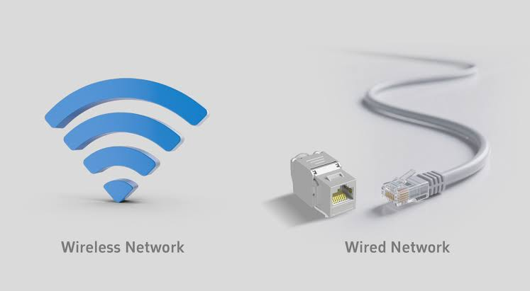
1. Wire
Wired communication is a method of transmitting data between two or more devices using physical cables or wires. It provides a direct and stable connection, making it reliable for transferring data with high speed and low interference. Common cables used in wired communication include Ethernet cables, USB cables, and serial communication cables.
Wired communication is widely used in computers, embedded systems, industrial automation, and networking applications. It is preferred when secure, fast, and uninterrupted communication is required. Common wired communication protocols include UART, SPI, I²C, CAN, and Ethernet.
2. Wireless
Wireless communication is a method of transmitting data between two or more devices without using physical cables. It uses radio waves, infrared, or other wireless signals to send and receive information. This allows devices to communicate over short or long distances while providing greater flexibility and mobility.
Wireless communication is widely used in smartphones, laptops, smart home devices, embedded systems, and IoT applications. It is easy to install and enables devices to connect without wires. Common wireless communication technologies include Wi-Fi, Bluetooth, Zigbee, NFC, LoRa, and cellular networks such as 4G and 5G.
Information about UART, SPI, I2C & IP Address
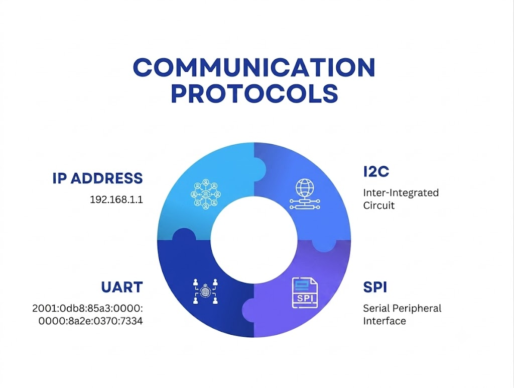
1.URAT (Universal Asynchronous Receiver-Transmitter)
UART (Universal Asynchronous Receiver-Transmitter) is a simple communication method used to exchange data between two electronic devices, such as a microcontroller and a computer, sensor, or another microcontroller. It sends data one bit at a time using two communication wires: TX (Transmit) for sending data and RX (Receive) for receiving data. Since UART is asynchronous, it does not require a separate clock signal for communication.
UART is widely used because it is easy to connect and program. Both devices must be set to the same communication speed (called the baud rate), such as 9600 or 115200 bits per second, for data to be transmitted correctly. It is commonly used for debugging, uploading programs to microcontrollers, communicating with GPS modules, Bluetooth modules, and many other embedded system devices.
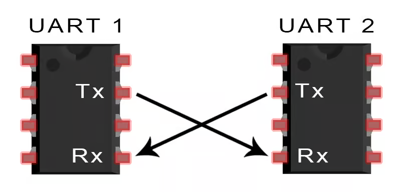
TX– TX (Transmit) is the UART pin used to send data from one device to another.
RX-RX (Receive) is the UART pin used to receive data from another device.
2. IC (Inter-Integrated Circuit)
I²C (Inter-Integrated Circuit) is a communication protocol used to connect a microcontroller with multiple electronic devices such as sensors, displays, memory chips, and other modules. It uses only two communication wires: SDA (Serial Data) for sending and receiving data, and SCL (Serial Clock) for synchronizing the communication. This makes I²C simple and reduces the number of wires needed.
In I²C communication, one device acts as the master, which controls the communication, while the other devices act as slaves. Each slave device has a unique address, allowing the master to communicate with multiple devices using the same two wires. I²C is widely used in embedded systems because it is easy to connect many devices, saves microcontroller pins, and provides reliable communication.
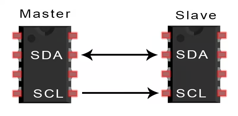
SDA (Serial Data): Transfers data.
SCL (Serial Clock): Provides the clock signal.
3. SPI (Serial Peripheral Interface)
SPI (Serial Peripheral Interface) is a fast communication protocol used to connect a microcontroller with devices such as sensors, displays, memory cards, and other peripherals. It transfers data between devices using four communication lines: MOSI (Master Out Slave In), MISO (Master In Slave Out), SCK (Serial Clock), and CS/SS (Chip Select). The clock signal keeps the communication synchronized, allowing data to be transferred quickly.
In SPI communication, one device acts as the master and controls the communication, while the other devices act as slaves. The master selects the required slave device using the Chip Select (CS) pin before sending or receiving data. SPI is widely used in embedded systems because it provides high-speed communication, supports full-duplex data transfer (sending and receiving data at the same time), and is reliable for connecting multiple peripheral devices.
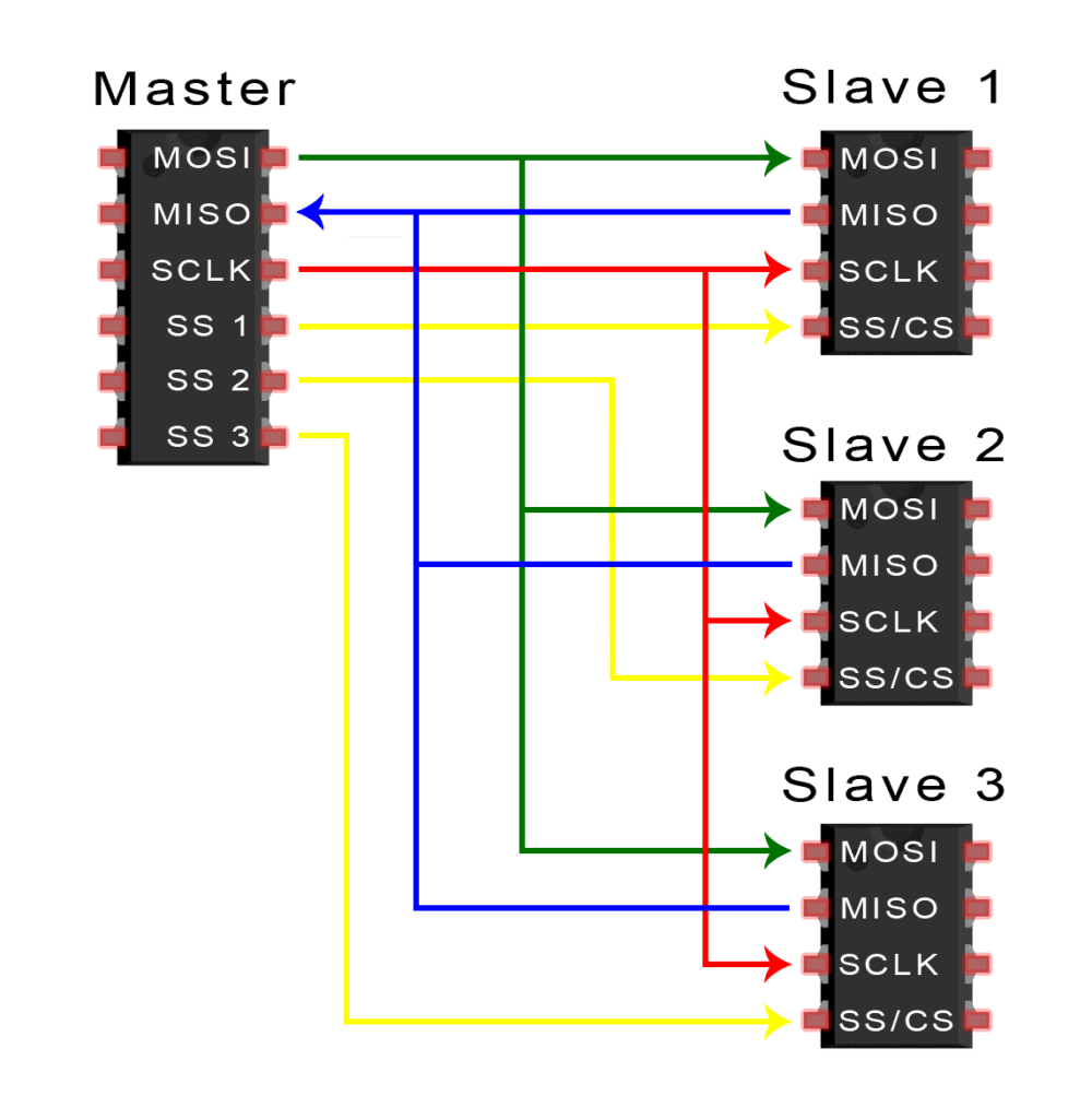
- MOSI (Master Out Slave In): Sends data from the master device to the slave device.
- MISO (Master In Slave Out): Sends data from the slave device to the master device.
- SCLK (Serial Clock): Provides the clock signal to synchronize data transfer between devices.
- CS/SS (Chip Select/Slave Select): Selects the slave device that the master wants to communicate with.
4. IP Address (Internet Protocol)
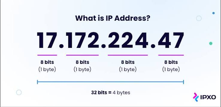
An IP (Internet Protocol) address is a unique number assigned to every device connected to a network or the Internet. It helps identify a device and allows it to send and receive data with other devices on the network.
There are two main types of IP addresses: IPv4 and IPv6. An IPv4 address consists of four numbers separated by dots (for example, 192.168.1.1), while an IPv6 address is longer and uses hexadecimal numbers. IP addresses are essential for communication between computers, smartphones, servers, and other network devices over the Internet.
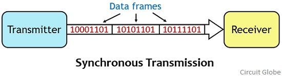
Synchronous Serial Communication
Synchronous serial communication is a method of transmitting data in which the sender and receiver are synchronized using a common clock signal. The clock ensures that both devices know exactly when each bit of data is sent and received, allowing communication to occur accurately and efficiently. Since the timing is controlled by the clock, there is no need for additional start and stop bits for each data byte.
In synchronous communication, data is transferred continuously in a stream of bits at regular intervals. The shared clock signal keeps both devices perfectly synchronized, resulting in faster data transfer and fewer transmission errors. This makes it suitable for applications where high-speed and reliable communication is required.
Synchronous serial communication is widely used in embedded systems, microcontrollers, sensors, memory devices, and communication modules. Common protocols that use this method include SPI (Serial Peripheral Interface) and I²C (Inter-Integrated Circuit). These protocols enable efficient communication between a microcontroller and multiple peripheral devices.
The main advantages of synchronous serial communication are high speed, improved reliability, and efficient use of bandwidth. However, it requires additional hardware or wiring for the clock signal, making the circuit slightly more complex than asynchronous communication. Despite this, it is preferred in many electronic systems where fast and accurate data transfer is essential.
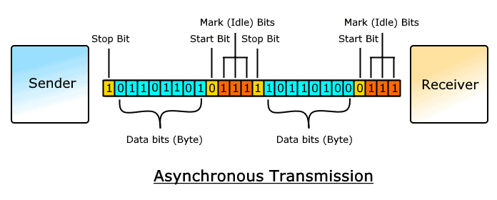
Asynchronous Serial Communication
Asynchronous serial communication is a method of sending data between two devices one bit at a time without using a shared clock signal. Instead of a clock, both the sender and receiver agree on the same communication speed (called the baud rate). Each data byte is sent with a start bit and one or more stop bits, which help the receiver identify the beginning and end of each data packet.
This type of communication is simple, reliable, and widely used in embedded systems and microcontrollers because it requires only two communication lines: TX (Transmit) and RX (Receive). A common example of asynchronous serial communication is UART, which is used for communication between microcontrollers, computers, sensors, and modules such as GPS and Bluetooth devices.
Difference Between Synchronous & Asynchronous
| Synchronous Communication | Asynchronous Communication |
|---|---|
| 1. Uses a common clock signal between sender and receiver. | 1. Does not use a common clock signal. |
| 2. Data is transmitted continuously in blocks or frames. | 2. Data is transmitted one byte or character at a time. |
| 3. No start and stop bits are required. | 3. Each data byte uses start and stop bits. |
| 4. Faster data transfer due to continuous transmission. | 4. Slower because of extra start and stop bits. |
| 5. More efficient for transferring large amounts of data. | 5. Better suited for transferring small amounts of data. |
| 6. Requires an additional clock line. | 6. Requires only TX (Transmit) and RX (Receive) lines. |
| 7. More complex hardware and circuit design. | 7. Simpler hardware and easier to implement. |
| 8. Timing is controlled by the shared clock signal. | 8. Timing is controlled by matching the baud rate. |
| 9. Examples: SPI, I²C. | 9. Example: UART. |
| 10. Higher communication speed and accuracy. | 10. Lower speed but simple and reliable for many applications. |
| 11. Commonly used in high-speed embedded systems and memory | 11. Commonly used for serial communication between microcontrollers, computers, GPS, Bluetooth, and sensors. |
| 12. Better synchronization during long data transfers. | 12. Synchronization is achieved separately for each transmitted byte using start and stop bits. |
Developing a Wired Communication System Using ESP32-C3
Connecting the ESP32-C3 Board
First, I connected two ESP32-C3 boards for wired serial communication. I connected the TX pin of the first ESP32-C3 to the RX pin of the second ESP32-C3, and the RX pin of the first ESP32-C3 to the TX pin of the second ESP32-C3. I also connected the GND of both boards together. This TX-to-RX and RX-to-TX connection allows the two boards to exchange data.
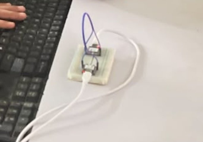
Step 2: Writing the Communication CodeNext, I opened the Arduino IDE and wrote the code for both ESP32-C3 boards. The first board was programmed to send data through its TX pin, while the second board was programmed to receive the data through its RX pin. I prepared the programs according to the TX and RX connections.
Step 3: Uploading the CodesAfter completing the programs, I uploaded the required code to each ESP32-C3 separately using the Arduino IDE. I selected the correct board and port for each ESP32-C3 and checked that the code was uploaded successfully.
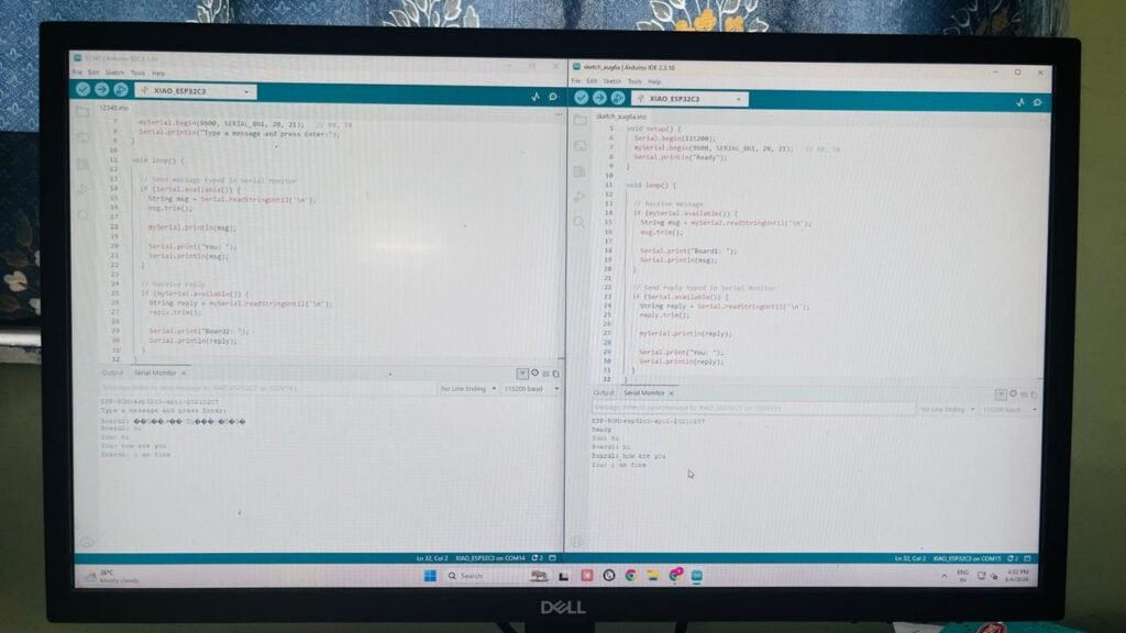
Step 4: Testing the Wired CommunicationFinally, I tested the communication by sending data from the first ESP32-C3 to the second one. The data transmitted through TX was received through RX, and the two boards successfully.
Code I Use :-
Board 1
Board 2
Developing an LED ON/OFF Control System Using Bluetooth.
Step 1: Setting Up the Arduino and Bluetooth
First, I set up the Arduino board, Bluetooth module, and LED on a breadboard. I connected the LED to the required digital pin of the Arduino and connected the Bluetooth module to the Arduino for wireless communication. I checked all the power, ground, TX, and RX connections before starting the programming.
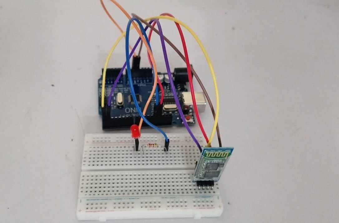
Step 2: Writing the Arduino CodeNext, I opened the Arduino IDE and wrote the program to control the LED using Bluetooth commands. I programmed the Arduino so that when it receives an ON command, the LED turns on, and when it receives an OFF command, the LED turns off.
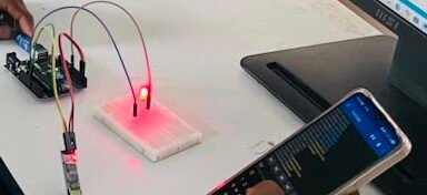
Step 3: Uploading and Connecting BluetoothAfter completing the code, I selected the correct Arduino board and COM port and uploaded the program. Then, I connected my mobile phone to the Bluetooth module. Once the Bluetooth connection was established, I was able to send commands from the phone to the Arduino.

Step 4: Testing the LED ON/OFF Control
Finally, I tested the project by sending ON and OFF commands through Bluetooth. When I sent the ON command, the Arduino received it and switched the LED on. When I sent the OFF command, the LED turned off. This showed that the Bluetooth communication and LED control were working successfully
Code :-
#include <SoftwareSerial.h>

SoftwareSerial BT(10, 11);   // RX, TX

const int ledPin = 13;
char command;

void setup() {
  pinMode(ledPin, OUTPUT);
  digitalWrite(ledPin, LOW);

  Serial.begin(9600);
  BT.begin(9600);

  Serial.println("Bluetooth LED Control Ready");
}

void loop() {
  if (BT.available()) {
    command = BT.read();

    Serial.print("Received: ");
    Serial.println(command);

    if (command == '1') {
      digitalWrite(ledPin, HIGH);
      BT.println("LED ON");
    }

    if (command == '0') {
      digitalWrite(ledPin, LOW);
      BT.println("LED OFF");
    }
  }
}