Introduction
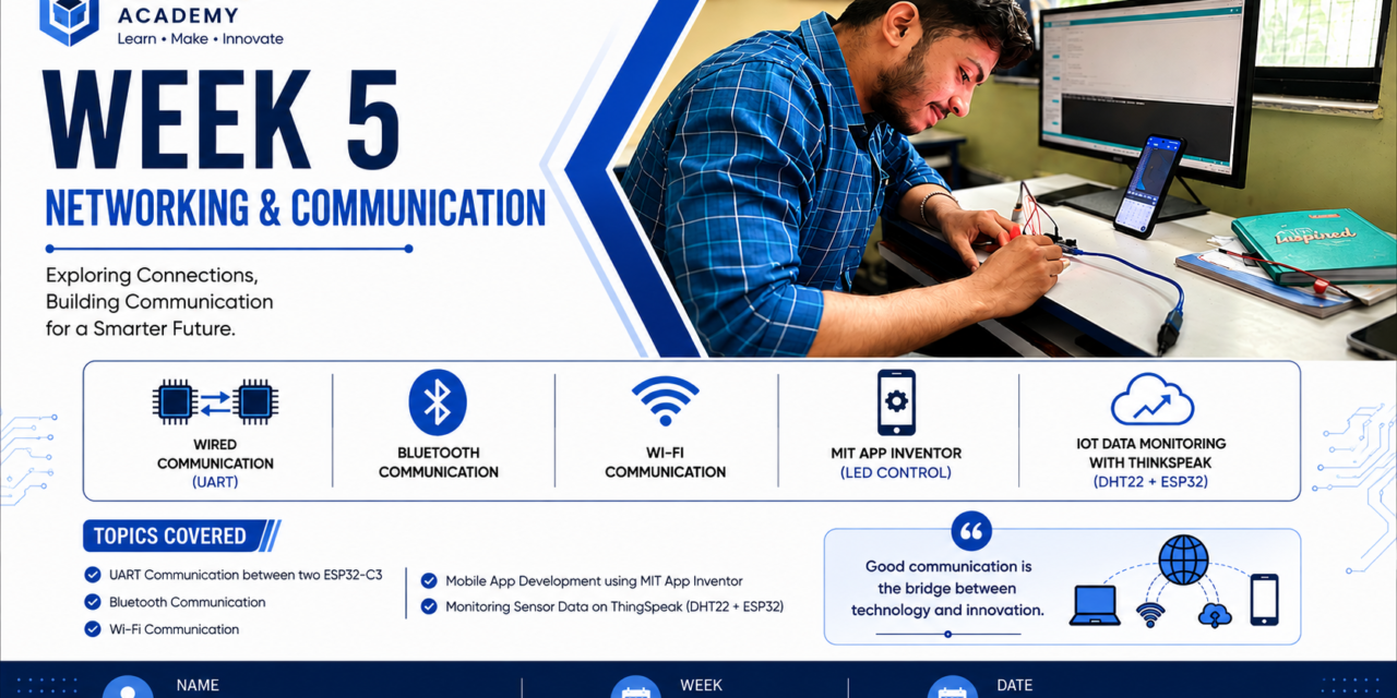
In Week 5, I learned about Networking and Communication in embedded systems. I studied how different electronic devices communicate with each other and exchange data using various communication protocols.
During this week, I learned the basic concepts of data, communication, networking, serial and parallel communication, synchronous and asynchronous communication, and different communication protocols such as UART, I²C, SPI, One-Wire, Bluetooth, and Wi-Fi.
For the practical work, I performed communication between two ESP32 boards as part of the group assignment. I also created a mobile application using MIT App Inventor to control an LED wirelessly and built a temperature and humidity monitoring system using ESP32, ThingSpeak, and MIT App Inventor. This week helped me understand both the theory and practical implementation of communication in embedded systems.
Introduction to Networking and Communication
Networking and communication are essential concepts in embedded systems and the Internet of Things (IoT). They enable electronic devices to exchange data and work together efficiently. Communication can take place through wired or wireless connections using different communication protocols. These protocols define how data is transmitted, received, and interpreted between devices. In embedded systems, networking and communication are widely used in applications such as home automation, industrial control, smart agriculture, healthcare, and environmental monitoring.
What is Data?
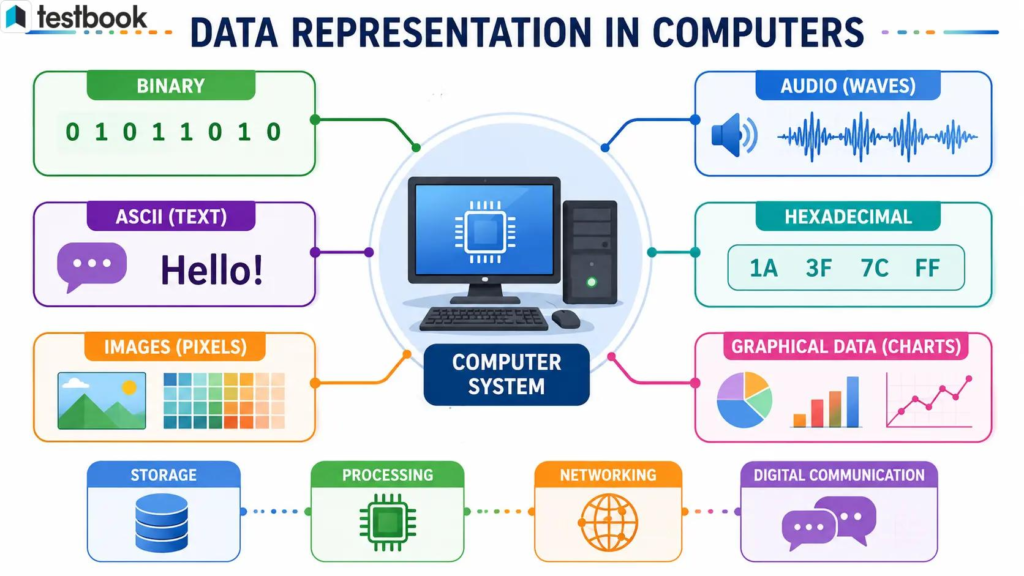
Data is a collection of information that can be processed, stored, or transmitted between devices. In embedded systems, data is generated by sensors, user inputs, or other electronic devices. This data can be in the form of numbers, text, characters, images, or signals. Microcontrollers process this data and communicate it to other devices for monitoring, control, or decision-making.
Examples:
- Temperature reading: 30°C
- Humidity value: 65%
- LED status: ON/OFF
- Distance measured by an ultrasonic sensor: 25 cm
What is Communication?
Communication is the process of exchanging data or information between two or more devices. In embedded systems, communication allows microcontrollers, sensors, actuators, and other electronic devices to send and receive data. This enables devices to work together and perform specific tasks efficiently.
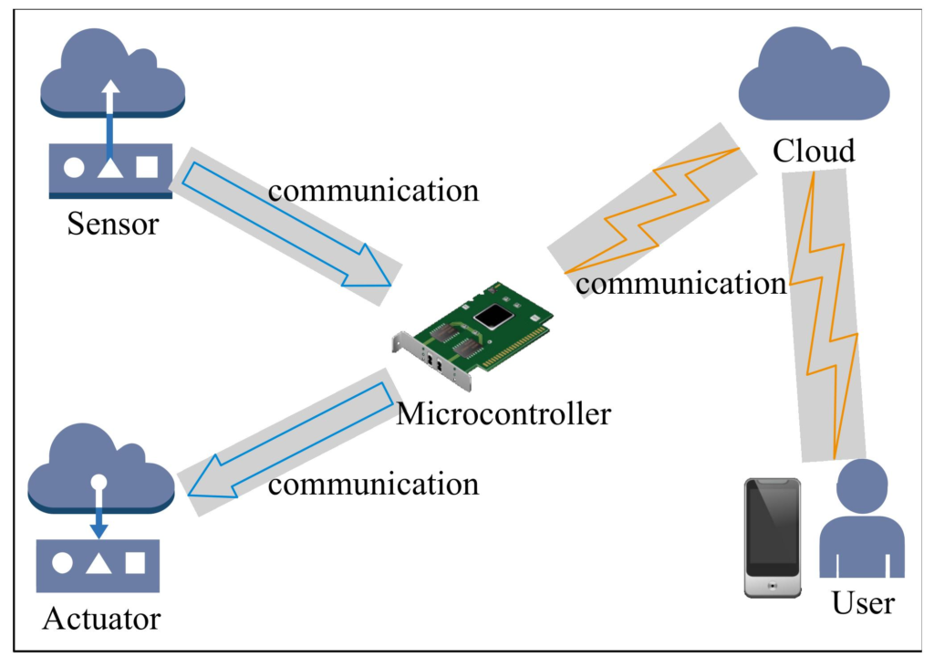
Communication can be carried out through wired methods (such as UART, I²C, and SPI) or wireless methods (such as Bluetooth and Wi-Fi).
Example:
An ESP32 reads temperature from a DHT11 sensor and sends the data to a mobile application through Wi-Fi for monitoring.
What is Networking?
Networking is the process of connecting two or more electronic devices so they can communicate and exchange data. The connected devices form a network, allowing them to share information and resources efficiently. Networking can be established using wired connections, such as Ethernet cables, or wireless technologies, such as Wi-Fi and Bluetooth.
In embedded systems and the Internet of Things (IoT), networking enables microcontrollers, sensors, computers, mobile devices, and cloud platforms to communicate with each other. This allows devices to monitor, control, and exchange data in real time.
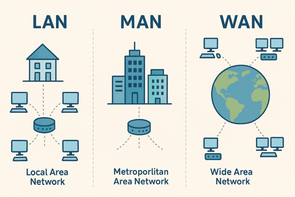
Types of Networks
- LAN (Local Area Network): Connects devices within a limited area such as a home, office, or laboratory.
- MAN (Metropolitan Area Network): Connects devices across a city or large campus.
- WAN (Wide Area Network): Connects devices over large geographical areas, including the Internet.
Advantages of Networking
- Enables data sharing between devices.
- Supports real-time communication.
- Allows remote monitoring and control.
- Improves efficiency and automation.
- Makes resource sharing easier.
Applications
- Smart home automation
- Industrial automation
- IoT systems
- Smart agriculture
- Healthcare monitoring
- Environmental monitoring
What is a Communication Protocol?
A communication protocol is a set of rules that defines how data is transmitted and received between electronic devices. It ensures that devices communicate in a reliable and organized manner by specifying the format, timing, and method of data exchange. Different protocols are used depending on the application and communication requirements.
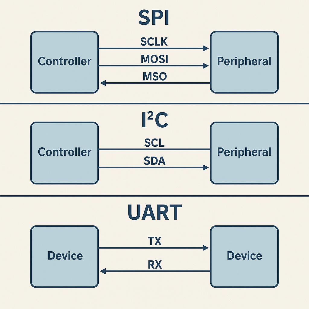
Common Communication Protocols:
- UART (Universal Asynchronous Receiver/Transmitter)
- I²C (Inter-Integrated Circuit)
- SPI (Serial Peripheral Interface)
- One-Wire
- Bluetooth
- Wi-Fi
IoT (Internet of Things)
IoT (Internet of Things) is a technology that connects physical devices such as sensors, microcontrollers, and machines to the internet or a network. These connected devices can collect, exchange, and process data without continuous human interaction.
In IoT systems, devices use communication technologies like Wi-Fi, Bluetooth, and other network protocols to send and receive data. Microcontrollers such as ESP32 are commonly used in IoT applications because they have built-in wireless communication capabilities.
Applications of IoT
- Smart home automation
- Smart agriculture
- Industrial monitoring
- Healthcare monitoring
- Weather monitoring systems
- Remote device control
Advantages of IoT
- Real-time monitoring
- Remote control of devices
- Automation of tasks
- Efficient data collection
- Better decision-making using collected data
Types of Communication
Communication in embedded systems is mainly classified into two types:
Wired Communication
Wired communication transfers data through physical cables or wires. It is generally reliable, fast, and less affected by external interference. Common wired communication protocols include UART, I²C, SPI, and One-Wire.
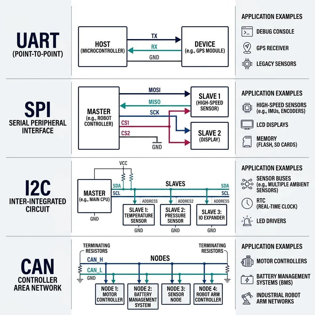
Examples:
- UART
- I²C
- SPI
- One-Wire
Wireless Communication
Wireless communication transfers data without using physical wires. It uses radio waves or electromagnetic signals to exchange information between devices. Wireless communication is widely used in IoT, home automation, and remote monitoring applications.
Examples:
- Wi-Fi
- Bluetooth
- Zigbee
- LoRa
Data Transmission Methods
Data can be transmitted between devices using two methods: Serial Communication and Parallel Communication.
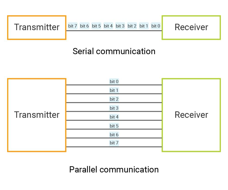
Serial Communication
Serial communication transfers data one bit at a time through a single communication line. It requires fewer wires, is suitable for long-distance communication, and is commonly used in embedded systems.
Examples:
- UART
- I²C
- SPI
- One-Wire
Advantages
- Requires fewer wires
- Suitable for long-distance communication
- Simple and cost-effective
Disadvantages
- Slower than parallel communication for transferring large amounts of data
Parallel Communication
Parallel communication transfers multiple bits simultaneously using multiple data lines. It provides higher data transfer speed over short distances but requires more wires.
Examples:
- Communication between a microprocessor and memory
- Parallel LCD interface
- Computer data buses
Advantages
- Faster data transfer
- Multiple bits transmitted at the same time
Disadvantages
- Requires more wires
- Not suitable for long-distance communication due to signal interference
Communication Modes
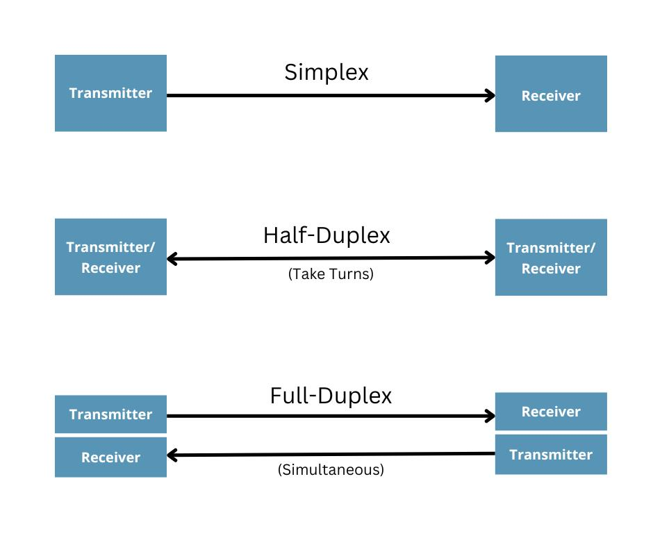
Communication modes define the direction in which data is transmitted between devices. There are three communication modes:
Simplex Communication
In simplex communication, data flows in only one direction. One device acts as the sender, and the other acts as the receiver. The receiver cannot send data back.
Examples:
- Television broadcast
- Keyboard to computer
Half-Duplex Communication
In half-duplex communication, data can flow in both directions, but only one device can transmit at a time. The devices take turns sending and receiving data.
Examples:
- Walkie-talkies
- Two-way radio communication
Full-Duplex Communication
In full-duplex communication, data can be transmitted and received simultaneously. Both devices can communicate at the same time.
Examples:
- Mobile phone calls
- Video calls
- Ethernet communication
Synchronous and Asynchronous Communication
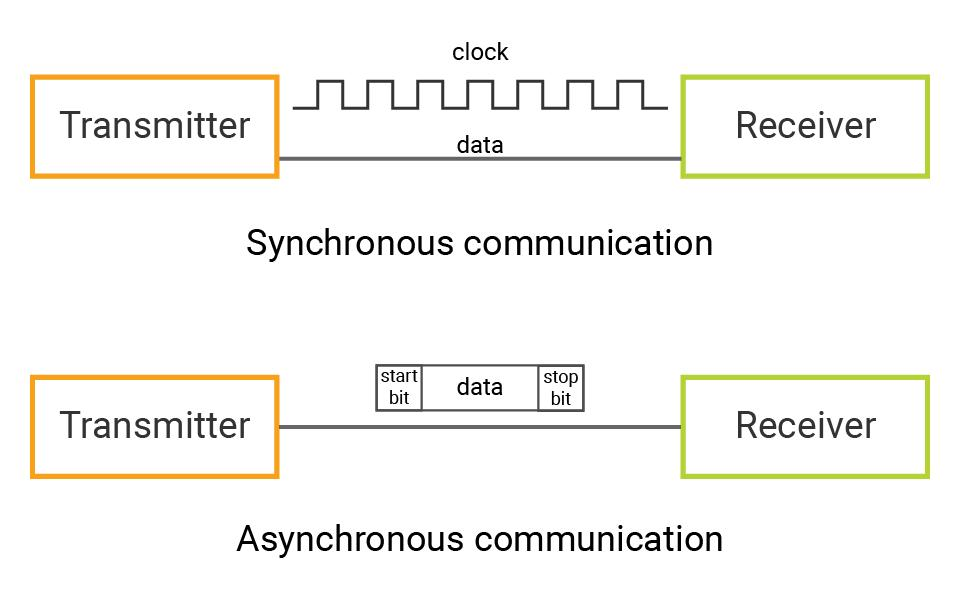
Communication between devices can be classified into Synchronous and Asynchronous communication based on how the data is synchronized during transmission.
Synchronous Communication
In synchronous communication, the sender and receiver use a common clock signal to synchronize data transmission. Since both devices are synchronized, data can be transferred at higher speeds with better efficiency.
Examples:
- SPI
- I²C
Advantages
- High data transfer speed
- Reliable communication
- Suitable for continuous data transmission
Disadvantages
- Requires clock synchronization
- More complex than asynchronous communication
Asynchronous Communication
In asynchronous communication, the sender and receiver do not share a common clock signal. Data is transmitted using start bits and stop bits to indicate the beginning and end of each data packet.
Examples:
- UART
- Serial communication between a computer and a microcontroller
Advantages
- Simple to implement
- No separate clock line required
Disadvantages
- Lower speed due to start and stop bits
- Less efficient for large amounts of data
UART (Universal Asynchronous Receiver/Transmitter)
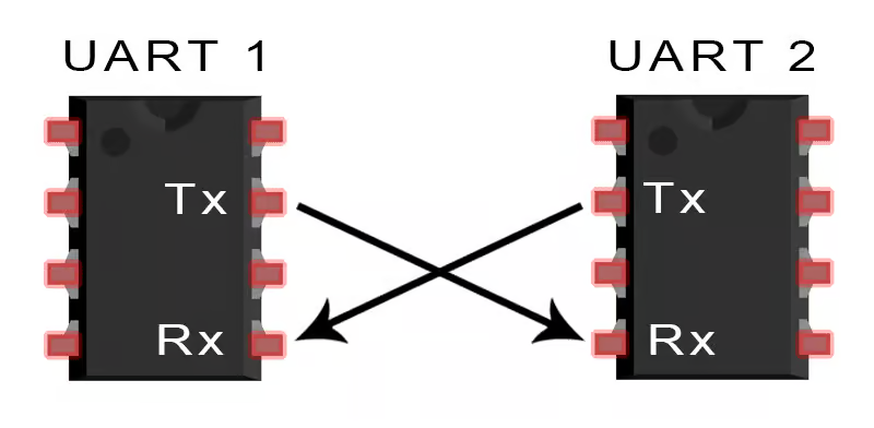
UART (Universal Asynchronous Receiver/Transmitter) is a serial communication protocol used to exchange data between two devices. It is an asynchronous communication protocol, which means it does not require a separate clock signal. Data is transmitted and received through two communication lines: TX (Transmit) and RX (Receive).
Features
- Asynchronous communication
- Uses two data lines: TX and RX
- Supports full-duplex communication
- Simple and easy to implement
- Suitable for communication between two devices
Working
The transmitting device sends data through the TX pin, and the receiving device reads the data through the RX pin. Both devices must be configured with the same baud rate (such as 9600 or 115200 bps) for successful communication.
Applications
- Communication between a computer and a microcontroller
- GPS modules
- Bluetooth modules (HC-05/HC-06)
- GSM modules
- Serial Monitor in Arduino IDE
Advantages
- Simple hardware connection
- Requires only two communication lines
- Suitable for long-distance serial communication
Disadvantages
- Supports communication between only two devices directly
- Slower than SPI for high-speed applications
- No built-in addressing for multiple devices
I²C (Inter-Integrated Circuit)
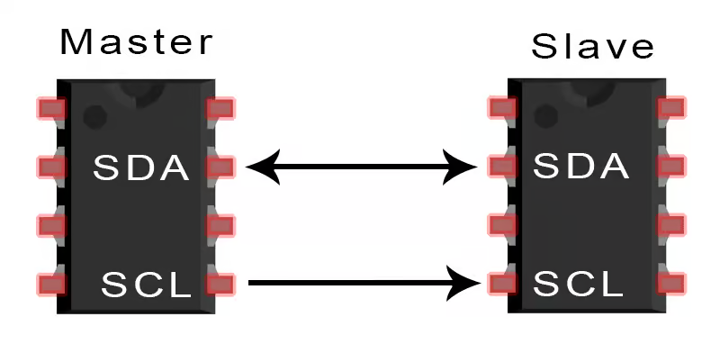
I²C (Inter-Integrated Circuit) is a serial communication protocol used to communicate between multiple devices using only two communication lines. It is a synchronous communication protocol because it uses a clock signal for data transfer. One device acts as the Master, while the others act as Slaves.
Features
- Synchronous communication
- Uses only two wires: SDA (Serial Data) and SCL (Serial Clock)
- Supports multiple devices on the same bus
- Each device has a unique address
- Suitable for short-distance communication
Working
The Master device generates the clock signal and initiates communication. It sends the address of the required Slave device through the SDA line. The addressed slave responds, and data is exchanged between the Master and the selected Slave.
Applications
- OLED Displays
- LCD with I²C Module
- RTC (Real-Time Clock)
- EEPROM
- Temperature and Humidity Sensors
Advantages
- Uses only two wires
- Supports multiple devices
- Easy to connect and expand
Disadvantages
- Slower than SPI
- Suitable only for short-distance communication
- Communication speed decreases as more devices are added
SPI (Serial Peripheral Interface)
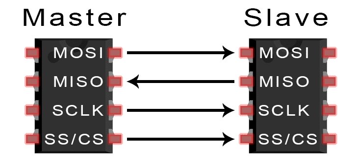
SPI (Serial Peripheral Interface) is a high-speed synchronous serial communication protocol used for communication between a microcontroller and peripheral devices. It uses separate lines for transmitting and receiving data, making it faster than UART and I²C.
Features
- Synchronous communication
- High-speed data transfer
- Full-duplex communication
- Supports one Master and one or more Slave devices
- Uses four communication lines
SPI Pins
- MOSI (Master Out Slave In) – Sends data from Master to Slave
- MISO (Master In Slave Out) – Sends data from Slave to Master
- SCK (Serial Clock) – Clock signal generated by the Master
- CS/SS (Chip Select/Slave Select) – Selects the Slave device for communication
Working
The Master device generates the clock signal through the SCK pin and selects the required Slave using the CS/SS pin. Data is transmitted from the Master through MOSI and received from the Slave through MISO simultaneously.
Applications
- SD Card Modules
- RFID RC522
- TFT and OLED Displays
- Flash Memory
- Sensors requiring high-speed communication
Advantages
- Very fast communication
- Full-duplex data transfer
- Reliable for high-speed applications
Disadvantages
- Requires more wires than UART and I²C
- Each Slave device needs a separate CS/SS pin
- More complex wiring for multiple devices
One-Wire Communication
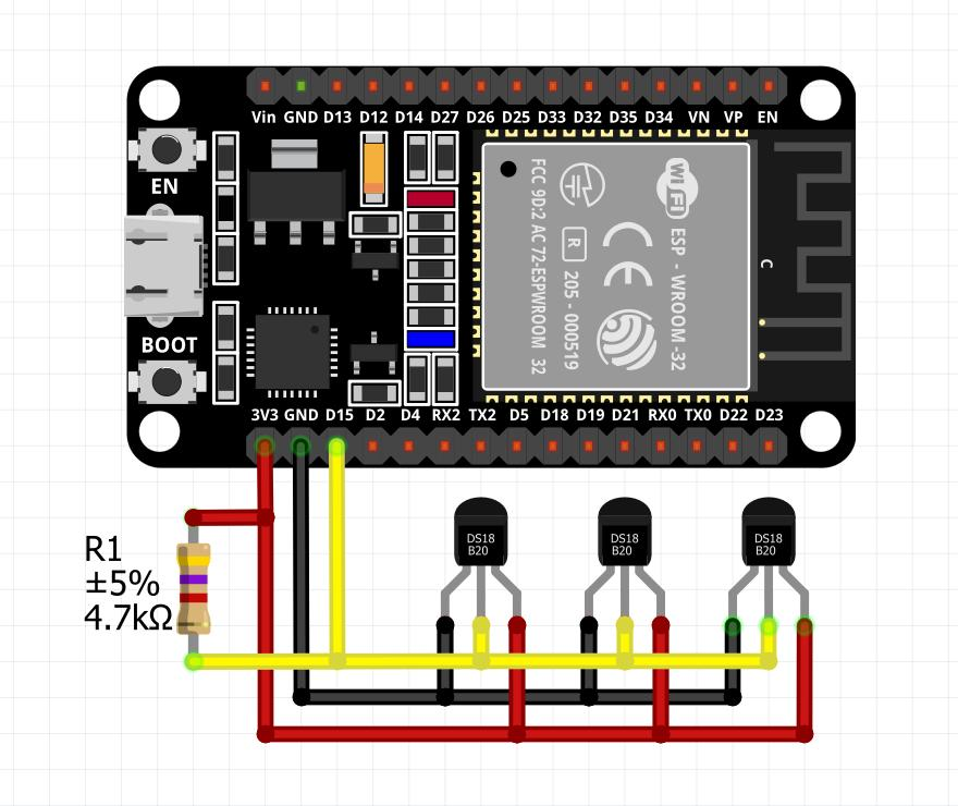
One-Wire is a serial communication protocol that allows data transmission between devices using a single data wire along with a ground connection. It is commonly used for simple communication with sensors and identification devices. Each device connected to the One-Wire bus has a unique 64-bit address, allowing multiple devices to share the same communication line.
Features
- Uses one data line and one ground line
- Serial communication
- Supports multiple devices on the same bus
- Each device has a unique 64-bit address
- Simple wiring
Working
The microcontroller communicates with One-Wire devices through a single data line. It identifies each device using its unique address and exchanges data one device at a time.
Applications
- DS18B20 Temperature Sensor
- iButton Devices
- Digital Identification Systems
Advantages
- Very simple wiring
- Low cost
- Multiple devices can share the same data line
Disadvantages
- Slower than SPI and I²C
- Suitable only for low-speed communication
- Limited communication distance
Bluetooth Communication
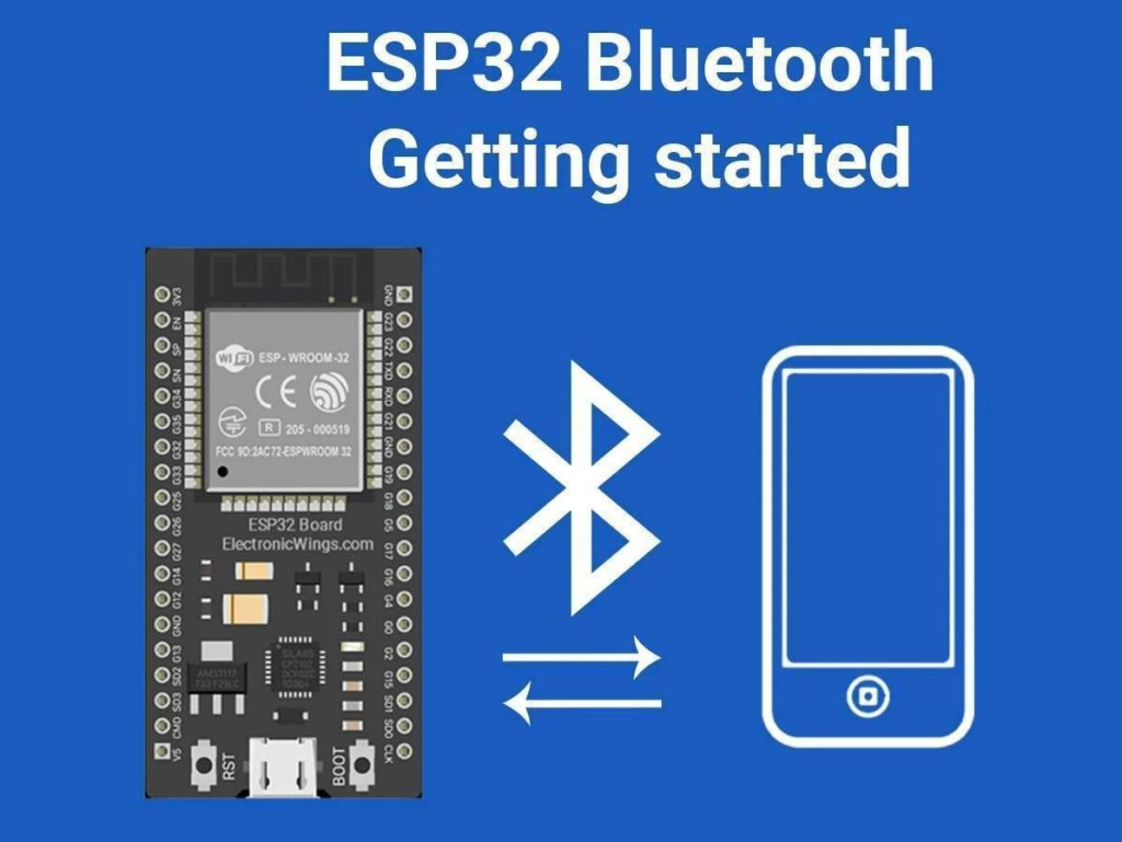
Bluetooth is a wireless communication technology used to exchange data between devices over short distances. It operates in the 2.4 GHz ISM frequency band and does not require an internet connection. Bluetooth is widely used in embedded systems for wireless control and data sharing.
Features
- Wireless communication
- Short-range communication (typically up to 10 meters)
- Low power consumption
- Easy device pairing
- Operates at 2.4 GHz
Working
Bluetooth-enabled devices are paired with each other before communication. Once paired, they can send and receive data wirelessly within the communication range.
Applications
- Wireless speakers and headphones
- Mobile phone accessories
- Smart home devices
- Robot control
- Wireless sensor systems
Advantages
- No cables required
- Low power consumption
- Easy to set up and use
Disadvantages
- Short communication range
- Lower data transfer speed than Wi-Fi
- Performance may be affected by interference from other 2.4 GHz devices
Wi-Fi Communication
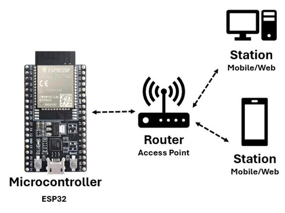
Wi-Fi is a wireless communication technology that allows devices to connect to a local network or the internet. It is widely used in IoT applications because it enables microcontrollers to communicate with mobile applications, cloud platforms, and other devices over a wireless network.
Features
- Wireless communication
- High-speed data transfer
- Internet connectivity
- Supports communication between multiple devices
- Operates on 2.4 GHz and 5 GHz frequency bands
Working
A Wi-Fi-enabled device, such as an ESP32, connects to a Wi-Fi network using the network name (SSID) and password. Once connected, it can send and receive data with other devices on the same network or communicate with cloud services through the internet.
Applications
- IoT devices
- Smart home automation
- Remote monitoring and control
- Weather monitoring systems
- Cloud-based data logging (e.g., ThingSpeak)
Advantages
- High data transfer speed
- Long communication range compared to Bluetooth
- Supports internet-based communication
- Easy integration with cloud platforms and mobile applications
Disadvantages
- Higher power consumption than Bluetooth
- Requires a Wi-Fi network or hotspot
- Performance depends on network signal strength and stability
Comparison of UART, I²C, and SPI
| Feature | UART | I²C | SPI |
|---|---|---|---|
| Communication Type | Serial | Serial | Serial |
| Clock Required | No | Yes | Yes |
| Number of Wires | 2 (TX, RX) | 2 (SDA, SCL) | 4 (MOSI, MISO, SCK, CS) |
| Speed | Medium | Medium | High |
| Number of Devices | 2 | Multiple | Multiple |
| Communication Mode | Full-Duplex | Half-Duplex | Full-Duplex |
| Addressing | No | Yes | No |
| Typical Distance | Short | Short | Short |
| Common Applications | GPS, GSM, Computer Communication | Sensors, OLED, RTC, EEPROM | RFID, SD Card, TFT Display |
Summary
- UART is the simplest communication protocol and is mainly used for communication between two devices.
- I²C uses only two wires and supports communication with multiple devices using unique addresses.
- SPI is the fastest of the three protocols and is preferred for applications that require high-speed data transfer.
Advantages of Networking and Communication
Networking and communication provide an efficient way for electronic devices to exchange data and work together. They are widely used in embedded systems and IoT applications.
Advantages
- Enables data sharing between devices
- Supports real-time monitoring and control
- Reduces manual effort through automation
- Allows wireless communication over a network
- Improves system efficiency and reliability
- Supports remote monitoring and control
- Easy integration with sensors, displays, and cloud platforms
- Enables multiple devices to communicate with each other
- Widely used in smart home, industrial, and IoT applications
Group assignment
Wireless Communication Between Two ESP32 Boards:
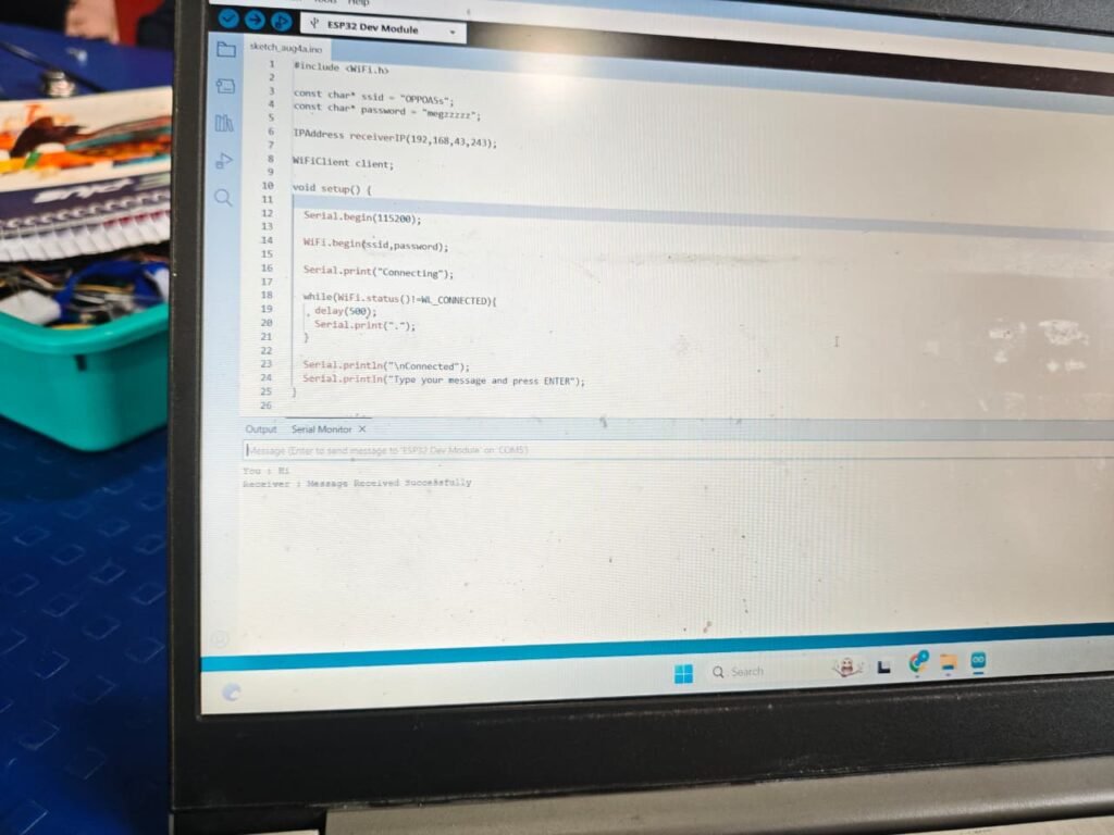
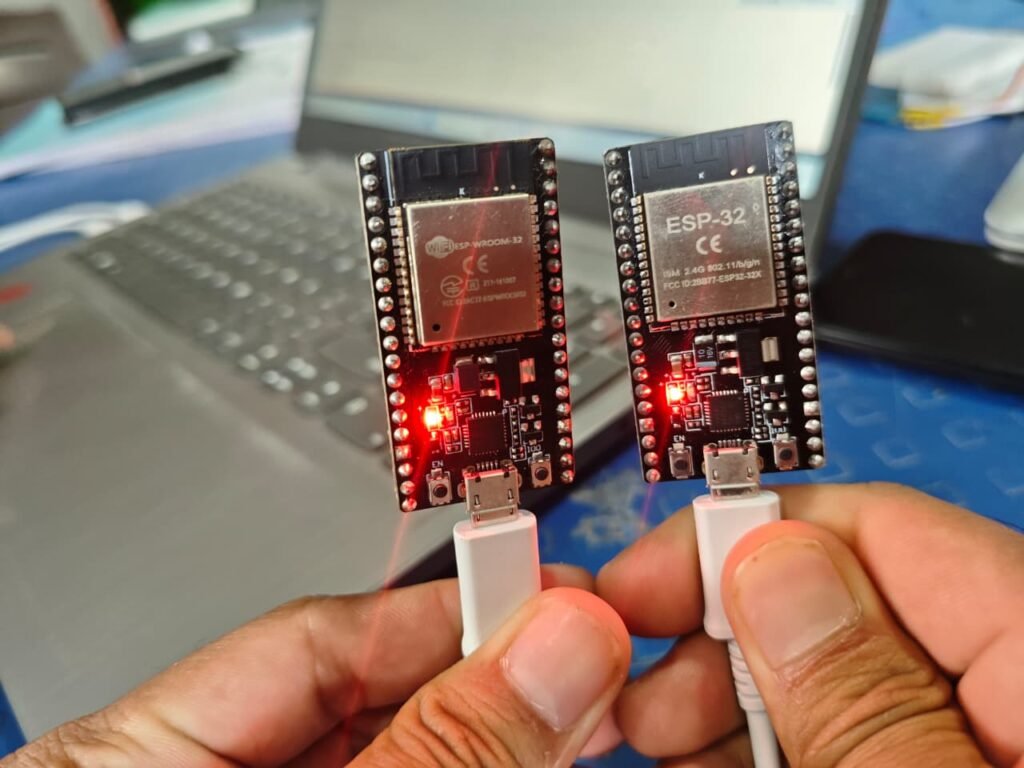
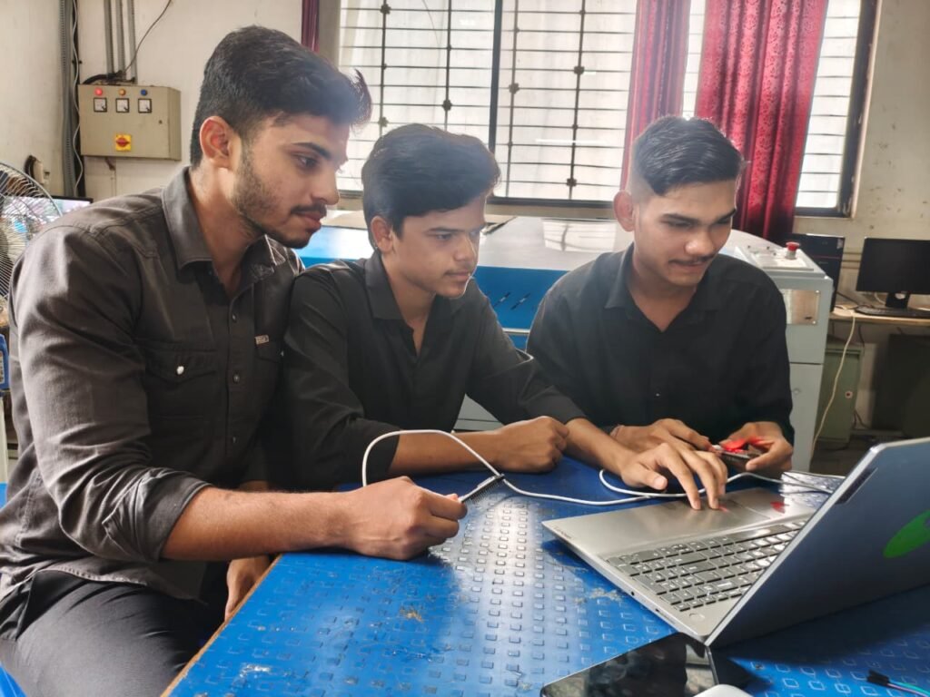
As part of the group assignment, we established communication between two ESP32 development boards using a Wi-Fi network. Both ESP32 boards were connected to the same mobile hotspot, allowing them to communicate with each other over the network. One ESP32 was programmed to send data, while the other received the data. After uploading the programs and connecting both devices to the hotspot, the communication was successfully established, and the transmitted data was received correctly, demonstrating wireless communication between the two ESP32 boards.
Receiver
#include <WiFi.h>

const char* ssid = "YOUR_HOTSPOT_NAME";
const char* password = "YOUR_PASSWORD";

WiFiServer server(80);

void setup() {
  Serial.begin(115200);

  WiFi.begin(ssid, password);
  while (WiFi.status() != WL_CONNECTED) {
    delay(500);
    Serial.print(".");
  }

  Serial.println("\nConnected");
  Serial.println(WiFi.localIP());

  server.begin();
}

void loop() {
  WiFiClient client = server.available();

  if (client) {
    while (client.connected()) {
      if (client.available()) {
        String msg = client.readStringUntil('\n');
        Serial.print("Received: ");
        Serial.println(msg);
      }
    }
    client.stop();
  }
}
sender
#include <WiFi.h>

const char* ssid = "YOUR_HOTSPOT_NAME";
const char* password = "YOUR_PASSWORD";

const char* serverIP = "192.168.43.100";   // Change to Receiver ESP32 IP

void setup() {
  Serial.begin(115200);

  WiFi.begin(ssid, password);
  while (WiFi.status() != WL_CONNECTED) {
    delay(500);
    Serial.print(".");
  }

  Serial.println("\nConnected");
}

void loop() {
  WiFiClient client;

  if (client.connect(serverIP, 80)) {
    client.println("Hello from ESP32");
    client.stop();
  }

  delay(2000);
}
what i edit in this code to communication between two microcontrollers
Receiver code
const char* ssid = "Your_Hotspot_Name";
const char* password = "Your_Hotspot_Password";
Sender code
const char* ssid = "Your_Hotspot_Name";
const char* password = "Your_Hotspot_Password";
const char* serverIP = "Receiver_IP_Address";
Group Assignment Experience
In this group assignment, we communicated between two ESP32 boards using Wi-Fi. Both ESP32 boards were connected to the same mobile hotspot. One ESP32 sent data, and the other ESP32 received the data through the Wi-Fi network. This activity helped us understand wireless communication and data transfer between microcontrollers
Wired Communication Between Two XIAO ESP32-C3 Boards:
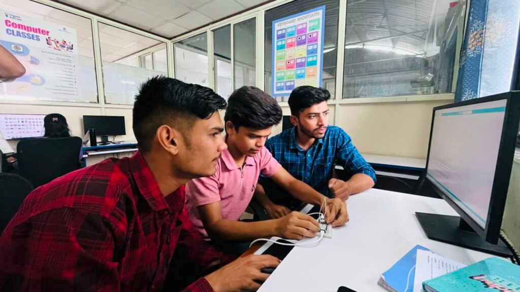
Wired communication was performed between two XIAO ESP32-C3 boards using UART (Universal Asynchronous Receiver-Transmitter) communication. The TX pin of the first board was connected to the RX pin of the second board, and the RX pin was connected to the TX pin. The GND pins of both boards were also connected together. One XIAO ESP32-C3 was used as the transmitter to send data, while the other was used as the receiver to receive and display the data through the Serial Monitor. This experiment demonstrated how two microcontrollers can exchange data directly through a wired serial connection.
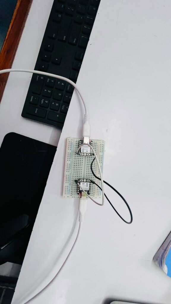
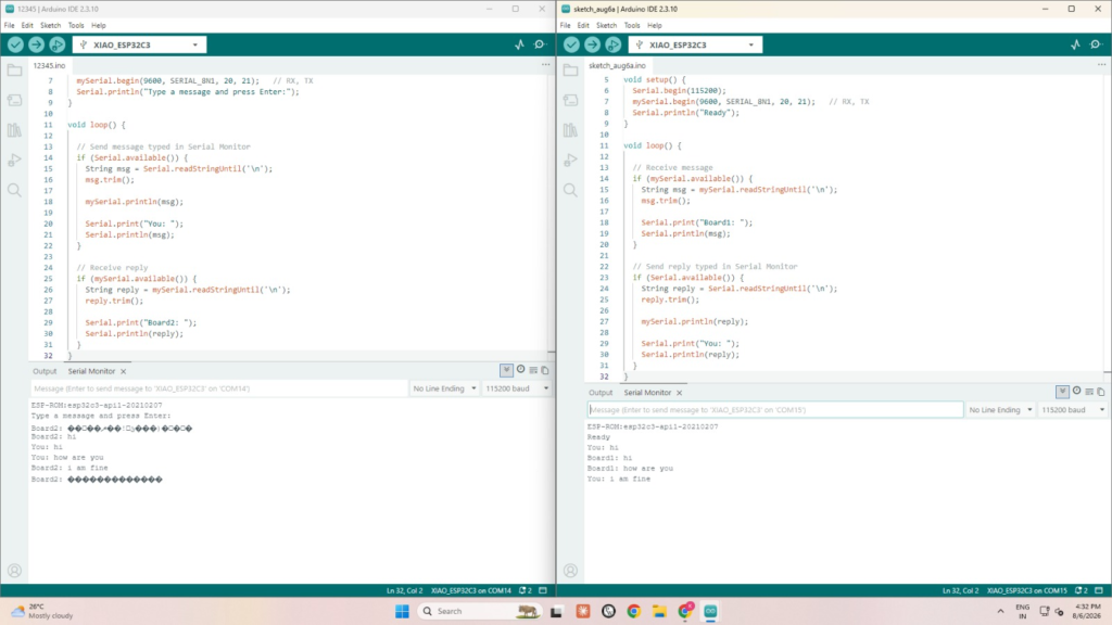
board 1
#include <HardwareSerial.h>

HardwareSerial mySerial(1);

void setup() {
  Serial.begin(115200);
  mySerial.begin(9600, SERIAL_8N1, 20, 21);   // RX, TX
  Serial.println("Type a message and press Enter:");
}

void loop() {

  // Send message typed in Serial Monitor
  if (Serial.available()) {
    String msg = Serial.readStringUntil('\n');
    msg.trim();

    mySerial.println(msg);

    Serial.print("You: ");
    Serial.println(msg);
  }

  // Receive reply
  if (mySerial.available()) {
    String reply = mySerial.readStringUntil('\n');
    reply.trim();

    Serial.print("Board2: ");
    Serial.println(reply);
  }
}
board 2
#include <HardwareSerial.h>

HardwareSerial mySerial(1);

void setup() {
  Serial.begin(115200);
  mySerial.begin(9600, SERIAL_8N1, 20, 21);   // RX, TX
  Serial.println("Ready");
}

void loop() {

  // Receive message
  if (mySerial.available()) {
    String msg = mySerial.readStringUntil('\n');
    msg.trim();

    Serial.print("Board1: ");
    Serial.println(msg);
  }

  // Send reply typed in Serial Monitor
  if (Serial.available()) {
    String reply = Serial.readStringUntil('\n');
    reply.trim();

    mySerial.println(reply);

    Serial.print("You: ");
    Serial.println(reply);
  }
}
Experience:
In this activity, we learned how to establish wired communication between two XIAO ESP32-C3 boards using UART. We connected the TX and RX pins correctly and used one board as a transmitter and the other as a receiver. We learned how data can be sent directly between two microcontrollers through wires. This activity improved our understanding of serial communication, wiring, and troubleshooting communication errors.
Individual Assignment
Bluetooth LED Control
In the individual assignment, we controlled an LED using an Arduino Uno and a Bluetooth module. The Bluetooth module was connected to the Arduino Uno to receive commands wirelessly from a mobile phone. We installed a Bluetooth control app on the mobile and used it to send 1** and 0 commands**. The Arduino received these commands and controlled the LED accordingly. This activity helped us understand Bluetooth communication, Arduino programming, and wireless control of electronic devices.
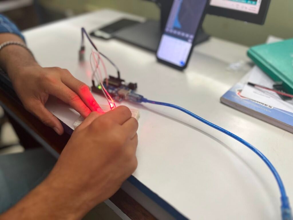
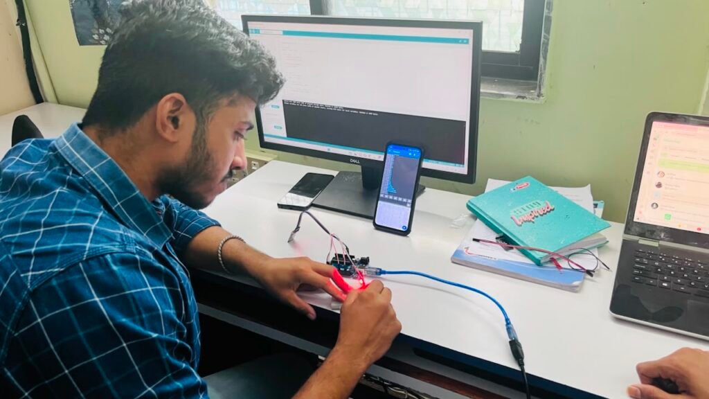
Commands from mobile app:
- Send
1→ LED ON - Send
0→ LED OFF
Bluetooth module connection (HC-06):
- VCC → 5V
- GND → GND
- TX → Arduino RX
- RX → Arduino TX
char data;
int ledPin = 8;

void setup() {
  pinMode(ledPin, OUTPUT);
  Serial.begin(9600);
}

void loop() {
  if (Serial.available()) {
    data = Serial.read();

    if (data == '1') {
      digitalWrite(ledPin, HIGH);
    }

    if (data == '0') {
      digitalWrite(ledPin, LOW);
    }
  }
}
Experience
In this activity, we learned how to control an LED wirelessly using an Arduino Uno and a Bluetooth module. We connected the Bluetooth module to the Arduino and used a mobile app to send 1 and 0 commands. It was interesting to see the LED respond to commands from the mobile phone. We also learned about Bluetooth communication, Arduino programming, and proper wiring. This activity gave us practical experience in controlling electronic devices wirelessly.
Individual Assignment –
MIT App Inventor and ESP32 LED Control
In my individual assignment, I developed a simple mobile application using MIT App Inventor to control an LED connected to an ESP32. The ESP32 was connected to the mobile phone through Wi-Fi, and the app was designed with buttons to turn the LED ON and OFF. When a button was pressed in the app, the ESP32 received the command and controlled the LED accordingly. This activity helped me understand MIT App Inventor, ESP32 Wi-Fi communication, app development, and IoT-based device control.
what is MIT app inventor
MIT App Inventor
MIT App Inventor is a web-based platform used to create mobile applications using a simple drag-and-drop interface and block-based programming. It allows users to develop Android applications without requiring advanced programming knowledge. In this assignment, MIT App Inventor was used to create a mobile application for controlling an LED connected to an ESP32. The app sends commands to the ESP32 through Wi-Fi, allowing the LED to be turned ON and OFF from the mobile phone.
steps a follow to create app on MIT app inventor
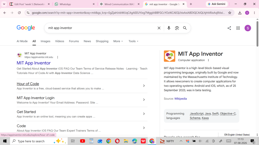
search MIT app inventor on google

open website and create account
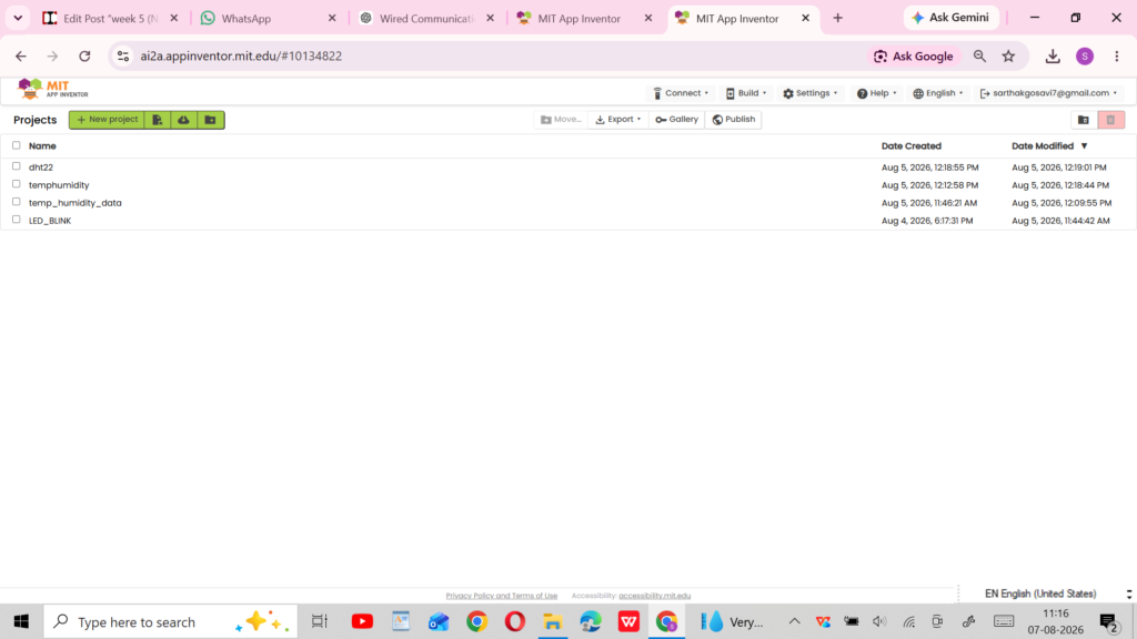
click on new project
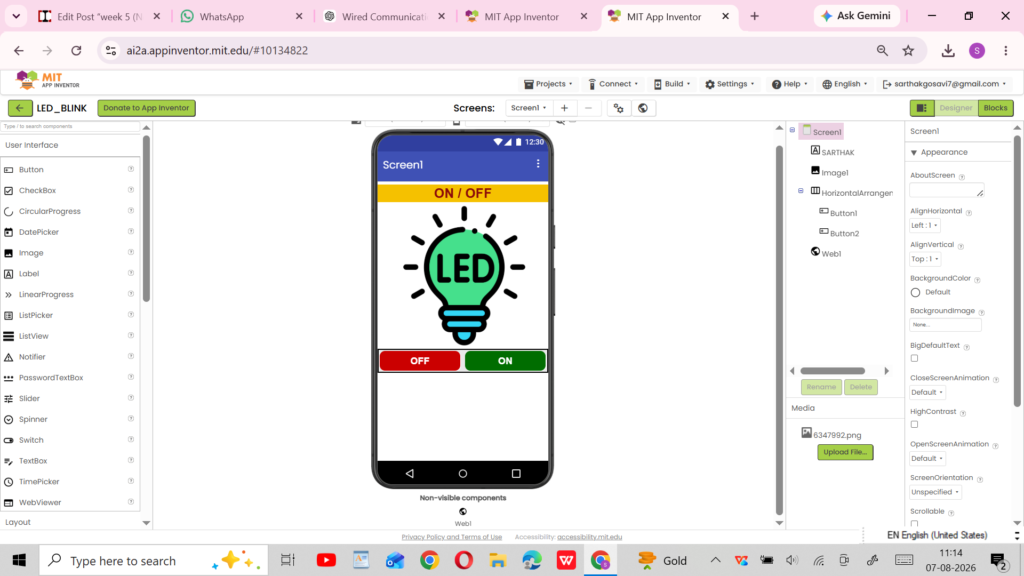
create a app interface as you need
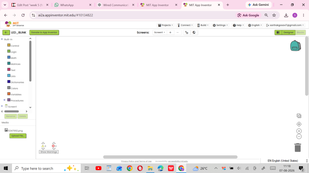
go to the blocks
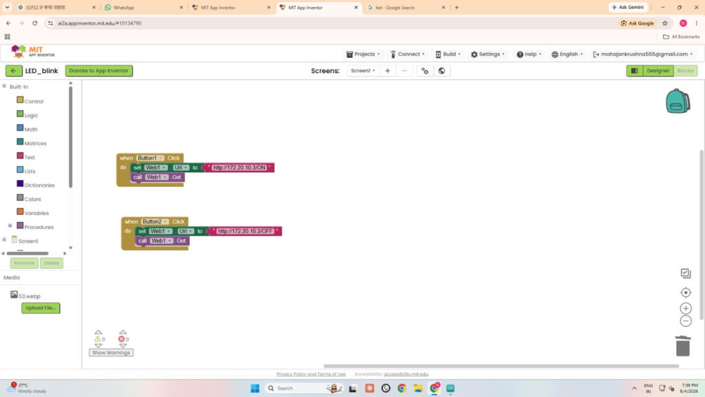
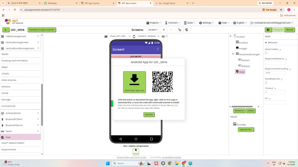
scan QR and download app on mobile
code
#include <WiFi.h>
#include <WebServer.h>

const char* ssid = "YOUR_WIFI_NAME";
const char* password = "YOUR_WIFI_PASSWORD";

WebServer server(80);

const int ledPin = 2;

void handleOn() {
  digitalWrite(ledPin, HIGH);
  server.send(200, "text/plain", "LED ON");
}

void handleOff() {
  digitalWrite(ledPin, LOW);
  server.send(200, "text/plain", "LED OFF");
}

void setup() {
  Serial.begin(115200);

  pinMode(ledPin, OUTPUT);
  digitalWrite(ledPin, LOW);

  WiFi.begin(ssid, password);

  while (WiFi.status() != WL_CONNECTED) {
    delay(500);
    Serial.print(".");
  }

  Serial.println();
  Serial.print("ESP32 IP Address: ");
  Serial.println(WiFi.localIP());

  server.on("/on", handleOn);
  server.on("/off", handleOff);

  server.begin();
}

void loop() {
  server.handleClient();
}
ESP32 Configuration
To connect the ESP32 with the MIT App Inventor application, the Wi-Fi network name and password were entered in the ESP32 program. The ESP32 was then connected to the same Wi-Fi network as the mobile phone. After successful connection, the ESP32 automatically displayed its IP address in the Serial Monitor. This IP address was used in the MIT App Inventor application to communicate with the ESP32 and control the LED. No IP address was required to be added manually to the ESP32 code.
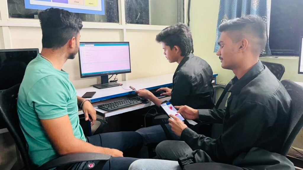
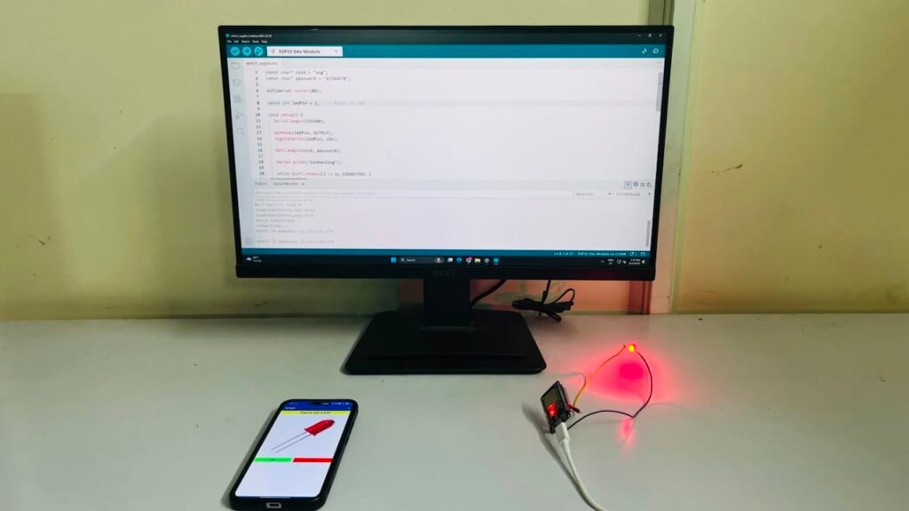
Experience
In this activity, I learned how to create a mobile application using MIT App Inventor and connect it with an ESP32 through Wi-Fi. I learned how to enter the Wi-Fi details, find the ESP32 IP address, and use it in the mobile application. I also learned how to create ON and OFF buttons using block programming to control an LED. This activity gave me practical experience in app development, Wi-Fi communication, ESP32 programming, and basic IoT control.
Individual Assignment –
Monitoring DHT22 Data on ThingSpeak
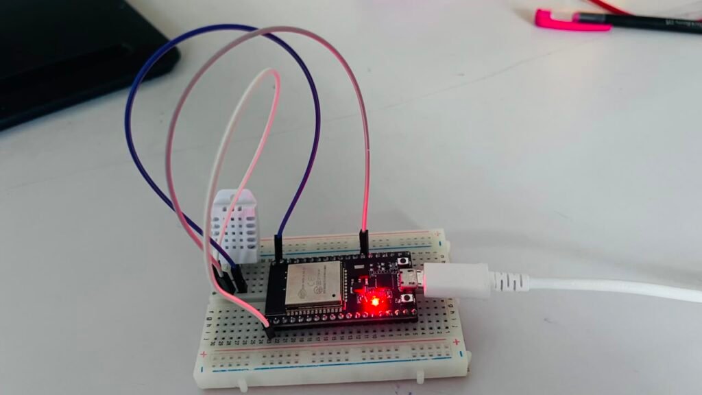
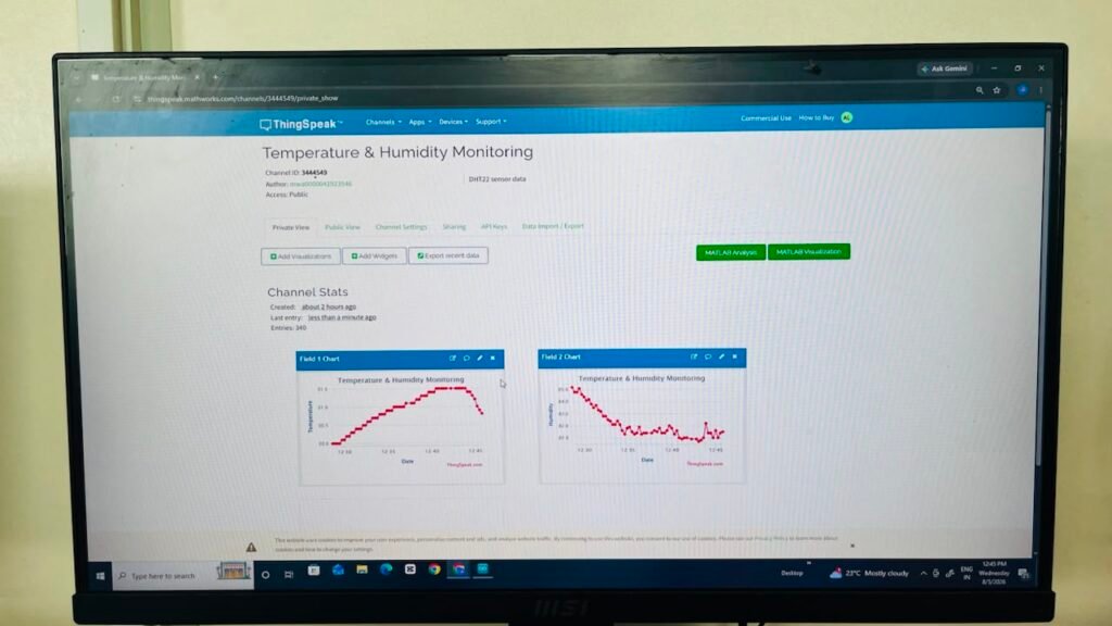
In my individual assignment, I used a DHT22 temperature and humidity sensor with an ESP32 to monitor environmental data on the ThingSpeak IoT platform. The DHT22 sensor was connected to the ESP32 and used to measure temperature and humidity. The ESP32 collected the sensor readings and sent the data to ThingSpeak through Wi-Fi. The temperature and humidity values were displayed on the ThingSpeak dashboard in the form of graphs. This activity helped me understand sensor interfacing, ESP32 Wi-Fi communication, cloud-based data monitoring, and IoT data visualization.
what is thinkspeak
ThingSpeak is an IoT cloud platform used to collect, store, analyze, and visualize data from sensors and microcontrollers such as ESP32 and Arduino. Devices can send sensor data to ThingSpeak through the internet, and the data can be displayed using graphs, charts, and other visualizations.
steps i follow to create channel on thinkspeak to monitor data
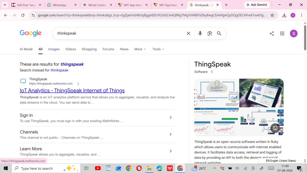
search thinkspeak on google
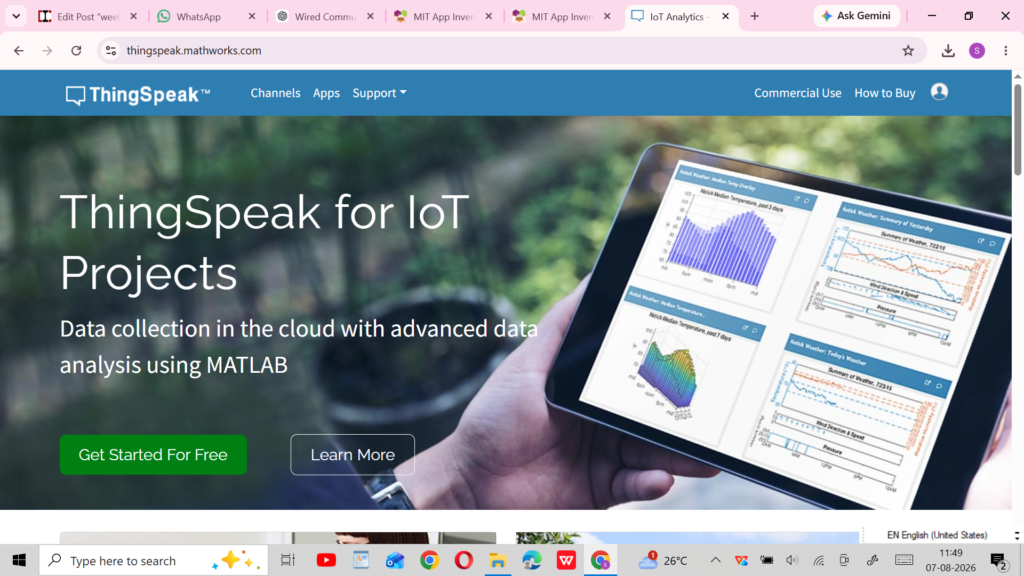
open web and login into thinkspeak with get started for free
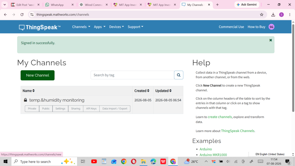
click on new channel and create a channel
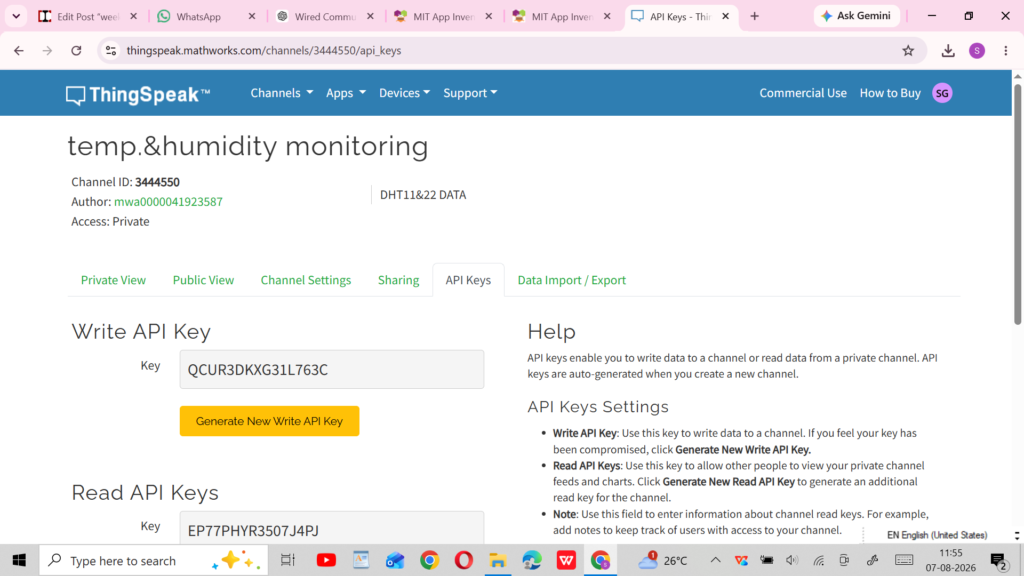
you need API kay for allow your ESP32 to send data to your specific ThingSpeak channel.
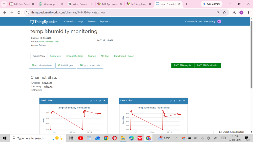
you also need channel id to identifies your channel
code
#include <WiFi.h>
#include <DHT.h>
#include <ThingSpeak.h>

// ===== Wi-Fi Details =====
const char* ssid = "YOUR_WIFI_NAME";
const char* password = "YOUR_WIFI_PASSWORD";

// ===== ThingSpeak Details =====
unsigned long channelID = YOUR_CHANNEL_ID;
const char* apiKey = "YOUR_WRITE_API_KEY";

// ===== DHT22 =====
#define DHTPIN 4
#define DHTTYPE DHT22

DHT dht(DHTPIN, DHTTYPE);

// ===== Wi-Fi =====
WiFiClient client;

void setup() {
  Serial.begin(115200);

  dht.begin();

  // Connect to Wi-Fi
  WiFi.begin(ssid, password);

  Serial.print("Connecting to Wi-Fi");

  while (WiFi.status() != WL_CONNECTED) {
    delay(500);
    Serial.print(".");
  }

  Serial.println();
  Serial.println("Wi-Fi Connected!");

  Serial.print("ESP32 IP Address: ");
  Serial.println(WiFi.localIP());

  // Start ThingSpeak
  ThingSpeak.begin(client);
}

void loop() {

  float temperature = dht.readTemperature();
  float humidity = dht.readHumidity();

  // Check sensor readings
  if (isnan(temperature) || isnan(humidity)) {
    Serial.println("Failed to read from DHT22 sensor!");
    delay(2000);
    return;
  }

  // Display readings
  Serial.print("Temperature: ");
  Serial.print(temperature);
  Serial.println(" °C");

  Serial.print("Humidity: ");
  Serial.print(humidity);
  Serial.println(" %");

  // Send data to ThingSpeak
  ThingSpeak.setField(1, temperature);
  ThingSpeak.setField(2, humidity);

  int response = ThingSpeak.writeFields(channelID, apiKey);

  if (response == 200) {
    Serial.println("Data sent successfully to ThingSpeak!");
  } else {
    Serial.print("Error sending data. Code: ");
    Serial.println(response);
  }

  Serial.println("----------------------");

  // ThingSpeak requires at least 15 seconds between updates
  delay(20000);
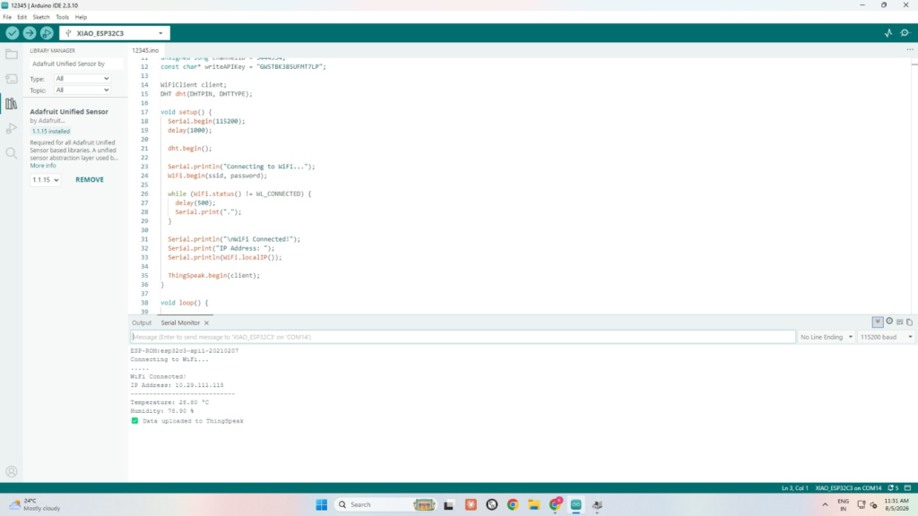
}
Experience
In this activity, I learned how to connect a DHT22 sensor with an ESP32 and monitor temperature and humidity data using ThingSpeak. I learned how to connect the sensor, program the ESP32, connect it to Wi-Fi, and send the sensor readings to the ThingSpeak cloud platform using a Channel ID and Write API Key. I also learned how to view the collected data through graphs. This activity gave me practical experience in sensor interfacing, IoT, cloud data monitoring, and wireless communication.
Week 5 – Overall Experience
In Week 5, I learned about Networking and Communication and gained practical experience with different communication methods. I worked with wired communication between two XIAO ESP32-C3 boards using UART and wireless communication using Bluetooth and Wi-Fi. I also created a mobile application using MIT App Inventor to control an LED connected to an ESP32. In another assignment, I used a DHT22 sensor with ESP32 to send temperature and humidity data to ThingSpeak for online monitoring. These activities helped me understand how microcontrollers communicate with each other, how mobile applications can control electronic devices, and how sensor data can be monitored through IoT cloud platforms. Overall, Week 5 improved my practical knowledge of UART, Bluetooth, Wi-Fi, IoT, MIT App Inventor, and ThingSpeak, while also improving my programming and troubleshooting skills.
end of week 5