INTRODUCTION
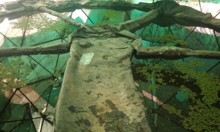
• Low tunnels are temporary, low-profile structures (usually 2 to 4 feet tall) that cover single single crop rows or beds. The frame is simple – often flexible PVC, or pushed directly into the soil. Tunnel film polyethylene (100-150 \mu). UV Stabilized: Prevents the plastic from shattering under sunlight. Infrared (IR) / Thermal: Traps long-wave heat radiation at night, keeping the interior significantly warmer. It Protects crops from adverse weather and Enables off- season cultivation.
OBJECTIVE
To create a controlled environment for plants by maintaining the temperature between 25- 27°C maintaining humidity above 60 to75% monitoring environmental conditions by manual data logging
METHODOLOGY
80% Shade-net is used for the outer covering: This is to restrict the amount of solar energy entering the polyhouse Cooling pads are used for temperature reduction and also for increasing humidity by evaporative cooling. exhaust fan is used to accelerate evaporative cooling Water circulation to keep pads wet
A digital humidity Temperature meter is used for temperature and humidity monitoring
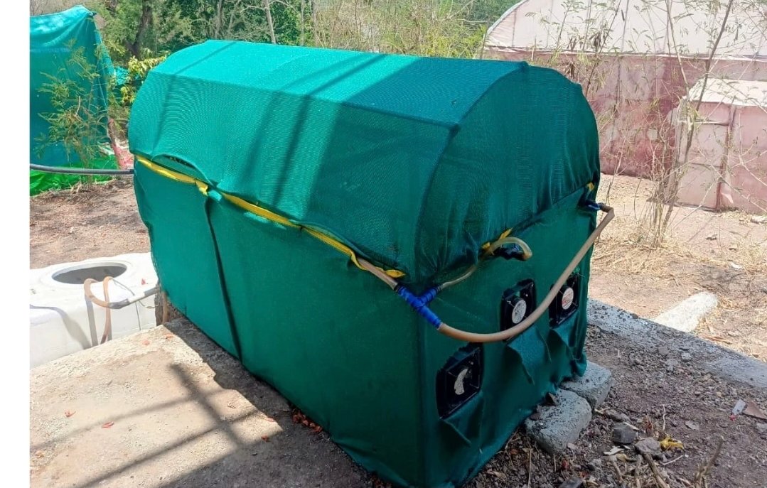
understanding previous project by nachiket that how a polyhouse works
Project planning
Originally the was to build the project with dimensions of 6 ft length, 4 ft height and width of 3 ft
However, after consulting with Arun Dixit Sir, the tunnel dimensions were set to a height of 2.5 feet and a length of 6 feet, featuring a rectangular flat head; a flat head was chosen because a dome-shaped tunnel would have resulted in higher aerodynamic drag.
MATERIAL SELECTION
Second week of july
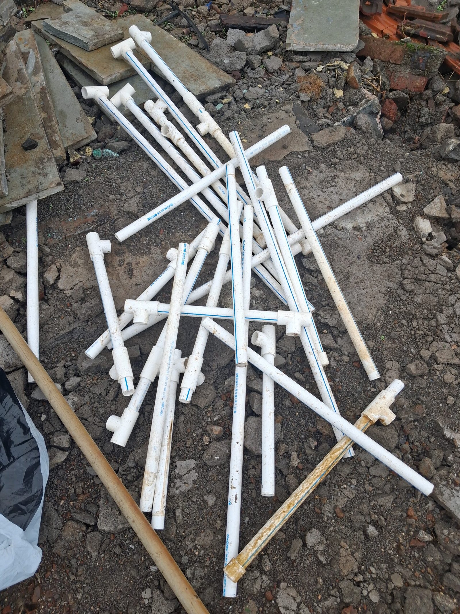
I have selected the pvc pipe material with elbow and T joint to construct the frame for tunnel, because of that frame will be lightweight and flexible compare to a metal frame
COOLING PAD INFORMATION
Area of the cooling pad will be decided by smaller rectangular in frame which will be opposite to fan section
Length of pad= 3 ft
width of pad =2.5 ft
Total area of pad required= 3×2.5 ft =7.5 square ft
COOLING FAN
Volume Calculation: l×b×h
6×3×2.5=45 cubic ft
Air Changes Per Hour (ACH): Greenhouses require 1 to 2 complete air changes per minute to control heat and humidity
Fan Sizing: volume ÷ minutes per exchange
For 1 air exchange per minute: 45 CFM (ideal for peak summer)
For 1 exchange every 2-3 minutes: 15 to 25 CFM
Temperature can goes very high here in pabal so I will use 50 CFM to 150 CFM fan for the tunnel
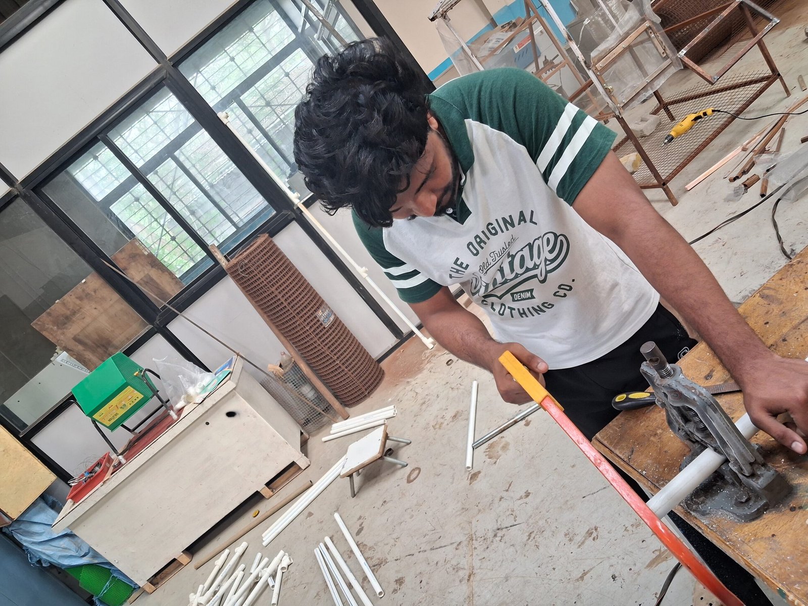
STARTED MATERIAL CUTTING FOR TUNNEL
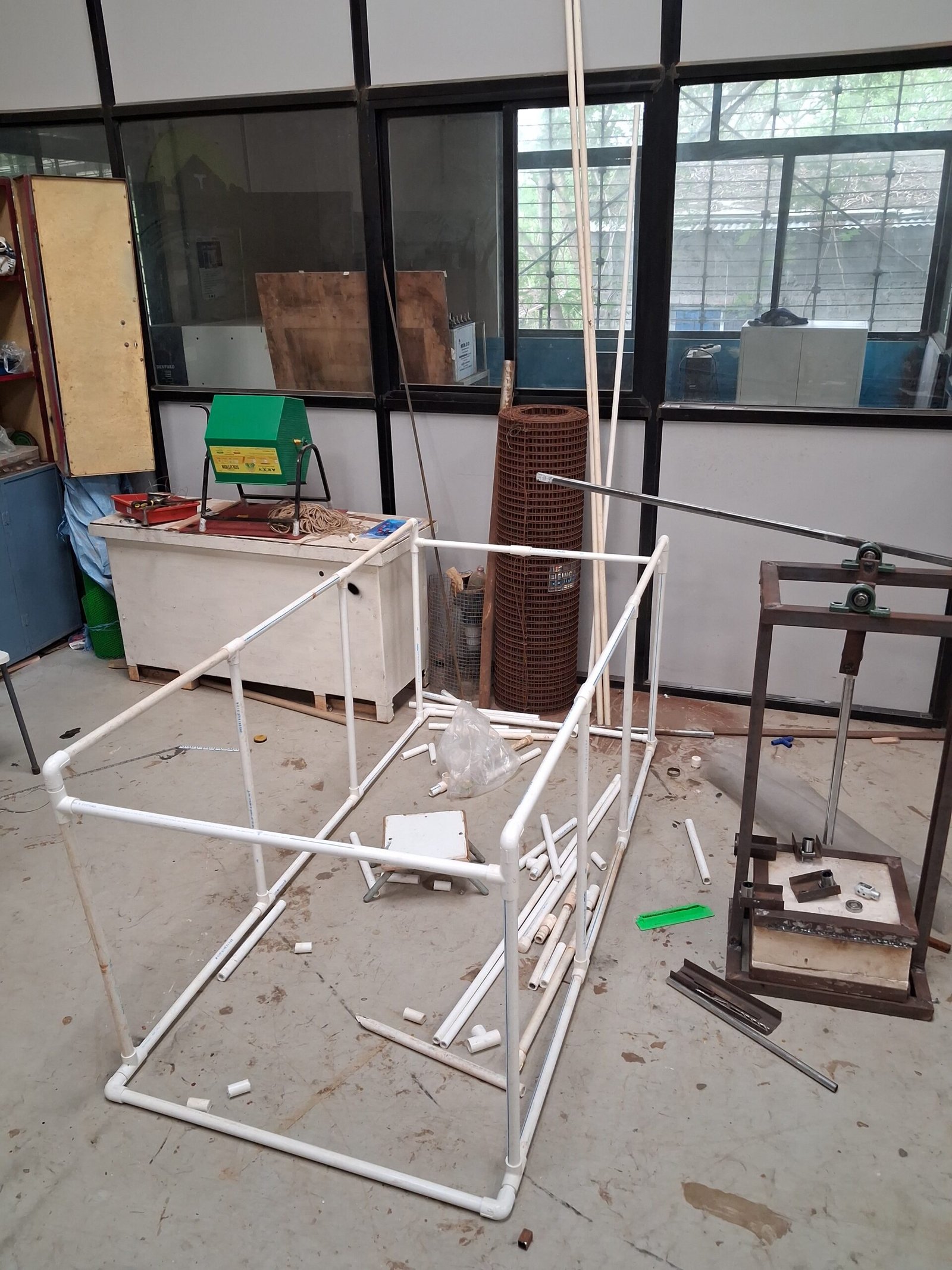
Carefully assembled final frame for the project
THIRD WEEK OF JULY
After assembling the frame, the most important task was to apply a 200-micrometer-thick film; this film would maintain distinct environments inside and outside the tunnel, retain internal humidity, and prevent rapid water evaporation.
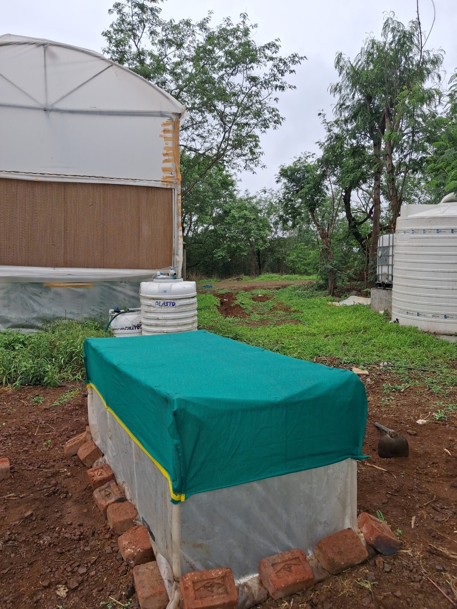
After installing the film, another key task was addressing the issue of direct, harsh sunlight hitting the plants. To protect them, it was necessary to install a shade net over the tunnel; I decided to use a net with 70–80% shading capacity, which would block out most of the sunlight. It wasn’t necessary to cover the entire tunnel—only the upper section exposed to direct sunlight needed protection—so I installed the shade net specifically there to prevent sun damage to the plants.
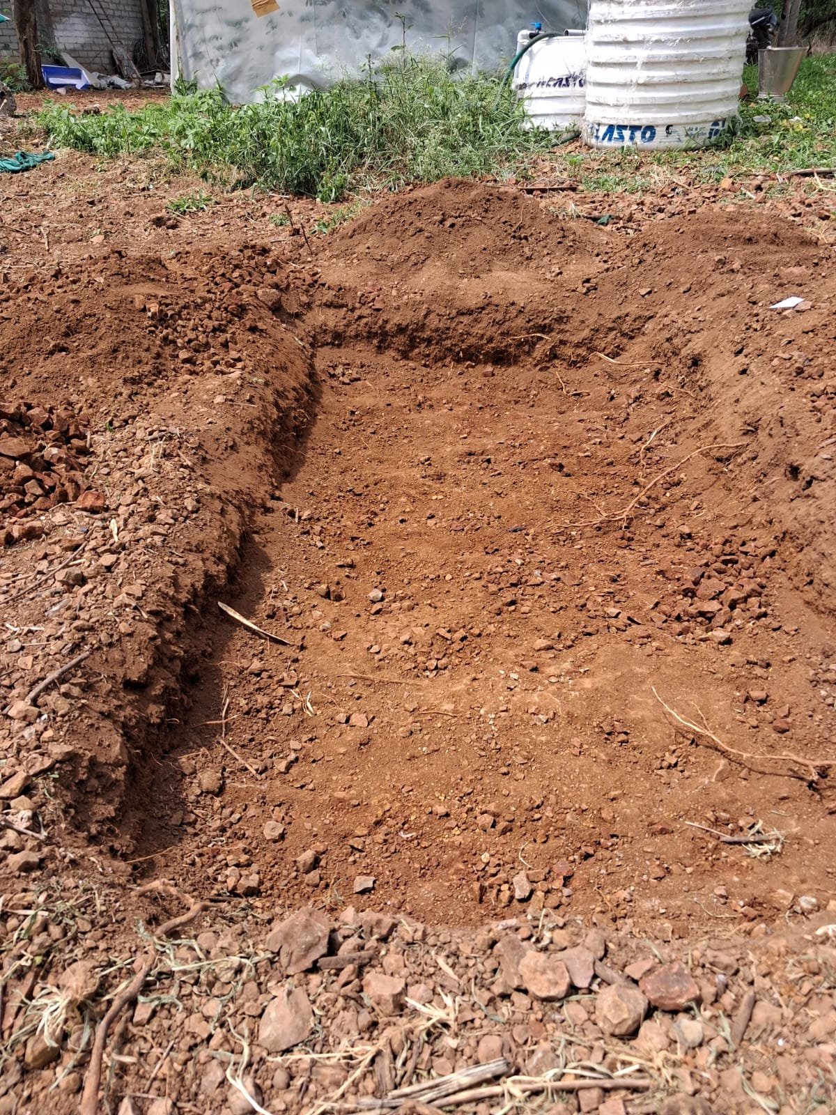
pit for root zone
- It is essential to dig a pit for the root zone; if we dig the pit without lining it with polyethylene, the irrigation water will simply percolate into the ground. Therefore, lining the pit with polyethylene helps conserve water and prevents it from seeping away.
SEEDBED PREPARATION
For seedbed preparation, the key step was to mix fertilizer into the soil—which had been dug out of the pit and then backfilled—to make it suitable for optimal plant growth; so, I mixed in organic fertilizer and tilled the soil using a hand cultivator.
PLANTATION
I chose Napier grass for planting, as it is excellent for animal feed; so, I found some Napier grass plants and cut their stems. Then, I planted the stems into the soil at an angle and finally watered them a little.
After the planting was done, the main task was figuring out how to secure the tunnel over the plants. To do this, I took metal rods, drove them into the ground along one side of the tunnel, and tied the tunnel frame to them to ensure stability. Finally, to fully secure the structure, I piled a bit of soil around the base and placed bricks against it; this ensured the interior was completely sealed and prevented humidity from leaking out.
Fourth week of july
DATA LOGGER INSTALLATION
- A data logger is a device that provides continuous information on temperature and humidity. So, I installed a data logger in this tunnel, and it kept providing me with data on the temperature and humidity.
- With this tunnel prototype, the main thing we need to observe is whether it protects the plants from damage caused by high temperatures. Since plants can get damaged in excessive heat, maintaining a temperature inside that is lower than the outside temperature during the day—especially around noon would be better for their growth.
WATER CHANNEL
During heavy rainfall, water can accumulate around the tunnel and seep inside, potentially damaging the plants; therefore, I constructed a water channel around the tunnel so that any excess rainwater would be diverted to the other side.
INCREASE IN TEMPERATURE
Using a data logger, I observed that during the day when there is sunlight the temperature inside the tunnel rises significantly, exceeding the outside ambient temperature by 7 to 8 degrees Celsius. I discussed this with Mr. Arun Dixit, who explained that warm, moist air rises because it is lighter than carbon dioxide; conversely, carbon dioxide is heavier and tends to settle at the bottom. Therefore, an exhaust vent was needed to expel this warm, moist air, and an intake was required to bring in fresh air (containing carbon dioxide), with the intake opening positioned near the bottom
DIMENSIONS AND LOCATION ON INTAKE ,EXAUST HOLES
For your small polyhouse with dimensions:
Length (L) = 6 ft = 1.829 m
Width (W) = 3.5 ft = 1.067 m
Height (H) = 3 ft = 0.914 m
1. Floor Area
A = L ×W
A = 1.829 ×1.067 = 1.95 m^2
2. Volume
V = L × W × H
V = 1.829 × 1.067 × 0.914 = 1.78 m^3
3. Total Ventilation Area
For natural ventilation, use 20% of the floor area.
A = 0.20 × 1.95 = 0.39 {m}^2
0.39{m}^2 = 3900{cm}^2
4. Divide into Intake and Exhaust
Intake (60%)
3900 × 0.60 = 2340{cm}^2
Two intake vents:
2340 ÷div 2 = 1170 {cm}^2 each
Practical size: 30 cm × 40 cm = 1200 cm² each.
Exhaust (40%)
3900 ×0.40 = 1560 {cm}^2
One roof vent: 40 cm × 40 cm = 1600 cm².
Final Vent Design
1. 2 Intake vents: 30 cm × 20 cm each, positioned 10–15 cm above the ground on opposite long sides.
2. 1 Exhaust vent: 40 cm × 30 cm, at the highest point of the roof.
This vent arrangement is appropriate for 6 ft × 3.5 ft × 3 ft polyhouse and should provide effective natural ventilation while maintaining good airflow.
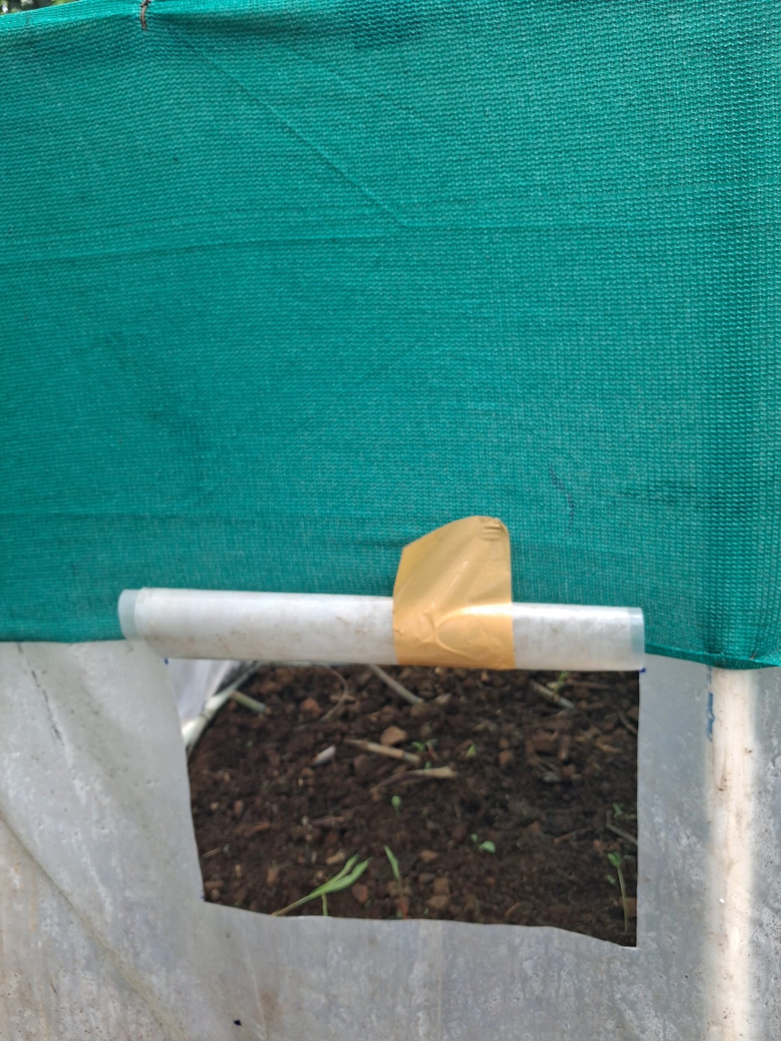
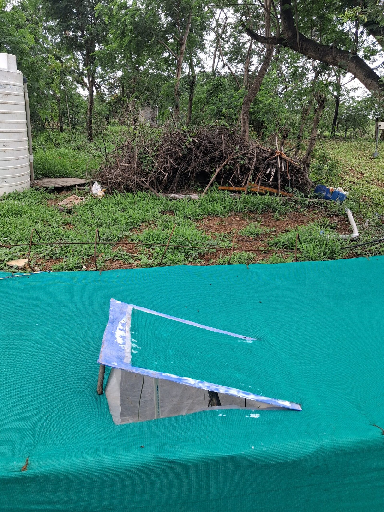
- After installing the vents, I noticed a drop in temperature.
- The internal temperature was higher before the vents were created, and it decreased after they were built.
This temperature was before the installation of intake and Exhaust holes
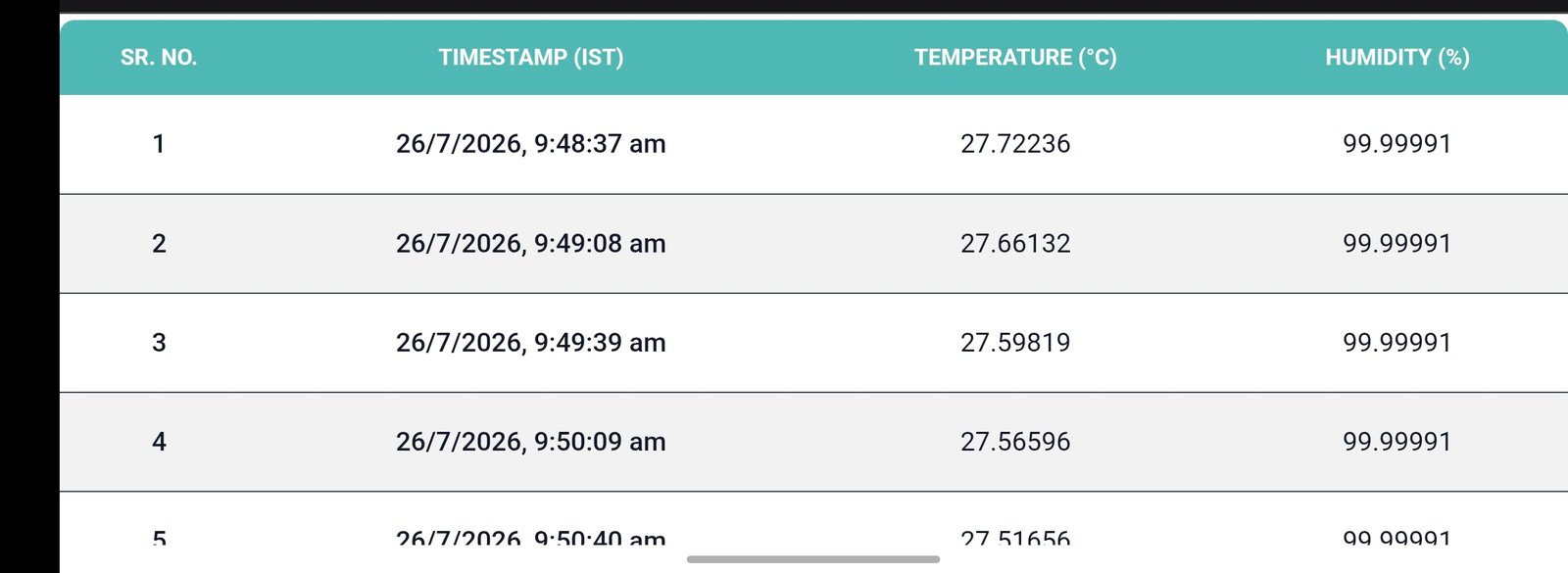
And this temperature reading i got after the installation of vents
The Tunnel Farming project was carried out to study plant growth, temperature management, humidity, and water utilization under a low-cost protected cultivation structure.
A significant result of the project was the growth of Napier grass. Normally, Napier grass can grow around 1.5–2 feet in one month, whereas the plants inside our tunnel achieved almost 3 feet of growth in approximately one month. This indicates that the protected environment provided favourable conditions for plant growth.
Water requirement was also found to be very low. The plants were watered on 20th, and no additional watering was required during the observation period. The polythene-lined pit below the growing area helped retain moisture and reduced water loss, demonstrating the potential for water conservation.
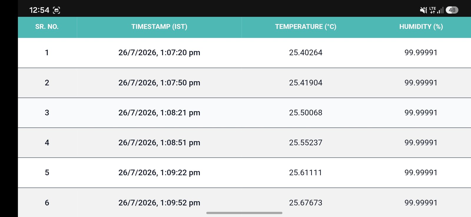
The temperature readings collected from 22–27 July 2026 showed an average temperature of approximately 24.71°C, with temperatures falling to around 22–23°C during cooler periods. This indicates that the tunnel was capable of moderating its internal temperature. However, since outdoor temperature readings were not recorded simultaneously, the exact temperature reduction could not be calculated.
Humidity readings remained close to 100%, so effective humidity control could not be demonstrated. Better ventilation and improved humidity monitoring would be required in future trials.
Overall, the project successfully demonstrated significant plant growth, low water requirement, and temperature moderation. The results show that a simple and low-cost tunnel farming structure can have good potential for efficient and protected crop cultivation.
With these observations and results, the Tunnel Farming project is successfully concluded.
DESIGNING AN ADVANCED TUNNEL FOR LEMONGRASS CULTIVATION
As a continuation of my earlier Tunnel Farming Project, I am now working on developing a larger and more versatile tunnel farming system. The objective of this new phase is to study plant growth under protected conditions and compare it with growth in an open field.
PROJECT DISCUSSION & PLANNING
I discussed the next phase of the project with Arun Dixit Sir, where we decided to construct two larger tunnels and grow lemongrass inside them. Along with the two tunnels, lemongrass will also be grown in an open-field plot. The growth of the plants will be monitored and compared through parameters such as plant growth, grading and other observations.
Initially, a tunnel size of 6 m × 1 m × 1 m was considered. However, after discussing the project with Bhanudas Sir and studying the available field, it was decided to increase the tunnel length to 8 m so that the available land can be utilized more effectively and the structure can also be useful for future experiments.
FINAL TUNNEL DESIGN
The proposed tunnel will have the following dimensions:
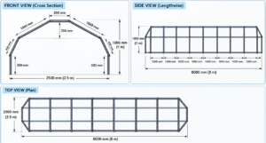
- Length: 8 m
- Width: 2.5 m
- Height: 1 m
- Number of tunnels: 2
The available field is approximately 19 m², with a perimeter of around 50 m and a width of approximately 10–12 m. The larger tunnel size will make better use of the available space and provide greater scope for future agricultural experiments.
MATERIAL SELECTION
Initially, PVC pipes or bamboo were considered for constructing the tunnel frame. However, for a larger structure, PVC could be relatively expensive, and forming a strong arched structure can require additional time and effort.
Therefore, after discussion with Bhanudas Sir, TMT rebar was selected for the main frame. TMT rebar can be bent into the required arch shape and welded to create a strong and stable structure. This makes it suitable for developing a larger tunnel while keeping the construction practical and economical.
NEXT STEPS
The next stage will be to construct the two TMT-rebar tunnels, prepare the growing area and plant lemongrass. Growth observations will then be recorded for both tunnels and compared with the open-field crop.
EXPECTED OUTCOME
This experiment will help us understand how a larger tunnel structure affects plant growth and will also provide a practical design that can be modified and reused for future tunnel farming experiments at Vigyan Ashram.
08/09/26 – 13/09/26
Weekly Progress – Advanced PVC Tunnel Farming Structure
This week, our main focus was on the design, material selection, and fabrication
of an advanced tunnel farming structure. We started with an initial TMT
rebar-based design and then reconsidered the material and structural design based on
practical fabrication requirements and field conditions.
1. Initial TMT Rebar Design
Initially, we planned to construct the tunnel structure using
TMT rebar. The objective was to develop an arc-shaped frame that
could provide sufficient space for crop growth while maintaining structural stability.
This gave us a practical reference for understanding the required shape, dimensions,
and structural arrangement of the tunnel.
2. Why We Shifted from TMT to PVC Pipe
After developing the initial TMT design, we reconsidered the material because the
tunnel structure will be installed and used inside the agricultural field.
In field conditions, the structure will be continuously exposed to
moisture, water, and soil contact.
Since TMT is a ferrous material, continuous exposure to moisture can lead to
corrosion. Over a longer period, corrosion may reduce the strength
and durability of the frame and affect its ability to sustain in field conditions.
Therefore, we decided that PVC pipe would be a more suitable material
for this application. PVC is not affected by corrosion in the same way as TMT and is
better suited for a structure that will remain exposed to moisture for long periods.
It is also lightweight, flexible, easy to handle, and easier to assemble into the
required tunnel shape.
3. Reconsideration of the Tunnel Shape
During the design process, we initially considered making the top of the triangular
structure completely sharp or pointed. However, while converting the
design into a practical PVC structure, we found that this shape could not be easily
fabricated using the available market fittings.
The main difficulty was the availability of suitable elbow joints.
The specific type of elbow joint required to create a completely sharp triangular
peak was not readily available in the market. Fabricating or modifying
such a joint would make the structure more complicated and less practical.
Therefore, we reconsidered the design and changed the sharp triangular peak into a
flat-top hut-shaped design. This allowed us to use commonly available
PVC joints and construct the frame more easily while maintaining the required tunnel
dimensions and structural stability.
After considering the availability of fittings, ease of fabrication, structural
requirements, and practicality, the flat hut-shaped PVC design was finally
selected for the tunnel.
4. Selection of 32 mm PVC Pipe
For the final PVC tunnel, we selected a 32 mm diameter PVC pipe
instead of a 25 mm pipe. The main reason for selecting the larger diameter was the
long length of our tunnel structure.
Since our tunnel is relatively long, we required a pipe that could provide better
rigidity and stability and would not bend easily during installation or under its
own span. A 25 mm PVC pipe could bend more easily over the longer structure, whereas
the 32 mm pipe provides better stiffness and stability.
Another important consideration was the cost difference between the two sizes.
The price difference between 25 mm and 32 mm PVC pipes was not very high.
Therefore, we preferred the 32 mm pipe to achieve better stability and strength for
the overall structure.
5. Final Tunnel Dimensions
After finalizing the material and structure, the dimensions of the advanced tunnel
were finalized as follows:
| Parameter | Specification |
|---|---|
| Tunnel Length | 20 feet |
| Tunnel Width | 5 feet |
| Tunnel Height | 4 feet |
| PVC Pipe Diameter | 32 mm |
| Number of Tunnels | 2 |
| Tunnel Shape | Flat-top Hut Type |
6. Triangular Frame Design
The tunnel consists of repeated triangular frame sections arranged along its length.
The dimensions were planned to maintain a uniform and symmetrical structure throughout
the tunnel.
- Base width of triangular section: 5 feet
- Vertical pipe height: 2.6 feet
- Left lateral rise: 2.5 feet
- Right lateral rise: 2.5 feet
- Spacing between consecutive triangular frames: 1 metre
The equal lateral rises on both sides help maintain symmetry in the structure.
The triangular frames are positioned at a regular spacing of
1 metre along the tunnel length to provide proper support to the
covering material and maintain the overall shape.
7. Fabrication of the First Tunnel
After finalizing the design and dimensions, we started the fabrication work using
32 mm PVC pipes. The pipes were cut according to the calculated
dimensions and assembled using the required PVC joints.
The base frame was assembled first, followed by the vertical supports and the
sloping sections of the triangular frames. The different sections were connected
using suitable PVC joints to achieve the required flat-top hut-shaped tunnel profile.
By Sunday, we successfully completed the fabrication of the first tunnel.
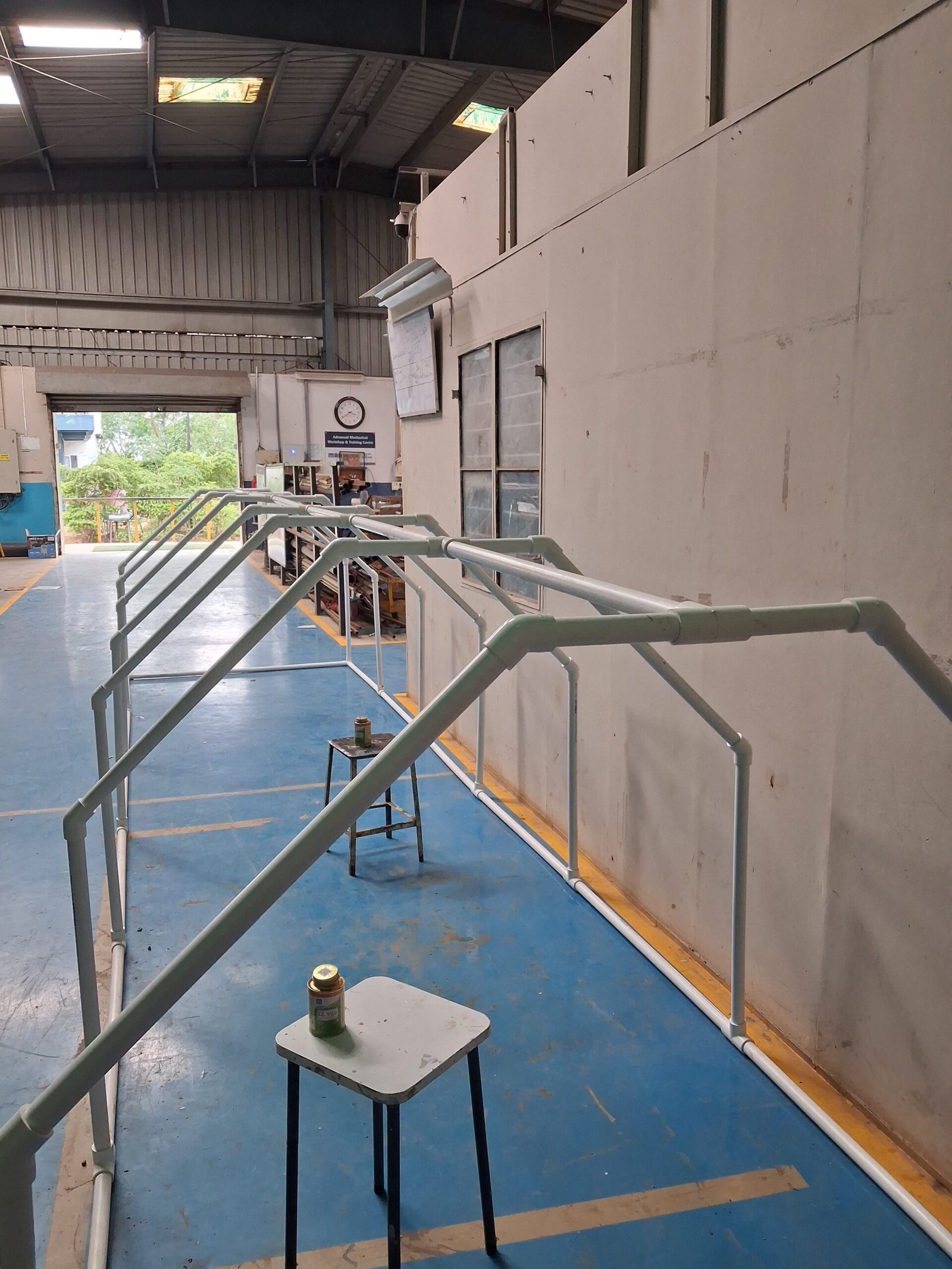
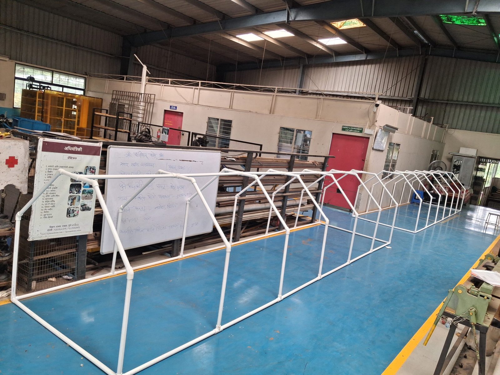
The photographs show the completed PVC frame and its triangular support arrangement.
8. Construction of the Second Tunnel
Our project involves the construction of two similar advanced PVC tunnels.
The first tunnel has been successfully completed this week, and the fabrication of the
second tunnel is planned for the next working day.
The same finalized dimensions and structural arrangement will be followed for the
second tunnel.
9. Next Work – Polyethylene Film and Shade Net
After completing both PVC tunnel frames, the next stage will be to cover the
structures with polyethylene film. The film will be properly
positioned and secured to the PVC frame.
After the polyethylene film is installed, the next step will be the installation
of the shade net. The shade net will be fixed properly over the
required portion of the tunnel to provide the required shading and help reduce
direct solar radiation inside the tunnel.
- Complete fabrication of the second PVC tunnel.
- Install polyethylene film on both tunnel structures.
- Secure the polyethylene film properly to the PVC frame.
- Install the required shade net.
- Secure the shade net properly using suitable ties and fasteners.
Weekly Progress
This week, we successfully progressed from the initial TMT rebar concept
to a practical 32 mm PVC-based tunnel design. During the design process,
we also reconsidered the sharp triangular top because the required elbow joints were
not practically available in the market. As a result, we finalized a
flat-top hut-shaped design that is easier to fabricate using
available PVC fittings.
We finalized the dimensions and successfully completed the fabrication of the
first 20 ft × 5 ft × 4 ft tunnel. The second tunnel will be
fabricated next, after which both structures will be covered with polyethylene film
and shade net.
Weekly Progress – Tunnel Farming Project
|
-: 20 September 2026
Project Progress
During the previous week, the frame construction of the first PVC tunnel
was completed. Continuing the work this week, the frame of the
second tunnel was also successfully completed.
With this, the structural framework of both tunnels is now ready.
The project has now moved towards the next stage, which includes the
installation of the polyethylene sheet, shade net and ventilation
arrangement. However, the covering work is currently on hold due to the
unavailability of the required polyethylene sheet.
Both PVC tunnel frames have been completed. The remaining work is mainly
related to tunnel covering and ventilation.
Polyethylene Sheet Requirement
Approximately 800 sq. ft. of polyethylene sheet is
required to complete the covering of the tunnels. The sheet could not
be arranged during this week, which has temporarily delayed the next
stage of construction.
Banudas Sir has taken responsibility for arranging the required
polyethylene sheet and is expected to bring it by Monday. Once the
material is available, the remaining installation work is expected to
take approximately 1–2 days.
Shade Net and Polyethylene Layer Arrangement
An important design consideration this week was the arrangement of the
polyethylene sheet and shade net. Ranjit Sir suggested maintaining a
small gap between the two layers.
The shade net is dark in colour and therefore absorbs solar radiation,
causing it to become warm. If the shade net remains in direct contact
with the polyethylene sheet, heat can be transferred from the shade net
to the polyethylene layer.
To reduce this direct heat transfer, the final arrangement will keep the
polyethylene sheet on the inner side of the tunnel frame and the
shade net on the outer side. This will create a small air gap
between the two layers.
The air gap will provide thermal separation between the shade net and
polyethylene sheet and is expected to reduce direct heat transfer into
the tunnel. This arrangement is particularly important because the
primary objective of the shade net is to reduce excessive solar heat
reaching the tunnel.
Ventilation System
Along with the covering, proper ventilation will be provided to manage
the internal air movement and reduce heat accumulation.
The planned ventilation arrangement consists of air inlets at the lower
portion of the tunnel and air outlets at the upper portion.
- Lower air inlets:
These openings will allow relatively cooler outside air to enter
the tunnel. - Upper air outlets:
These openings will allow warm air to escape from the tunnel.
This arrangement is based on the natural movement of warm air. As air
inside the tunnel becomes warmer, it tends to rise and can escape
through the upper openings. Fresh air can then enter through the lower
openings, helping to establish continuous natural air circulation.
Current Status
The structural work of both tunnels is now complete. The project is
temporarily paused because the polyethylene sheet and shade net required
for the covering stage are yet to be arranged.
Once the polyethylene sheet is available, the installation will be
started immediately. The covering, shade-net arrangement and ventilation
openings are expected to be completed within approximately
1–2 days.
Plan for the Coming Week
- Arrange approximately 800 sq. ft. of polyethylene sheet.
- Install the polyethylene sheet on the inner side of the tunnel frame.
- Install the shade net on the outer side of the frame.
- Maintain a suitable air gap between the two layers.
- Provide lower air-inlet openings.
- Provide upper air-outlet openings.
- Complete the covering and ventilation work of both tunnels.
- Prepare the tunnels for the next stage of testing
Tunnel Farming: Polyethylene Covering, Ventilation Design, Shade Net : 21 September – 4 October 2026
1. Introduction
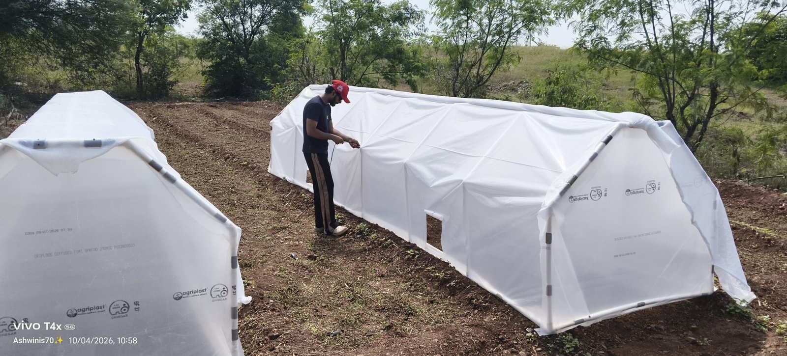
During the last two weeks, the tunnel farming project progressed from the completion of the two PVC tunnel frames to the installation of polyethylene sheets, ventilation openings, shade nets and environmental monitoring equipment.
By 20 September, the basic frames of both tunnels had been completed. During the following two weeks, the main focus was on making the structures functional and preparing them for field testing. The major activities included polyethylene sheet installation, development of custom clamps, ventilation design, installation of a 50% white shade net and installation of data loggers.
2. Week 1: 21–27 September – Planning and Preparation
During the first week, the main work involved planning the covering and ventilation arrangements for both completed PVC tunnel structures. Different methods for fixing the polyethylene sheet were considered, along with the required ventilation opening area and the type of shade net suitable for the tunnels.
The ventilation design was discussed with Arun Dixit Sir before the openings were made. The design considered the tunnel dimensions, natural ventilation requirements and the need to maintain sufficient airflow while avoiding unnecessarily large openings.
3. Week 2: 28 September – 4 October – Tunnel Completion and Monitoring
3.1 Polyethylene Sheet Installation
The first major activity was covering both PVC tunnel frames with polyethylene sheets. The sheet needed to be firmly secured to the frame while avoiding damage to the plastic material.
Binding wire and ordinary zip ties were not preferred for directly fixing the polyethylene sheet because concentrated pressure and sharp contact points could increase the possibility of tearing the sheet.
To solve this problem, custom clamps were designed and fabricated using PVC pipe pieces. These clamps provided a wider and smoother contact area for holding the polyethylene sheet against the PVC frame. They also made the sheet easier to install and adjust without creating unnecessary holes or concentrated stress points.
Using these custom-made clamps, polyethylene sheets were installed over both tunnel structures.
3.2 Basis for Ventilation Area Selection
After installing the polyethylene covering, ventilation openings were provided to allow fresh air to enter the tunnel and warm air to escape.
For the initial design, published protected-cultivation guidance was considered. A review of protected cultivation practices in India reports that for naturally ventilated greenhouses, the minimum top ventilation can be approximately 10% of the greenhouse floor area, while side ventilation is provided separately according to the greenhouse design and climatic requirement.
This 10% value was therefore used as a reference point while planning the ventilation of the experimental tunnel. It should be understood as a design reference rather than a universal requirement for every tunnel or greenhouse.
3.3 Calculation of the Reference Ventilation Area
The dimensions of each tunnel were:
- Length = 20 ft
- Width = 5 ft
- Height = 4 ft
First, the floor area was calculated:
Floor Area = Length × Width
Floor Area = 20 × 5 = 100 sq ft
Taking 10% of the floor area as the reference ventilation area:
Reference Ventilation Area = 100 × 10%
Reference Ventilation Area = 10 sq ft
Therefore, 10 sq ft was considered as the reference value for the ventilation opening area.
3.4 Selection of 8 sq ft Opening Area
Although 10 sq ft was obtained as the reference value, we decided to initially provide a slightly smaller total opening area of 8 sq ft per tunnel.
This was done because the project is an experimental tunnel-farming setup, and the ventilation performance will be evaluated using actual field temperature data. Starting with a slightly smaller opening area also allows the ventilation area to be increased later if the monitoring results show that additional cooling is required.
The selected ventilation arrangement consisted of:
- 4 inlet openings × 1 sq ft = 4 sq ft
- 4 outlet openings × 1 sq ft = 4 sq ft
Therefore:
Total Opening Area = 4 + 4 = 8 sq ft
Compared with the 100 sq ft floor area:
Opening Area Percentage = (8 ÷ 100) × 100 = 8%
Thus, the initial tunnel design uses a total nominal opening area equal to approximately 8% of the floor area, compared with the 10% reference value used during the design process.
3.5 40 ACH Ventilation Calculation
Along with the floor-area approach, a target of 40 Air Changes per Hour (ACH) was considered for the tunnel ventilation design.
Tunnel volume:
Volume = Length × Width × Height
Volume = 20 × 5 × 4 = 400 cubic ft
For 40 ACH:
Required Airflow = 400 × 40 = 16,000 cubic ft/hour
Converting this into cubic feet per minute:
16,000 ÷ 60 ≈ 267 CFM
Therefore, the theoretical airflow corresponding to 40 ACH is approximately 267 CFM per tunnel.
The 40 ACH value is being used as a design target. Since the tunnels use natural ventilation openings rather than a dedicated exhaust fan system, the actual air exchange will depend on wind speed, temperature difference, opening geometry and resistance from the polyethylene and shade-net materials. Therefore, the actual ventilation performance will be evaluated through field observations and temperature data.
3.6 Inlet and Outlet Arrangement
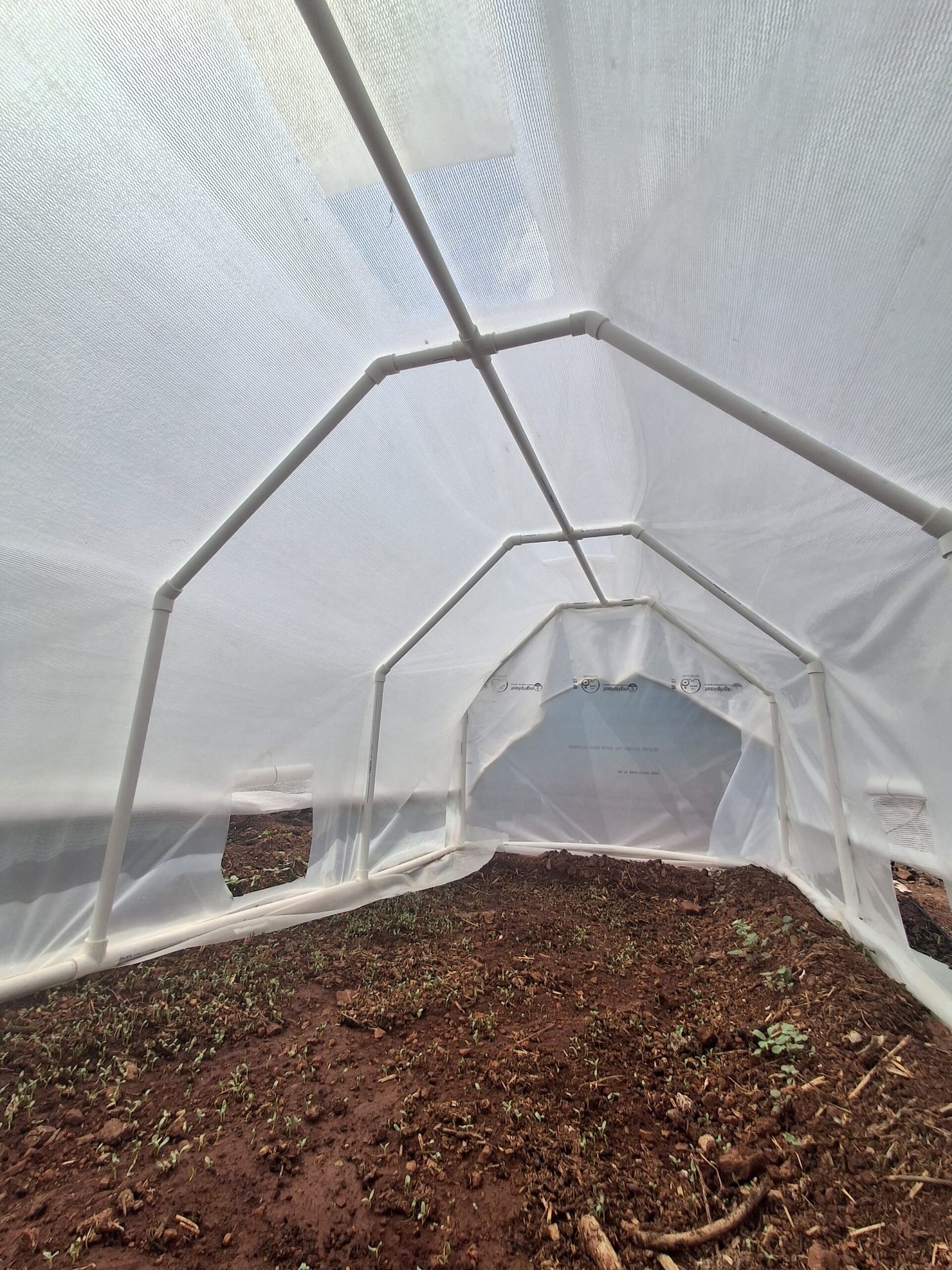
Four inlet openings and four outlet openings were provided in each tunnel.
The inlet openings allow relatively cooler outdoor air to enter the tunnel, while the outlet openings provide a path for warmer air to leave. The openings were distributed along the tunnel to encourage air movement through the structure rather than concentrating ventilation at a single location.
The selected opening area can be increased in the future if the recorded temperature data indicates that additional ventilation is required.
3.7 Installation of 50% White Shade Net
After completing the ventilation openings, a shade net was installed over the polyethylene covering of both tunnels.
Higher shading percentages such as 80% and 90% were available in the market. However, these were not selected because excessive shading could reduce the amount of sunlight reaching the plants.
Therefore, a 50% shade net was selected as the initial option. This provides a balance between reducing excessive solar radiation and maintaining sufficient light availability for crop growth.
A white-coloured shade net was selected because white surfaces generally reflect a greater proportion of incoming solar radiation and absorb less solar energy than darker surfaces. This can help reduce heating of the shading material and potentially reduce heat transfer to the tunnel.
The actual effect of the white shade net will be evaluated using the temperature data collected from the tunnels.
3.8 Shifting the Tunnels to the Field
After completing the polyethylene covering, ventilation openings and shade-net installation, both tunnel structures were shifted to the field.
This was an important step because the tunnels needed to be tested under actual outdoor weather conditions. The next stage was therefore focused on monitoring the environmental conditions inside the tunnels and comparing them with the outdoor conditions.
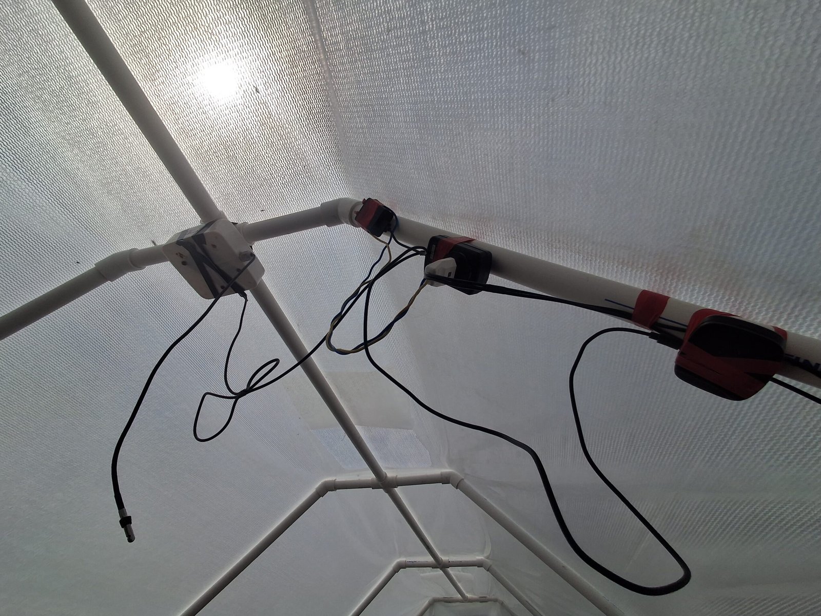
3.9 Installation of Data Loggers
To continuously monitor the tunnel environment, one data logger was installed inside Tunnel 1 and another data logger was installed inside Tunnel 2.
The nearby Outdoor Weather Station 1 was used as the reference location for the monitoring setup. Electricity was taken from the weather-station area, and a Wi-Fi dongle was installed in the tunnel area to provide connectivity for the data loggers.
With this setup, continuous readings can be collected from both tunnels and compared with the outdoor weather conditions.
4. Current Status
- Both PVC tunnel structures completed.
- Polyethylene sheets installed over both tunnels.
- Custom PVC clamps developed to secure the polyethylene sheet.
- Four inlet and four outlet openings provided in each tunnel.
- Initial total opening area selected as 8 sq ft per tunnel.
- 40 ACH considered as the initial ventilation design target.
- 50% white shade net installed.
- Both tunnels shifted to the field.
- One data logger installed inside each tunnel.
- Wi-Fi and power arrangements established for continuous monitoring.
5. Next Steps
The next phase will focus on collecting and analysing the environmental data from both tunnel data loggers and the nearby outdoor weather station.
Temperature will be the primary parameter for evaluating the performance of the tunnel system. Humidity will also be recorded as an additional environmental parameter.
The recorded data will help determine whether the 8 sq ft ventilation arrangement and 50% white shade net are providing sufficient temperature control. If higher cooling is required, the ventilation opening area can be increased based on the field observations.
6. Conclusion
During the two-week period from 21 September to 4 October, both tunnel structures progressed from completed PVC frames to fully covered and field-installed experimental structures.
Polyethylene sheets were secured using custom-designed PVC clamps to reduce the risk of tearing. Ventilation was planned using a 10% floor-area reference, resulting in a reference value of 10 sq ft for the 100 sq ft tunnel floor. For the initial experimental setup, a slightly smaller total opening area of 8 sq ft was selected, consisting of four 1 sq ft inlet openings and four 1 sq ft outlet openings.
A theoretical ventilation target of 40 ACH was also considered, corresponding to approximately 267 CFM for the 400 cubic ft tunnel volume. A 50% white shade net was installed to reduce excessive solar radiation while maintaining adequate light for crop growth.
Finally, data loggers were installed inside both tunnels and connected through the nearby weather-station infrastructure. The project has now entered the monitoring stage, where actual field data will be used to evaluate the effectiveness of the ventilation and shading arrangements.