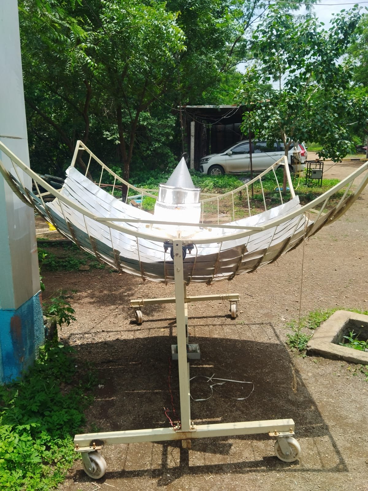
solar still - integrated water distillation system using a parabolic dish solar collector
Introduction
As part of our renewable energy project, we have been exploring the possibility of utilizing concentrated solar thermal energy for essential applications: freshwater production. The project aims to develop an integrated system that can harness solar energy through a parabolic trough collector and utilize the collected thermal energy for solar distillation. The primary objective is to maximize the utilization of available solar energy while addressing important challenge —sustainable and clean water generation.
17/06/2026
Existing Solar Collector Assessment
Collector Specifications
- Aperture Width: 205 cm
- Collector Length: 205 cm
- Depth: 50 cm
- Aperture Area: Approximately 4.20 m²
- Adjustable Tilt Mechanism: Available
- Receiver Support Structure: Available
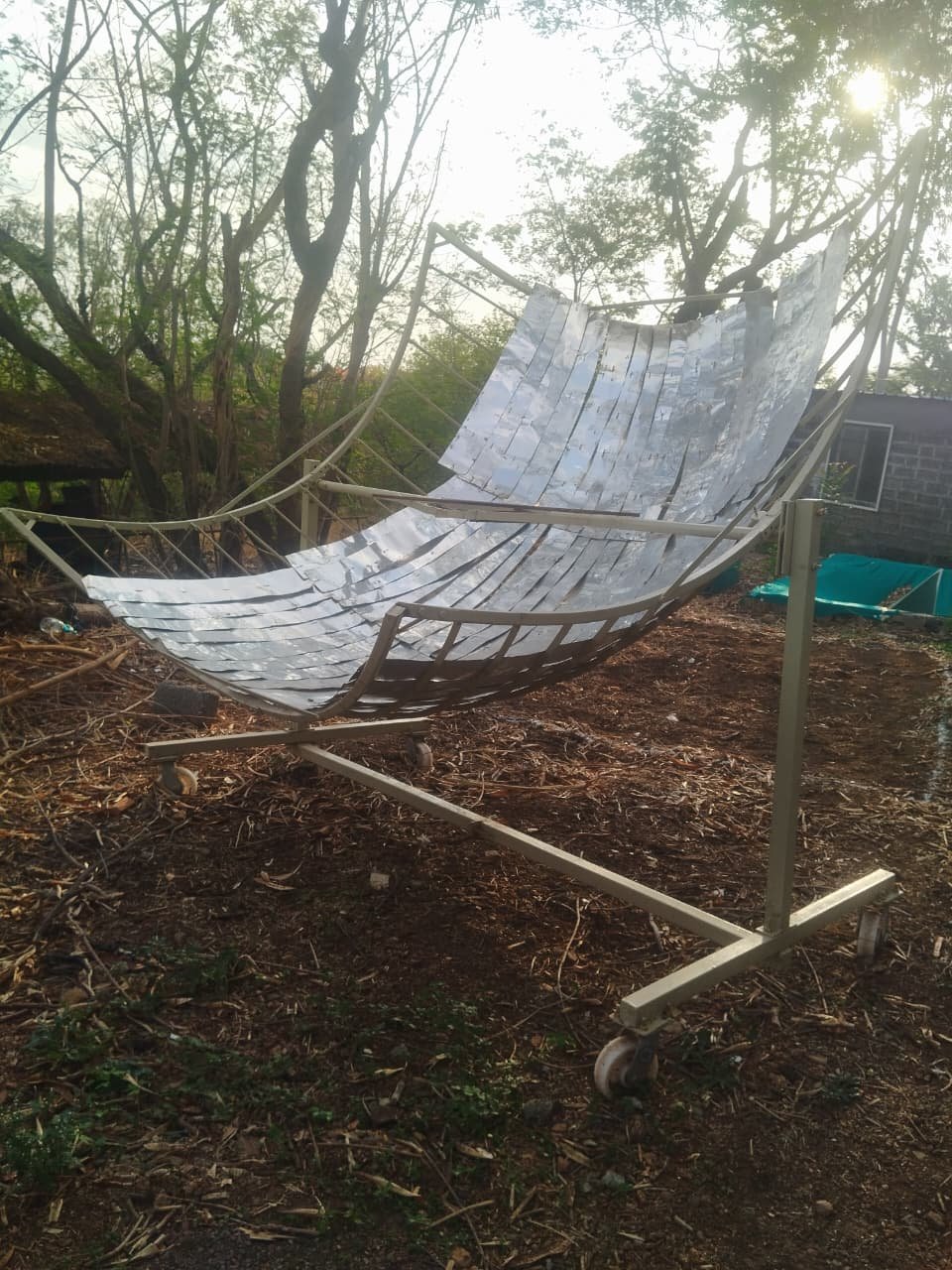
Instead of constructing a new collector from scratch, the team decided to refurbish and reuse the existing structure. This approach significantly reduces project cost while promoting sustainable engineering practices through equipment reutilization.
Structural Inspection and Analysis
An initial inspection of the collector revealed that the supporting framework remains structurally sound. However, several improvements were identified:
- Reflective surfaces require cleaning and replacement.
- Alignment of reflector panels needs verification.
- Focal line determination must be performed experimentally.
- Receiver mounting arrangement requires modification for improved thermal performance. The adjustable tilt feature of the collector is considered a major advantage, allowing manual solar tracking throughout the day.
Concept Development
13/06/2026-15/06/2026
solar still – performance table and industrial production Several conceptual designs were evaluated during the brainstorming stage. Initial Concept The original idea involved generating steam inside a solar still basin and passing the vapor through a condensation.
The proposed sequence :
Solar Collector → Basin Heating → Steam Generation → Condensation → Freshwater Collection.
Although innovative, further analysis revealed that this configuration would result in competition distillation processes because both require the heat carried by the steam.
Proposed System Architecture
1. Energy Collection Zone
The parabolic trough collector concentrates solar radiation onto a receiver tube located at the focal line.
Functions:
- Solar energy concentration
- Thermal energy collection
- Heat transfer to the working fluid
2. Distillation Zone
A solar still basin equipped with a copper heat-exchanger coil receives the remaining thermal energy.
Functions:
- Saline water heating
- Vapor generation
- Freshwater production through condensation
Engineering Design Development
Based on the collector dimensions, preliminary engineering sketches and CAD-style layouts were developed.
Key design features include:
- Copper receiver base positioned along the focal line
- Hot water circulation loop
- Heat-exchanger integrated inside the solar still basin
- Sloped and polished alluminium sheet condenser divider
- Distillate collection trough
The current design is sized around the available 205 cm × 205 cm collector and targets thermal support.
18/6/2026
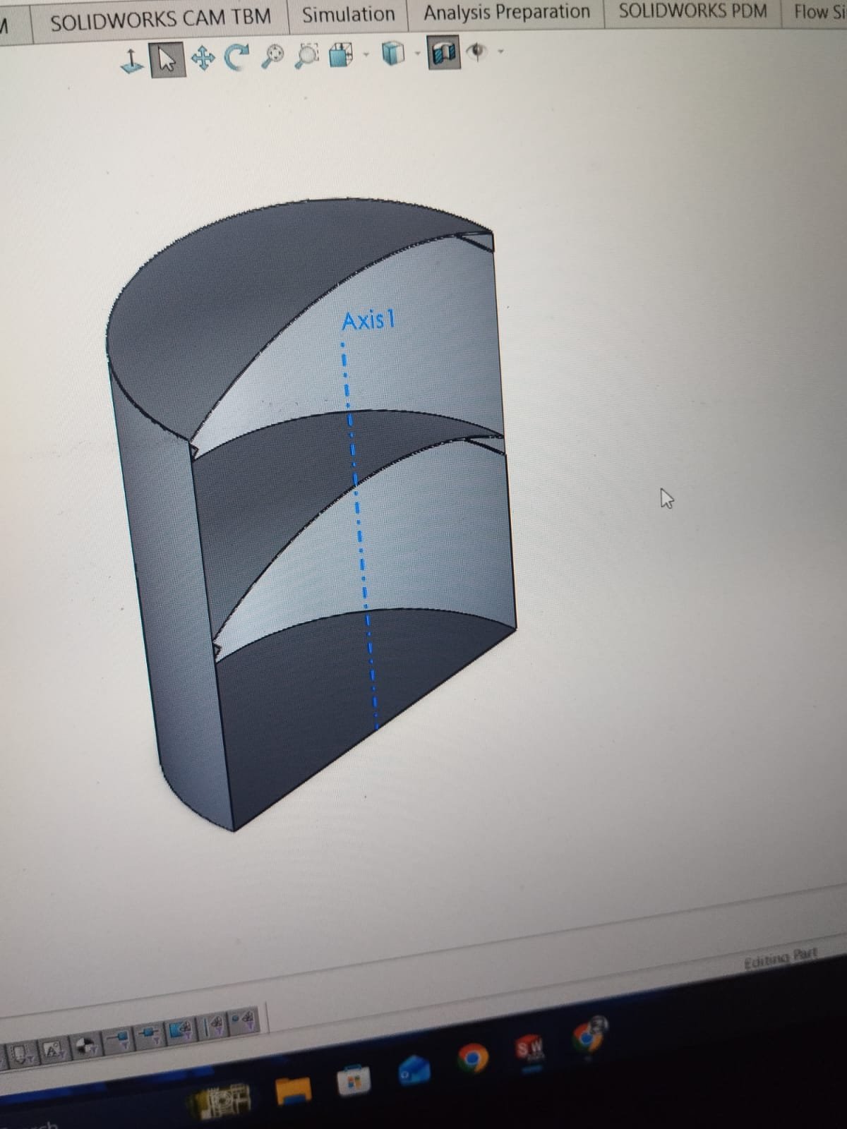
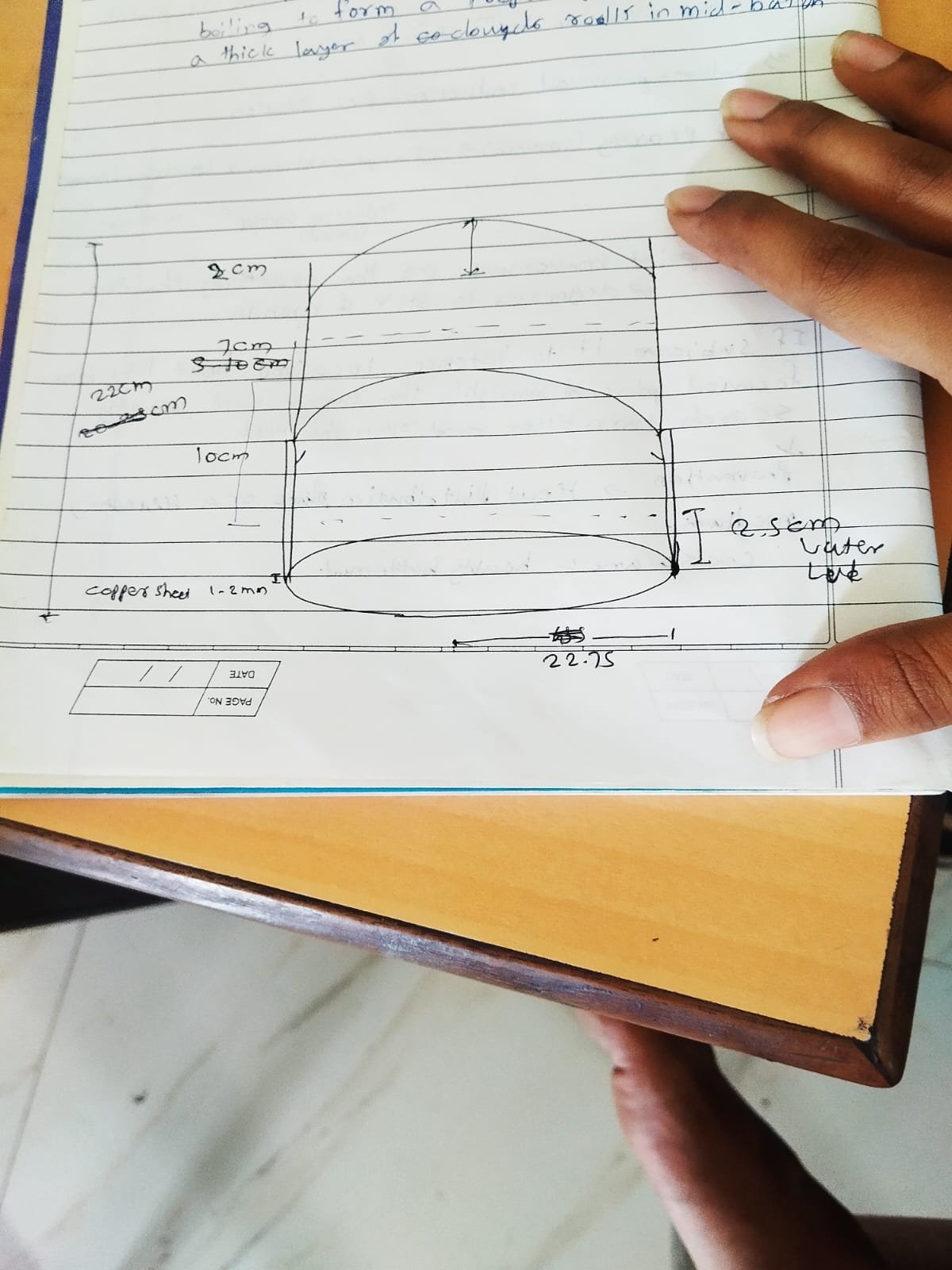
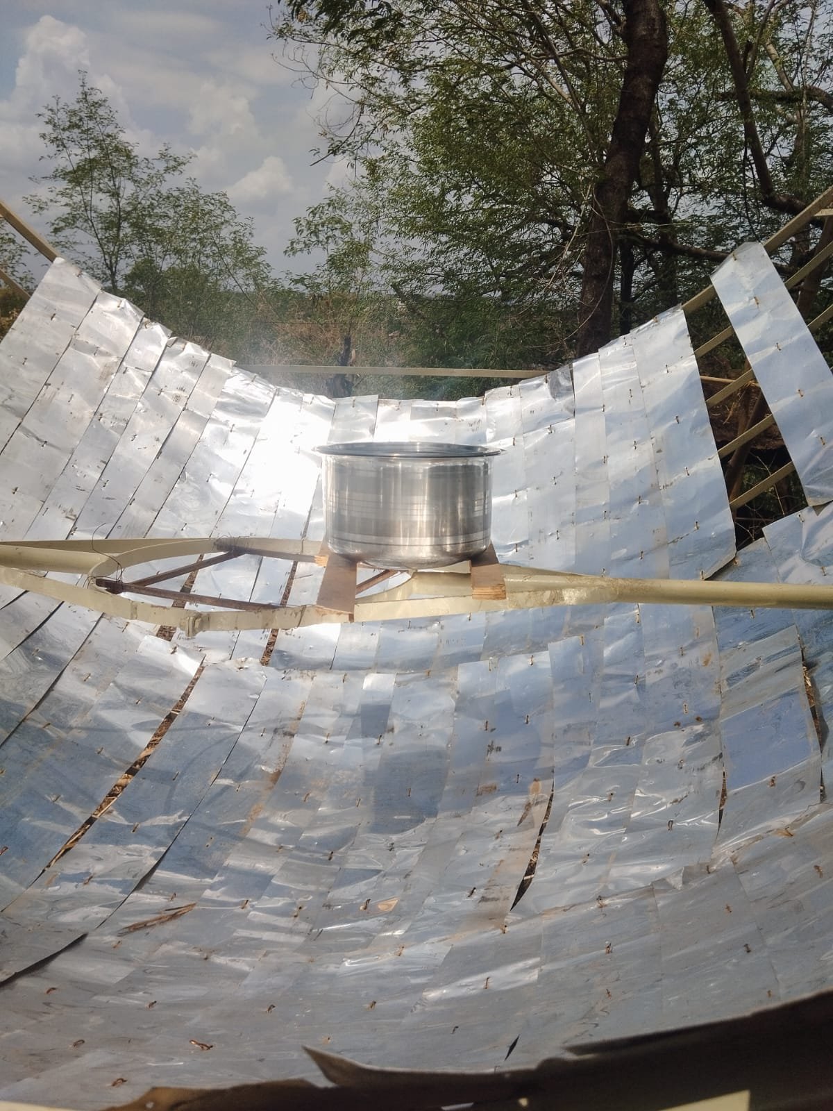
From the moment we drew up the first sketch, we ran into a massive thermodynamic problem: The Cooling Dilemma. If the upper chamber water heats up too much, the temperature difference between the hot steam below and the dome above disappears. The moment that happens, condensation stops completely, and the solar still turns into a useless pressure cooker.
Originally, we thought about using a 8-liter tank of static water on top just to act as a giant “heat sponge.” But a static tank will eventually overheat anyway, and adding 8 kg of dead weight to a moving, tracking solar dish is a structural nightmare. We needed a way to actively kill that heat without plugging into an electrical grid.
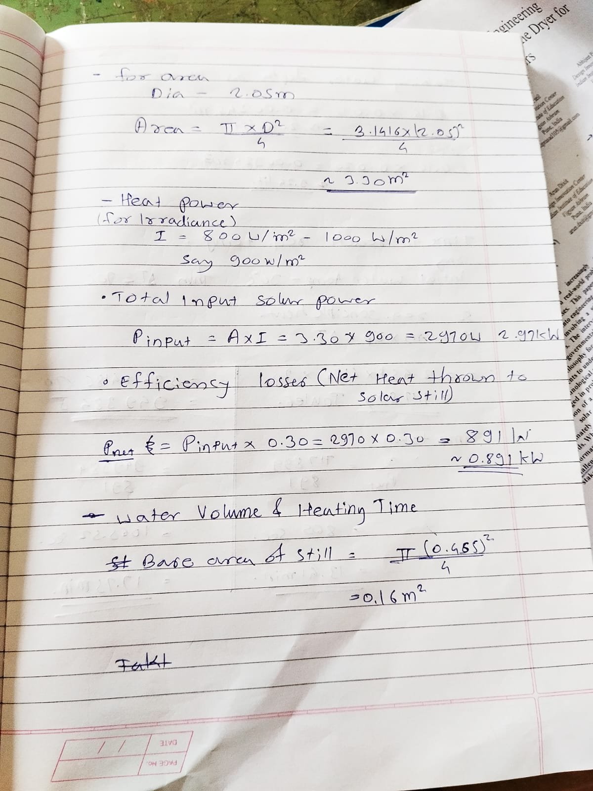
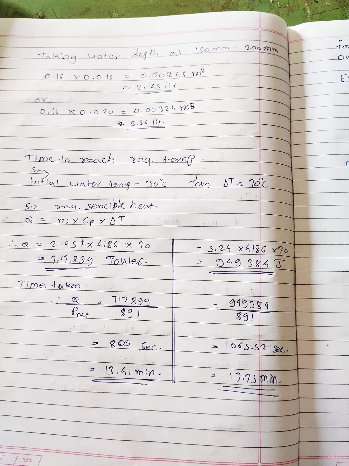
updated calculations and dimentions
26/06/2026
Once we decided to abandon the heavy multi-layer concept and focus entirely on maximizing a single-stage system, we hit another massive roadblock. We knew the upper cooling chamber had to stay cold, and we knew from our thermodynamic calculations that evaporative cooling was the secret weapon to achieve this.
1. The Submerged Bubbler Ring:We decided to mount a flexible, circular air bubbler ring at the absolute bottom of the upper chamber completely submerged under our 15–20 mm cooling water layer.
2. The Wind-Driven / Thermal Cowl Exhaust: If that newly created humid air just sits inside the upper chamber, the air will quickly become saturated (hitting 100% humidity), evaporation will stop, and the cooling effect will flatline. We needed a fan to continuously sweep that hot, humid air out and pull fresh, dry ambient air in.
self-regulating ecosystem: The harder the solar dish cooks the bottom copper plate, the more heat rises to the upper chamber. The more heat that enters the upper water, the faster the natural thermal draft becomes, spinning the cowl and venting the heat away.
27/6/2026
assembled the parabolic dish and mounted bearings. wanted to take the trial test through the water cantainer, but cause of wheather issue, can’t happen.
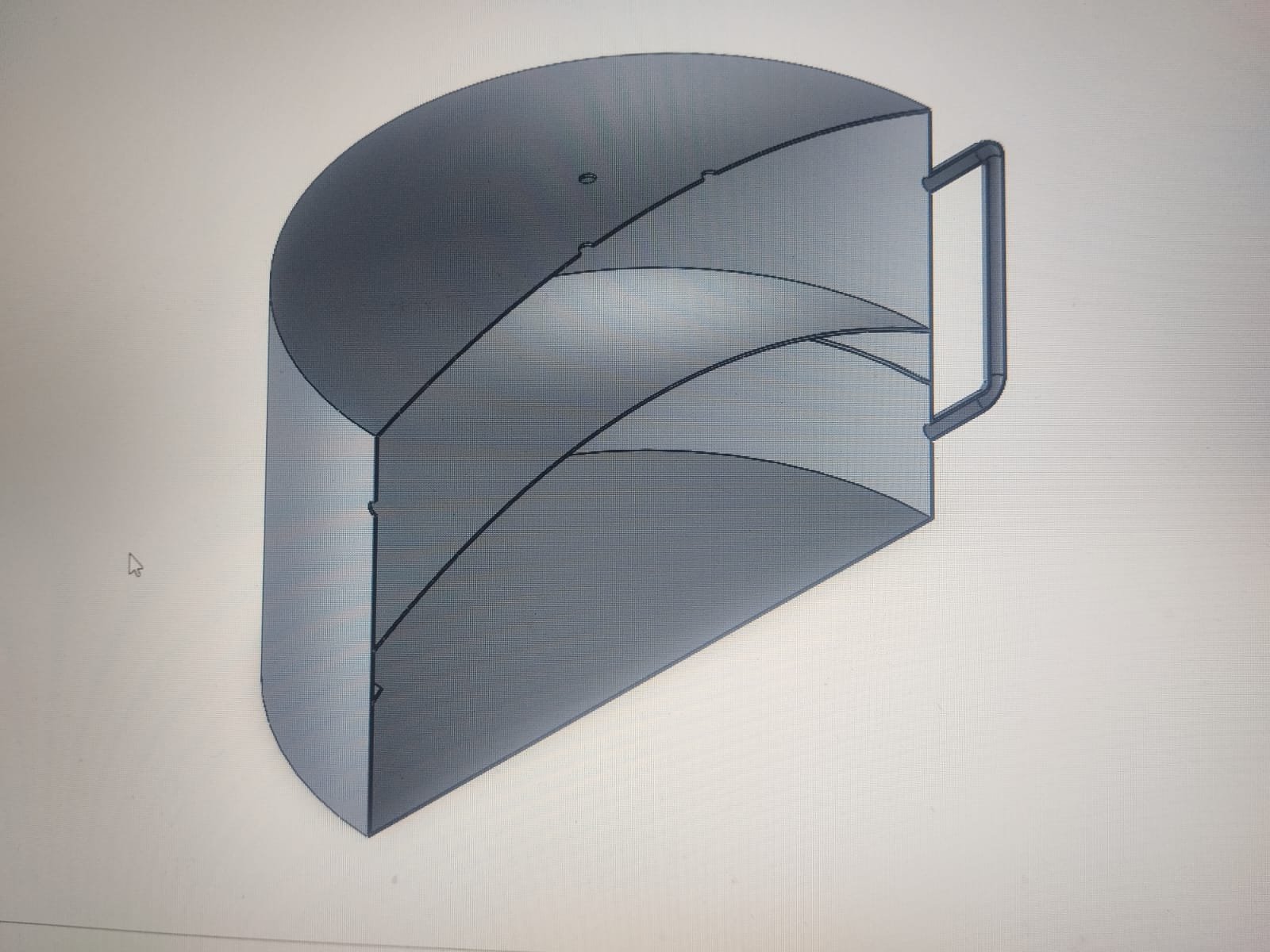
28/06/2026
updated the auto-CAD image
Working principle:
- Lower chamber = feed/evaporation chamber, heated from bottom by the dish
- Vapor rises and condenses on the underside of the aluminium dome (divider)
- Condensate runs down the dome’s slope to a collector ring
- Upper chamber holds 5 L of cooling water, which acts as a heat sink to keep the dome cool enough for condensation, while itself being preheated (regenerative preheating)
- Feed water drips from upper chamber to lower chamber via a saline-drip-style valve at a controlled ~19 ml/min (revised from 20), chosen specifically to avoid the thermal/level shock of a bulk dump
- Planned: metal bubbler ring in the upper chamber near the dome, intent still to be clarified (distributing feed water for heat exchange vs. air-mixing)
- Sun-tracking automation is being handled separately by a collaborator
Thermal input: Net heat delivered to the still ≈ 891 W
08/07/2026
The Water-Condensation Approach
The initial architecture of the distillation unit attempted to induce phase change by utilizing water as the primary cooling medium to condense the generated water vapor. However, experimental evaluation revealed a thermodynamic bottleneck: this configuration failed to utilize the system’s thermal power at its maximum level. To maximize thermal efficiency, the design was shifted toward a wind-condensing
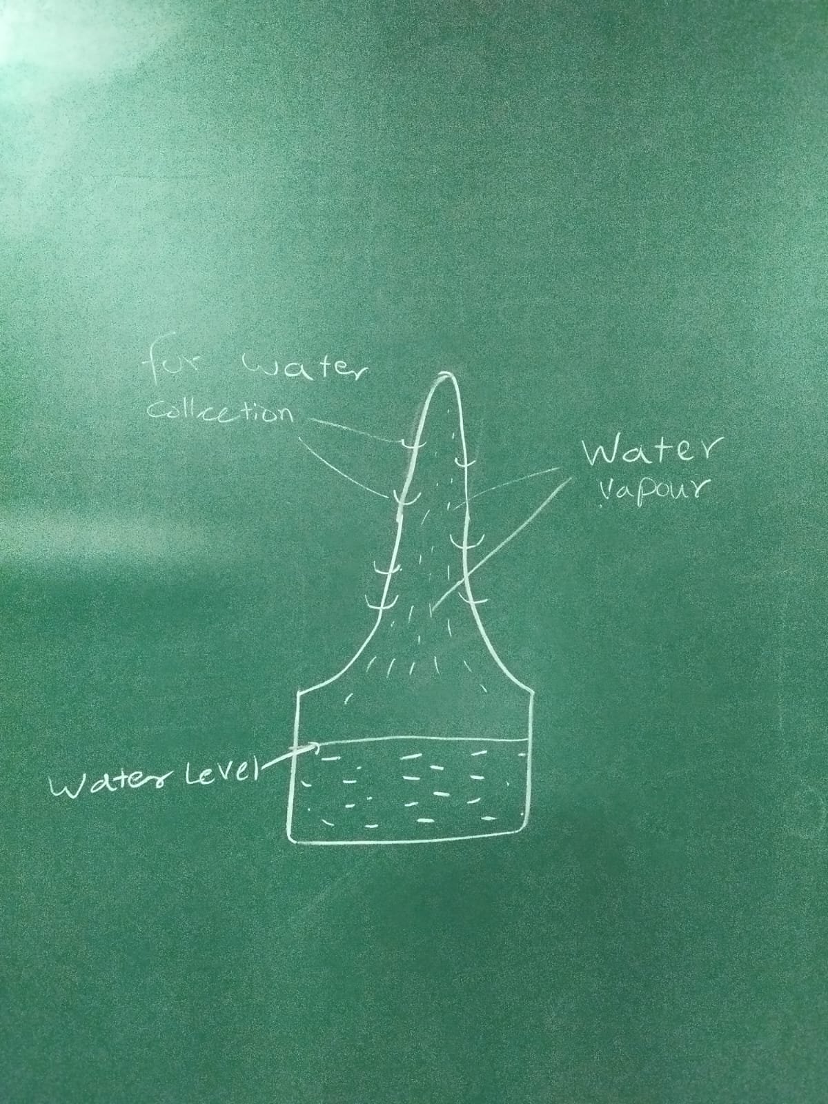
initial design
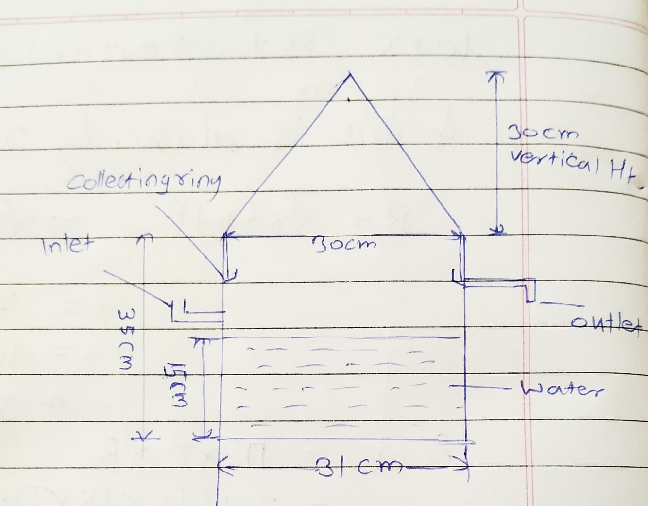
10/7/2026
ondensing Cone Geometry
-
Vertical Height (30 cm): Designed to provide a balanced structural pitch. This vertical height gives the cone an optimal slope, allowing gravity to cleanly drive dropwise condensation down into the collecting ring without letting droplets stall or prematurely precipitate back into the un-distilled fluid.
-
Base Opening Diameter (30 cm): Mapped to fit tightly over the internal diameter of the lower basin, ensuring that the rising saturated vapor flux enters the cooling zone without any escape.
2. Evaporator Basin Structure & Fluid Limits
-
Total Container Height (33 cm): The main body structure provides a deep operational chamber. This height leaves enough dead volume (headspace) between the maximum fluid boundary line and the collection ring to prevent active boiling splatters from contaminating the clean distillate pool.
-
Basin Outer Diameter (31 cm): Defines the fixed base used to balance our solar radiation inputs.
-
Maximum Raw Water Level (15 cm): Represents the maximum volumetric storage boundary capacity of the raw water reservoir
3. Interfacing and Fluid Control Lines
-
Concentric Collecting Ring (22 cm from the bottom): Profiled at the junction interface where the base of the condensing cone sits. It is strategically aligned just above the inlet structure to grab the downward condensate flow efficiently moving to outlet.
-
Inlet Port: Placed cleanly above the maximum fluid capacity line to allow smooth, uninterrupted replenishment of the raw matrix.
-
Outlet Plumbing Line: Positioned directly beneath the collecting ring trough floor, utilizing a gravity-fed pressure gradient to continuously evacuate clean distillate out of the system.
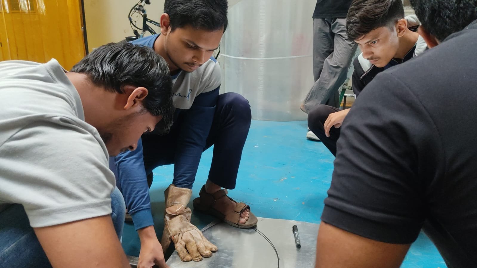
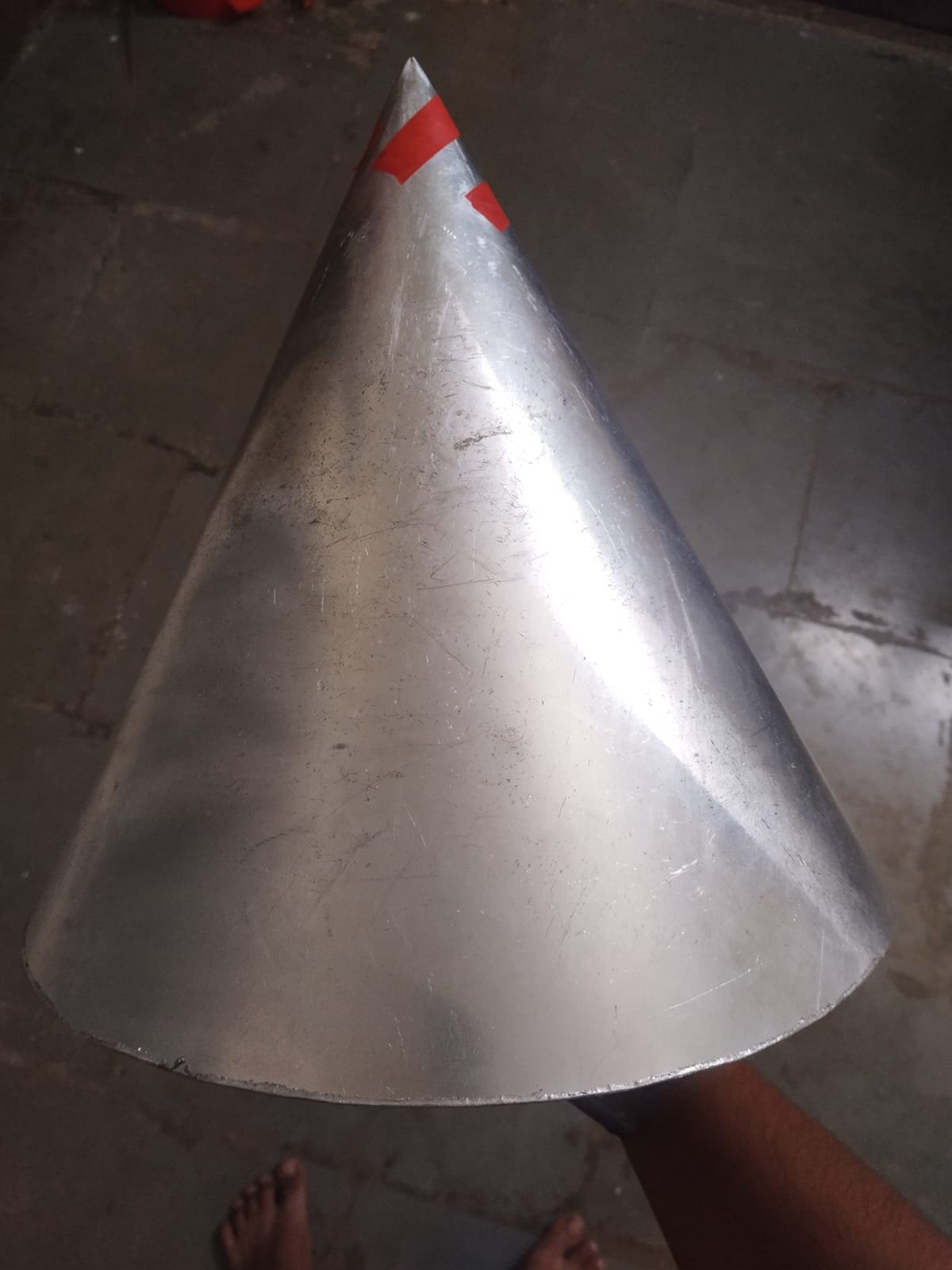
14/7-19/7
created conical shape
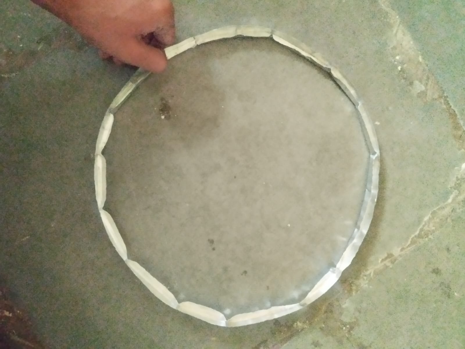
tried making collecting ring prototype
22/7-2/8
Inlet and Outlet Preparation
- Holes were accurately marked and drilled in the stainless steel container according to the finalized design.
- The water inlet was positioned above the operating water level (17 cm) to allow controlled water filling.
- The distilled water outlet was fabricated to provide smooth discharge of the collected condensate.
Condensate Collecting Ring Fabrication
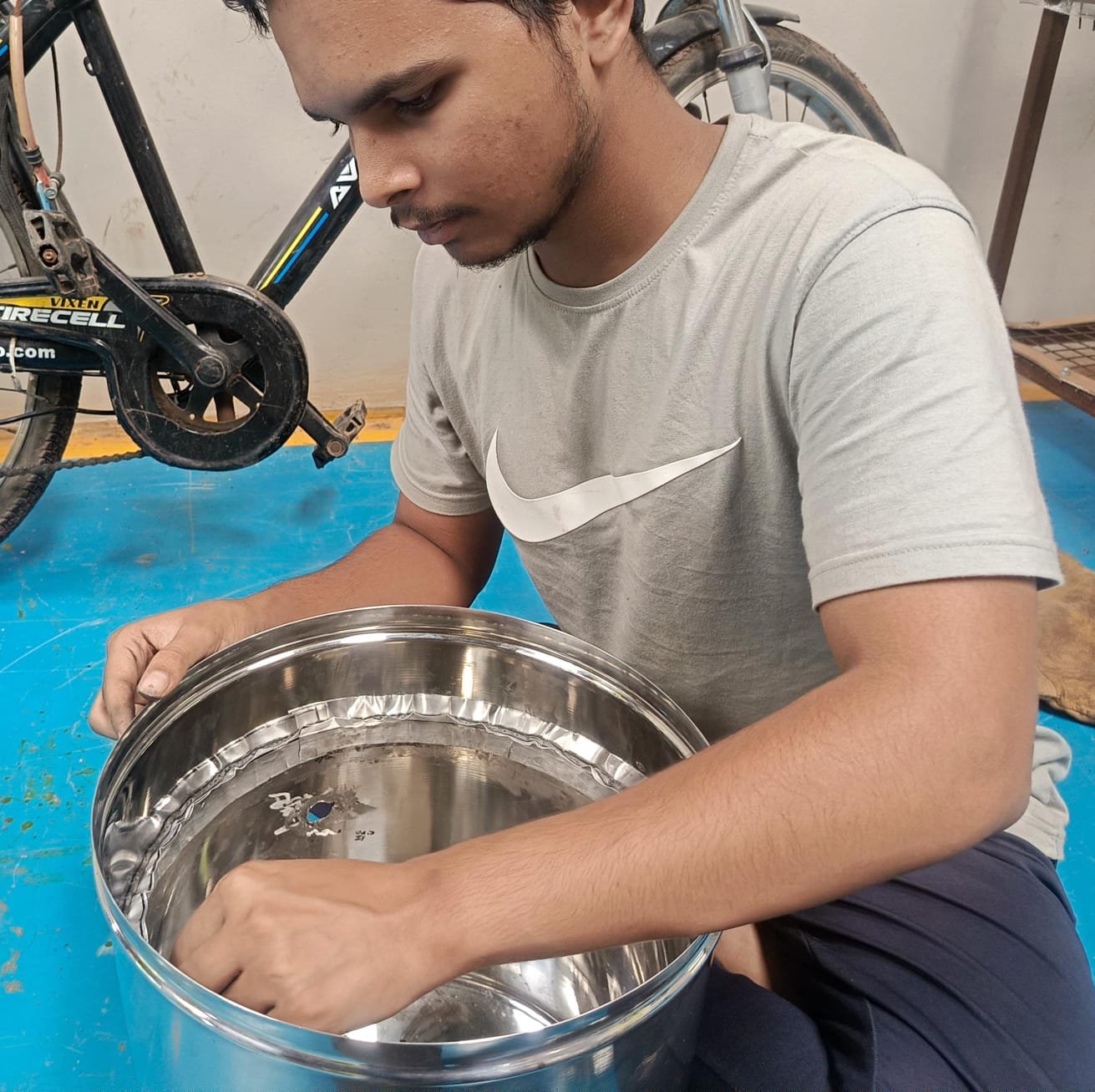
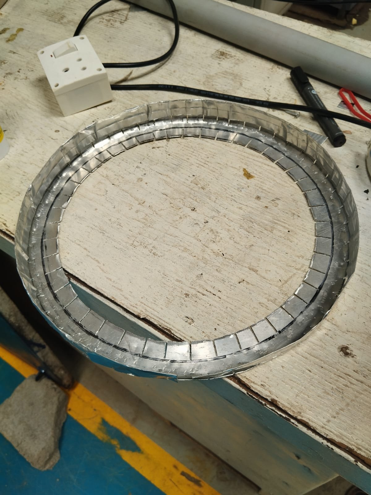
- A V-shaped condensate collecting ring was fabricated and installed inside the upper portion of the chamber.
- The purpose of this ring is to collect the condensed water droplets from the inner surface of the conical cover and guide them efficiently toward the outlet, minimizing water loss.
Thermal Insulation
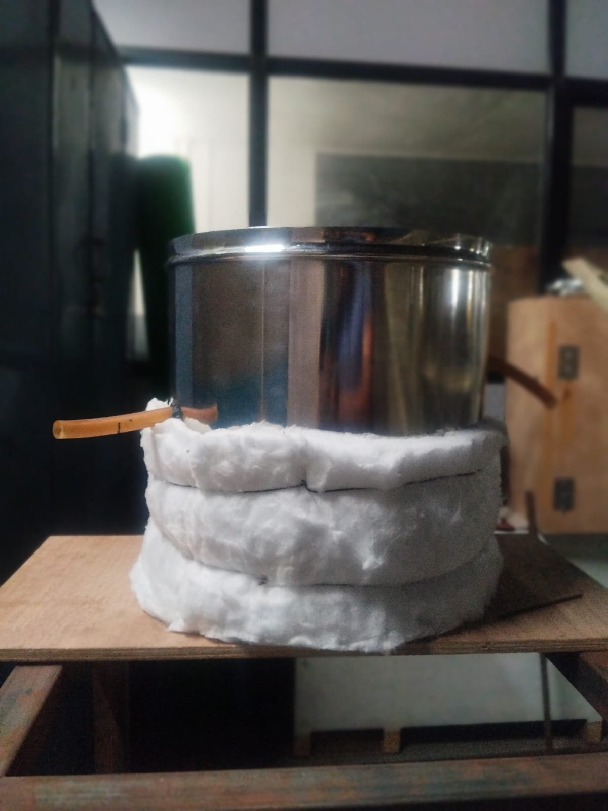
- Ceramic wool insulation was installed around the stainless steel chamber.
- This insulation helps reduce heat loss to the surroundings, improving thermal efficiency and maintaining a higher evaporation temperature inside the system.
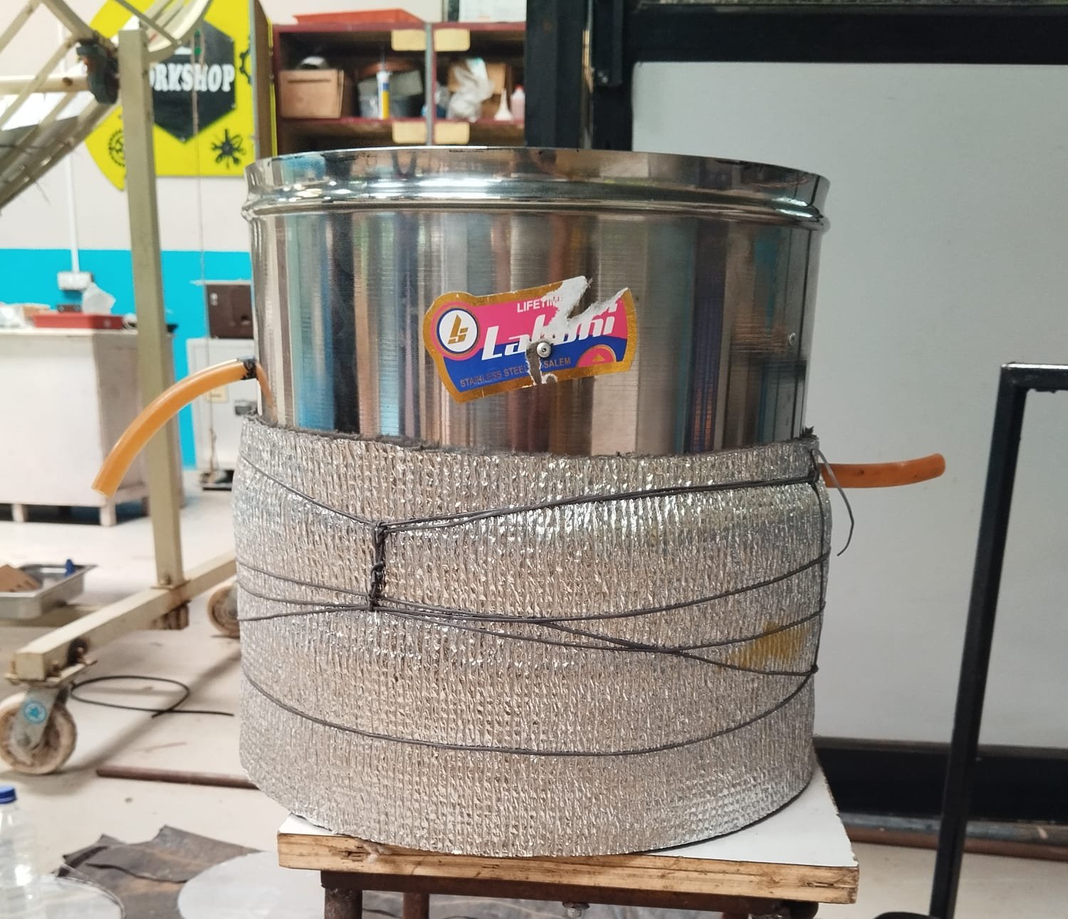
To minimize heat loss and maximize system efficiency, we executed a two-layer insulation strategy:
-
Primary Insulation (Ceramic Wool): We wrapped the SS container in high-temperature Ceramic Wool. This acts as our primary thermal barrier to trap heat inside the vessel.
-
Secondary Protection (Aluminum Foil Foam Insulation): To solve the practical issue of ceramic wool sagging or degrading over time, we encased it with an outer layer of Aluminum Foil Foam.
The issue
Once the main container was ready, we encountered a mechanical roadblock with the collecting ring:
-
The Problem: The collecting ring wasn’t sitting straight with the container as required for efficient condensate collection.
-
The Failure: It had been temporarily attached using standard M-Seal. Under handling and thermal expectations, the bond failed completely, and the ring fell off.
4/8/2026
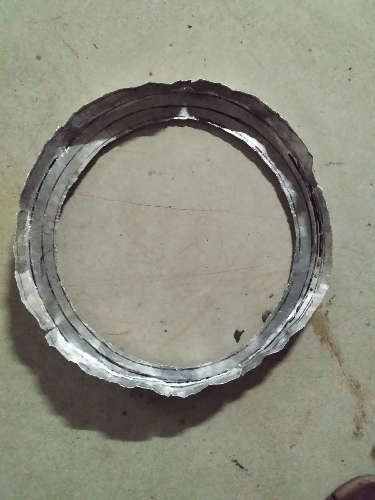
Fabrication of the Collecting Ring
-
Initially tried making a vertical circle shape, but it was difficult to maintain the required form.
-
So switched to a horizontal circle and used hammering to get the desired shape, the metal started bending unevenly.
-
Made small relief cuts to correct the bend, but the shape still did not meet our requirements, so this initial attempt was cancelled.
Revised Method and Attachment
-
Cut a horizontal strip with a 2 cm gap, which allowed us to bend and shape the ring smoothly into the required profile.
-
Using a rivet gun, we firmly attached the newly fabricated collecting ring to the main chamber.
-
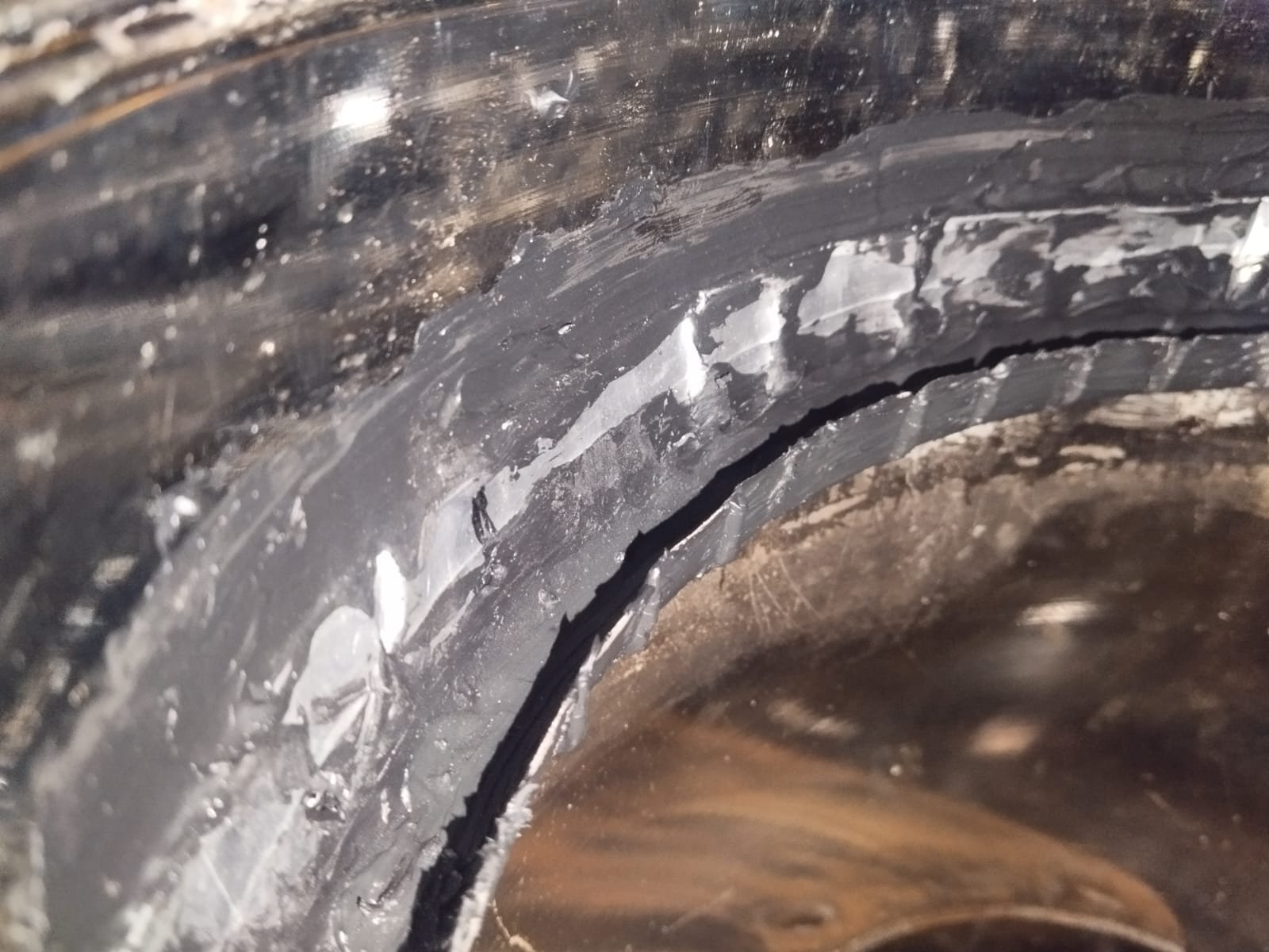
Then applied the sealant around the joints.
Leakage Testing
-
conducted leakage tests to verify that there were no gaps in the joints or around the collecting ring.
-
The sealant held up well, confirming the chamber was sealed and ready for thermal testing
18/8/2026
Controlled Thermal Performance Testing
-
To check whether the vapor forms and flows properly into the outlet, we tested the prototype using hot boiling water.
-
We conducted 3 separate test runs by pouring hot water into the container.
-
In all three tests, the steam successfully rose, condensed on the upper cone surface, dripped smoothly into the collecting ring, and exited through the outlet pipe as expected.
Outdoor Solar Testing
-
The weather seemed clear and sunny, so we placed the solar still outside to test it under natural sunlight.
-
Shortly after setting up, the weather changed unexpectedly, clouds blocked the sun, and the sunlight was lost.
-
Because direct heat was no longer available, the outdoor test had to be cancelled for the day.
26/8/2026
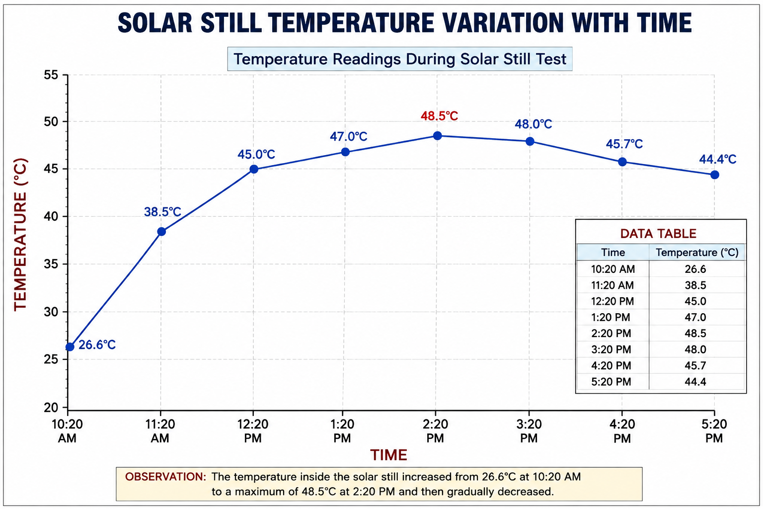
The temperature profile shows that the solar still was able to absorb and retain heat effectively during the peak sunshine hours. These observations will be useful for further evaluation of the system’s thermal performance and distilled water production.
Next step: Further testing will be carried out to measure the amount of distilled water produced and to evaluate the overall efficiency of the solar still

Design Modification to Increase Heat Capture Area
After discussing the design with Shreyash Sir and Ayushya, we decided to modify the lower section of the solar still. The lower portion of the insulation was cut down to expose a larger area of the bottom surface to solar radiation. The exposed area was then painted with a suitable dark-coloured coating to improve heat absorption.
This modification was made with the aim of increasing the effective heat-capture area and improving the amount of solar energy transferred to the water inside the solar still. The performance of the modified design will be evaluated during the subsequent testing.
.