Introduction:
I was given a task to design a Temperature & Humidity Control Panel using ESP32. The main goal is to make a system that can measure temperature and humidity, show the readings on a display, allow adjustment of a threshold temperature, and trigger a relay when the temperature goes above the set value.
The system uses an AHT2415C sensor for measuring, a 16×2 I2C LCD for display, two push buttons to change the threshold, and a 1-channel relay module for controlling external devices. The threshold is initially set to 30°C.
Components Used:
- ESP32 DevKit V1
- AHT2415C Temperature and Humidity Sensor
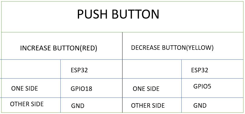
- Two Push Buttons (Increase & Decrease Threshold)
- 16×2 I2C LCD Display
- 1-Channel Relay Module
- Breadboard and wires for testing
- 3D-printed Housing
- Screws and Nut-Bolts
- 3 Pin Socket
Connections :
| 16*2(I2C) LCD | ESP32 |
| GND | GND |
| VCC | VIN |
| SDA | GPIO21 |
| SCL | GPIO22 |
| AHT2415C TEMPERATURE HUMIDITY SENSOR | ESP32 |
| VCC | 3.3V |
| GND | GND |
| SDA | GPIO21 |
| SCL | GPIO22 |
| 1-Channel Relay Module | ESP32 |
| IN | GPIO19 |
| VCC | VIN |
| GND | GND |
CODE :
#include <Wire.h>
#include <LiquidCrystal_I2C.h>
#include <Adafruit_AHTX0.h>

// -------- PIN DEFINITIONS --------
#define BTN_UP      18
#define BTN_DOWN    5
#define RELAY_PIN   19   // ACTIVE HIGH relay

// -------- OBJECTS --------
LiquidCrystal_I2C lcd(0x27, 16, 2);
Adafruit_AHTX0 aht;

// -------- VARIABLES --------
float threshold = 30.0;
float temperature = 0.0;
float humidity = 0.0;

// Button debounce
bool lastUpState = HIGH;
bool lastDownState = HIGH;
unsigned long lastButtonTime = 0;
const unsigned long debounceDelay = 200;

// Sensor timing
unsigned long lastSensorTime = 0;
const unsigned long sensorInterval = 500;

void setup() {
  Wire.begin(21, 22);

  lcd.begin();
  lcd.backlight();

  pinMode(BTN_UP, INPUT_PULLUP);
  pinMode(BTN_DOWN, INPUT_PULLUP);

  pinMode(RELAY_PIN, OUTPUT);
  digitalWrite(RELAY_PIN, LOW);   // Relay OFF initially

  if (!aht.begin()) {
    lcd.clear();
    lcd.print("Sensor Error");
    while (1);
  }

  lcd.clear();
  lcd.setCursor(0, 0);
  lcd.print("T:      H:    ");
  lcd.setCursor(0, 1);
  lcd.print("TH: ");
  lcd.print(threshold, 0);
}

void loop() {
  unsigned long now = millis();

  // -------- BUTTON UP --------
  bool upState = digitalRead(BTN_UP);
  if (lastUpState == HIGH && upState == LOW && now - lastButtonTime > debounceDelay) {
    threshold += 1.0;
    lastButtonTime = now;
  }
  lastUpState = upState;

  // -------- BUTTON DOWN --------
  bool downState = digitalRead(BTN_DOWN);
  if (lastDownState == HIGH && downState == LOW && now - lastButtonTime > debounceDelay) {
    threshold -= 1.0;
    lastButtonTime = now;
  }
  lastDownState = downState;

  // Update threshold on LCD
  lcd.setCursor(4, 1);
  lcd.print("   ");
  lcd.setCursor(4, 1);
  lcd.print(threshold, 0);

  // -------- SENSOR READ --------
  if (now - lastSensorTime >= sensorInterval) {
    lastSensorTime = now;

    sensors_event_t h, t;
    aht.getEvent(&h, &t);

    temperature = t.temperature;
    humidity = h.relative_humidity;

    lcd.setCursor(2, 0);
    lcd.print("    ");
    lcd.setCursor(2, 0);
    lcd.print(temperature, 1);

    lcd.setCursor(9, 0);
    lcd.print("    ");
    lcd.setCursor(9, 0);
    lcd.print(humidity, 0);
  }

  // -------- RELAY CONTROL (ACTIVE HIGH) --------
  if (temperature > threshold) {
    digitalWrite(RELAY_PIN, HIGH);   // Relay ON
  } else {
    digitalWrite(RELAY_PIN, LOW);    // Relay OFF
  }
}
Methodology
Electronics:
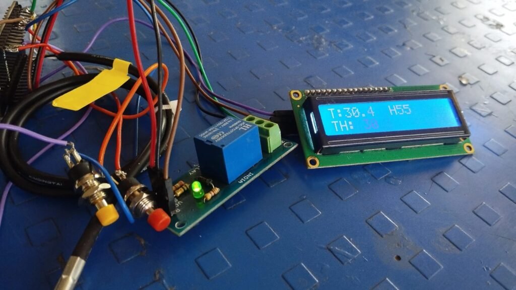
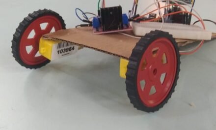
I first connected all components on Arduino to test the connections.
Then I shifted to ESP32 and used a breadboard to test the code and make the system work.
I faced some issues connecting the LCD, so I replaced it with another module.
After everything worked properly, I soldered all components to make it stable.
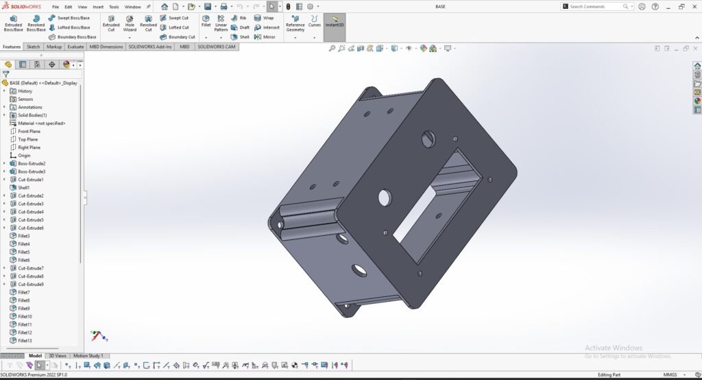
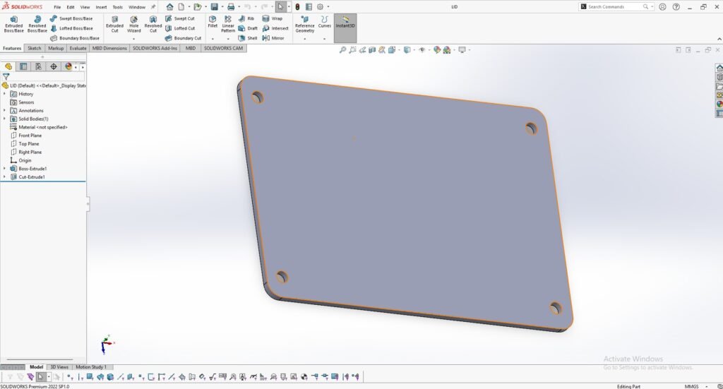
Housing Design:
Designing the housing was the most challenging part.
I first tried FreeCAD, but it kept hanging.
Then I learned SolidWorks from scratch and completed the design .
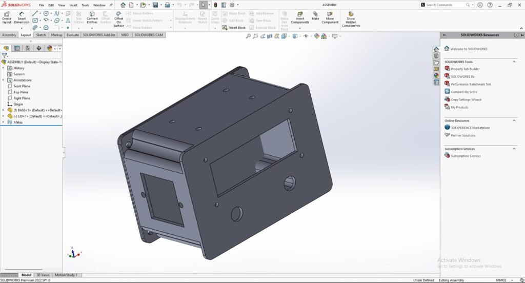
I measured all components , made their 3D models, and assembled them in the case.
I applied constraints to restrict all movement(6-DOF).
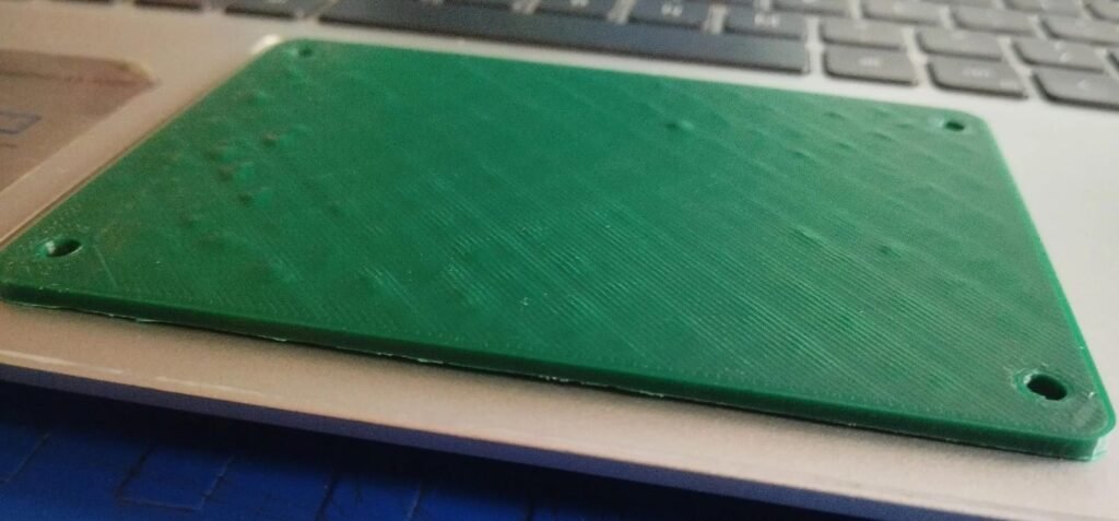
3D PRINTING:
The case and lid were printed using the Fracktal Works printer.
Before printing, the SolidWorks design file was first converted into an STL file. The STL file was then processed in Ultimaker Cura software to generate the G-code required for 3D printing.
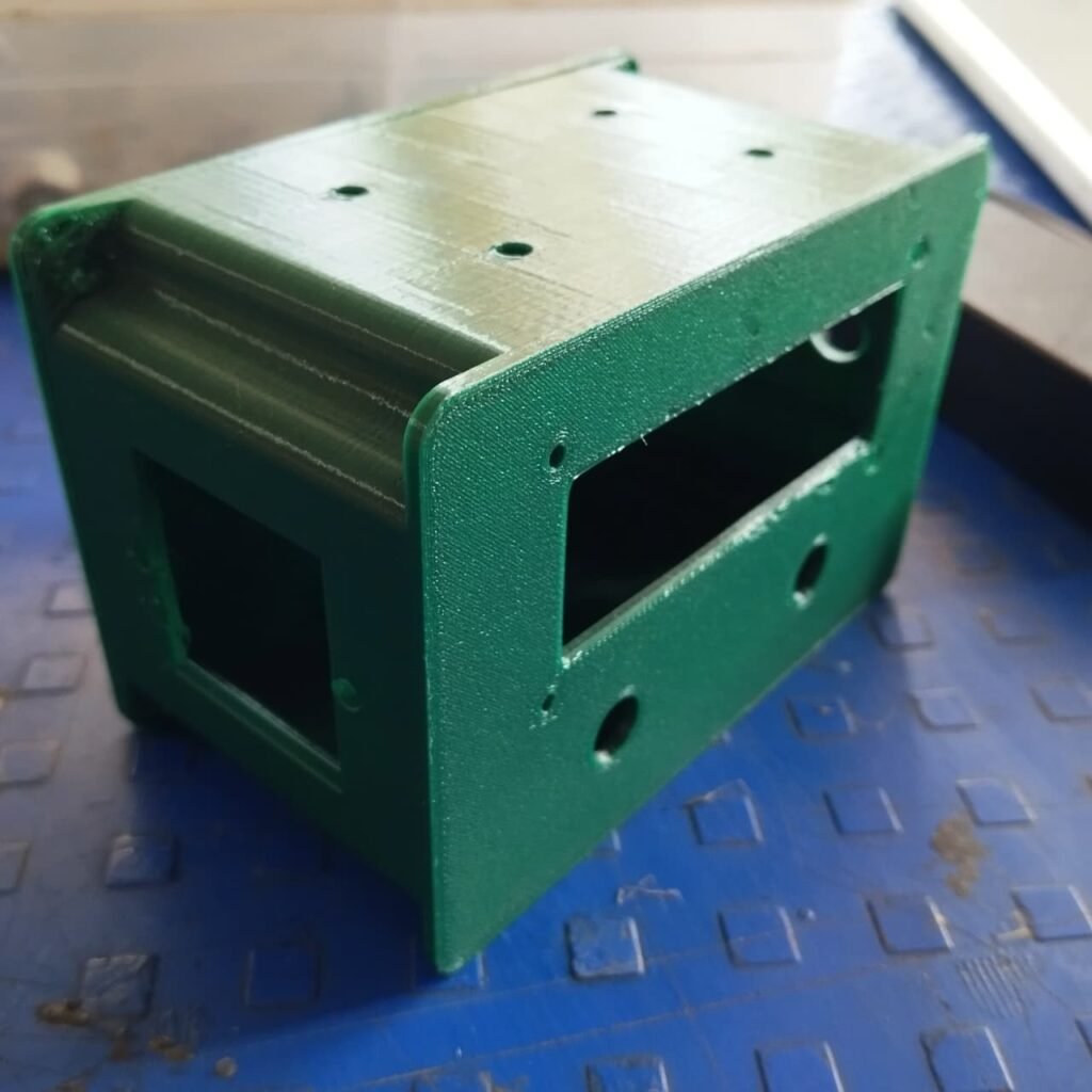
Assembly of Components:
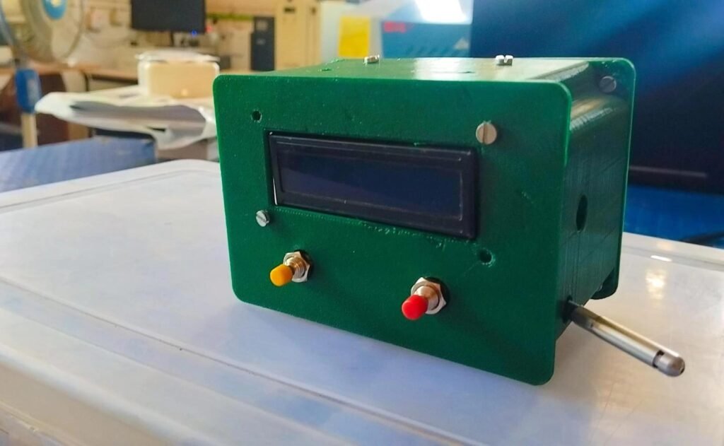
After completing the 3D printing of the case and lid, I started assembling all the components into the enclosure.
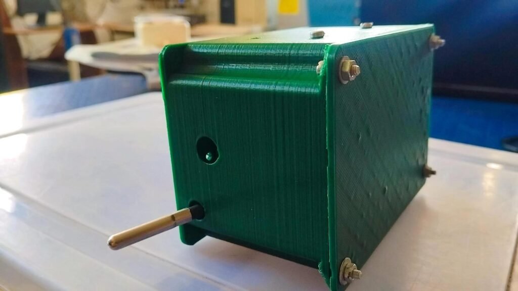
First, the LCD display was fixed on the front panel using screws. Then, the two push buttons were mounted properly on the front side for easy access. The sensor probe was placed through the side opening so that it can measure temperature and humidity from outside the enclosure.
Inside the case, the ESP32, relay module, and wiring were arranged properly to ensure a compact and neat setup. All components were secured firmly, and the lid was closed using nut-bolts.
The final assembly gives the control panel a clean and structured appearance.
Working Demonstration:
After completing the assembly, the system was powered on to check its functionality.
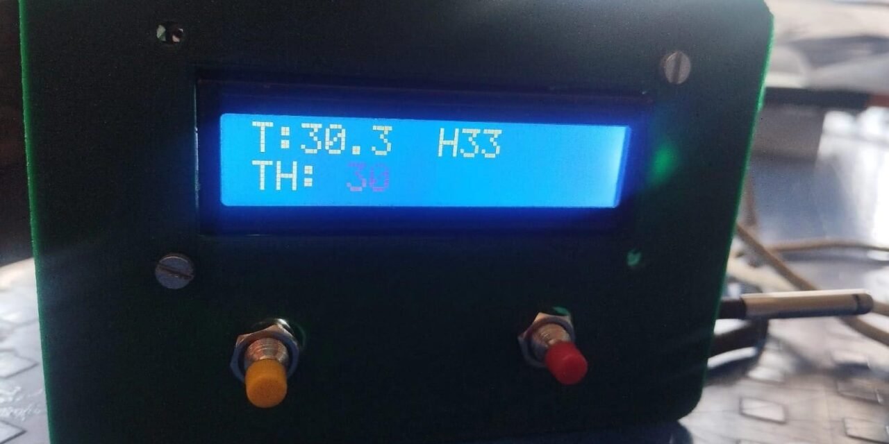
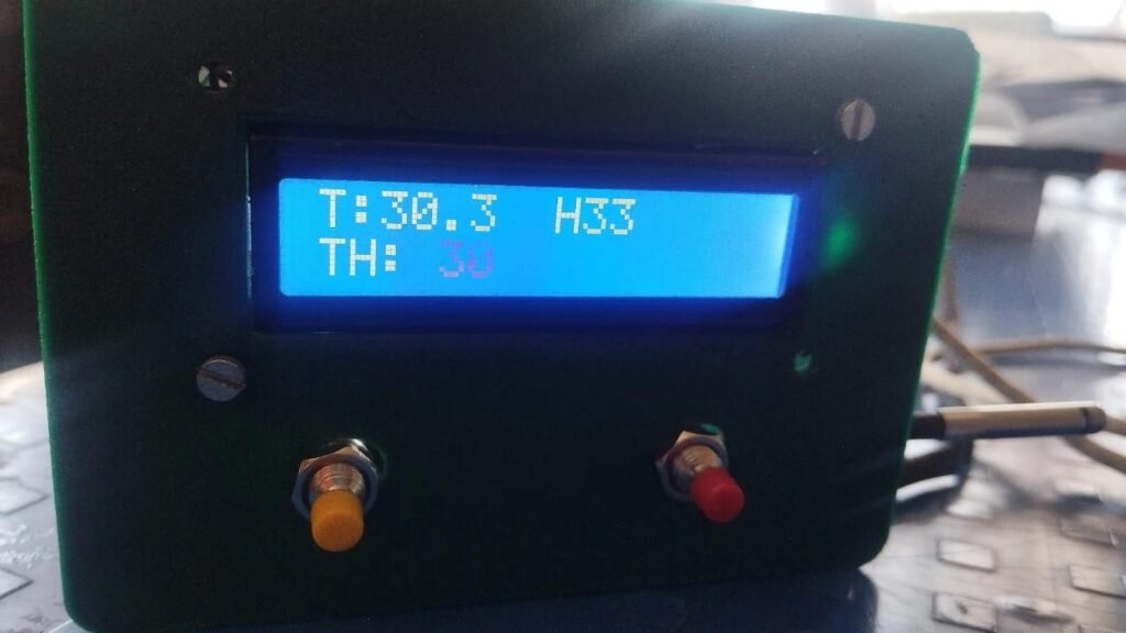
The LCD display shows:
- Current Temperature (T)
- Humidity (H)
- Threshold Temperature (TH)
The push buttons are used to increase and decrease the threshold temperature. When the measured temperature exceeds the set threshold value (30°C), the relay gets activated.
The image below shows the working condition of the control panel with live temperature and humidity readings displayed on the LCD.
Conclusion:
The Temperature and Humidity Control Panel was successfully developed using ESP32. It measures environmental conditions, displays the readings, and activates a relay when the temperature exceeds the set limit. This project provided practical experience in embedded systems and hardware development. The system can be further improved in the future.

