Executive Summary:-
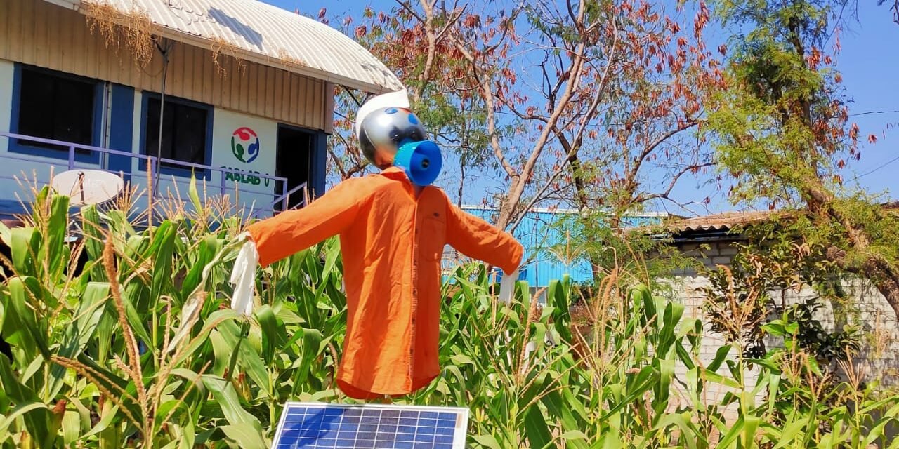
Agriculture today is about so much more than a farmer simply planting a seed. It takes a whole ecosystem and a host of actors to work together to produce the food we need for a population of more than seven billion people. This complex agricultural production system has evolved over time through scientific discoveries and other innovations. Advances in technology and farming practices have helped farmers become much more productive, growing crops efficiently in areas most suitable for agricultural production. So we have designed a product to nurture the common needs of farmers. Our Product is Smart Scare Crow for protection of crops from Birds and Wild Animals.
Background:-
A scarecrow is a decoy or mannequin, often in the shape of a human. Humanoid scarecrows are usually dressed in old clothes and placed in open fields to discourage birds from disturbing and feeding on recently cast seed and growing crops. Scarecrows are used around the world by farmers, and are a notable symbol of farms and the countryside in popular culture.

Requirement:-
Traditional scarecrow being a low cost model is widely is used by farmer, but it has less effect because birds after some time get used to it and they don’t have fear any more, and even in the nights when wild animals enter the field they don’t matters a standing mannequin till its make some scaring sound.
Also when discussing with farmers about their problem related with farming we know that most of the open farm fields farmers are having threat of Wild Animals being destroying their crop, and its very difficult and costly to keep a labor in farms for this work.
Solution:-
So understanding all this problems that framers faces we have designed a Smart Scarecrow ,
It is a digital innovation in traditional method of crop protection.
• Purpose of the solution:- A Smart Scarecrow is a Humanoid structure place at some place in farm which makes scary sound and does some motion.
• Scope of the solution :- We have tried to designed and manufacture this model in very low cost and affordable to common farmer also. This can we easily place in farm and self sustainable to operate itself.
Working:- The scarecrow is mounted using its metal pole in a field. It can be mounted anywhere in the open as it dose’nt require any external power supply. The solar panels constantly charge the battery of the system during day time. The DC motor is powered which rotates and so does the entire arm mechanism. The rotation of motor shaft rotates the gear connected to it which sets in motion the Linked arm mechanism. The mechanism allows for moving the arms in a human like motion vertically to imitate a human presence. Also the controller operates a speaker module to make some noise so hat birds and animals in near the field too are scared. Thus the system puts forth a modern solar powered scarecrow to protect farms from birds and animals.
“Our vision is to improve the farming output and reduced the farmer effort for a sustainable agriculture by offering technological innovation to our hardworking farmers”.
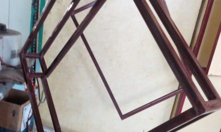
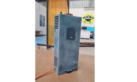
Concept CAD Model and Mechanism Structure:-

List of Material Required:-
- 6 mm Plywood – 2.00 Sq Ft
- 1.75 mm PLA Filament for 3D printing – 50gms/20mtrs
- 12V BO Motor-1 nos
- Red and Black Wire 0.5 mm diameter – 1 meter
- Nut and Bolts M8*10- 8Nos
- Acrylic Sheet 6mm for Gear Cutting.
- StyroFoam Sheet 18mm -6sq ft
- 50W Megaphone Loudspeaker-1 Nos
- 12v 10W Solar Panel-1 Nos
- Relay Timing Circuit Module.
- Air Tight Sealed Plastic Container Box- 1 Nos.
- 1″ inch Hollow MS Pipe – 7 ft
- 1/2″ inch Sq Tube- 4 ft
- DC Power Jack Pair- 1Nos
- 12V 1.5ah Rechargeable battery
- 8 in Dia Plastic Ball for Making Face of Scarecrow.
Step By Step Procedure:-
- Designing of Mechanism in 2D software.
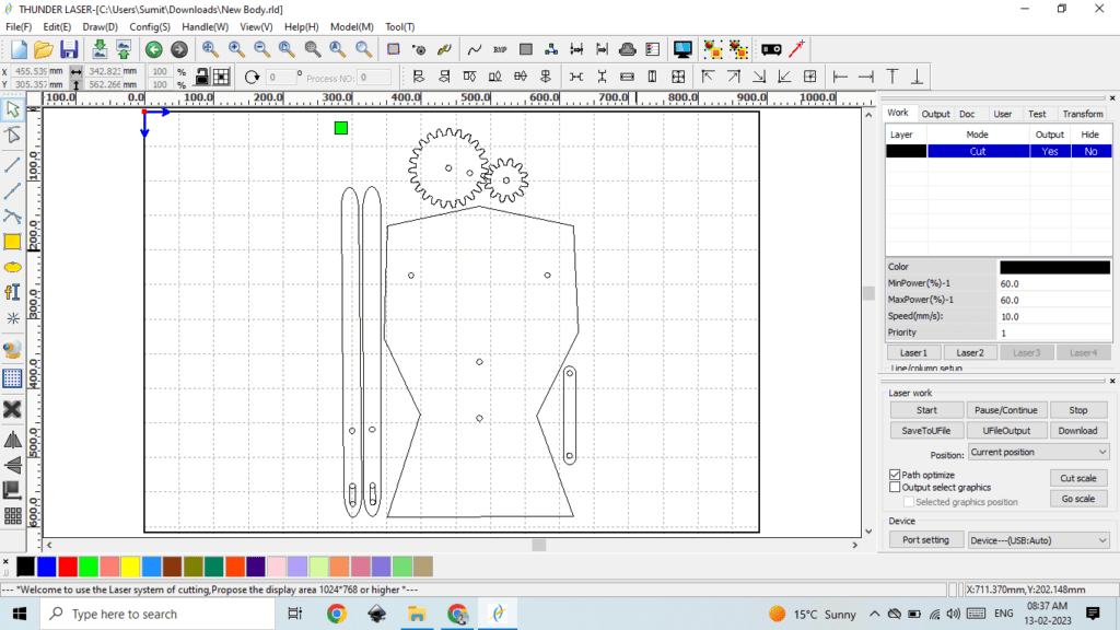
You can refer the .ai File for Laser Cutting. I have used RD works for Laser Cut designing.
2. Set the desired parameter of Power & Speed for Laser Cutting Machine as per material and machine setting.
I have set power 60 and speed 10mm/s for our 70W SIL Laser.
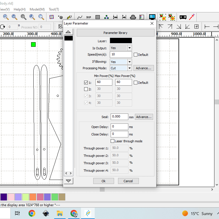
3. Switch On the Laser Cutting machine and upload the file in the system firmware. Open the file from the File Tab and press enter. DO NOT switch on the Laser tube.
4. Now take a Plain ply sheet without any bend or previous cut, place it on the platform of laser cutting machine and clamp it properly, now set the origin point and frame the cutting area.
5. Now Close the Door Panel of machine , then switch ON the laser tube and compressor and start cutting the sheet.
6. After the cutting is done, turn off the laser tube and compressor, wait till all the smoke is exhausted from the Fan and the open the door panel, remove all the clamping and take out you laser cutted parts.
7. Now Place all the part of table and assembled it with the Nuts & Bolts. Your Mechanism is ready now. Lets Automate it, attached the motor from the backside of Mainbody and mounted the small gear on it as shown in image.
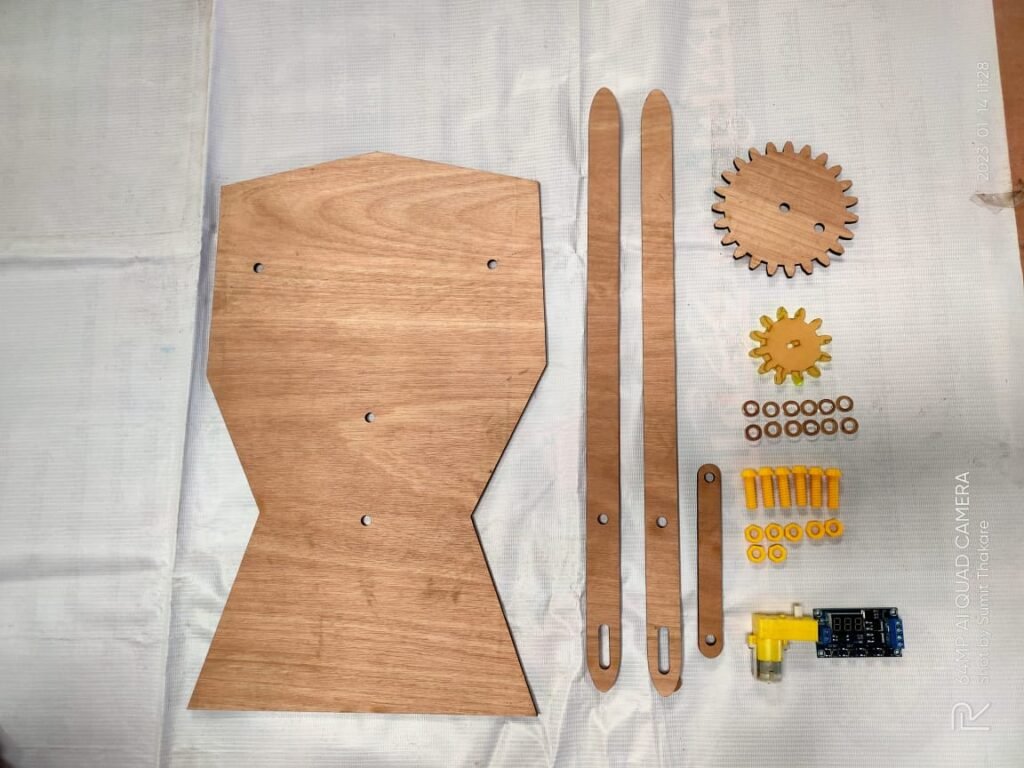
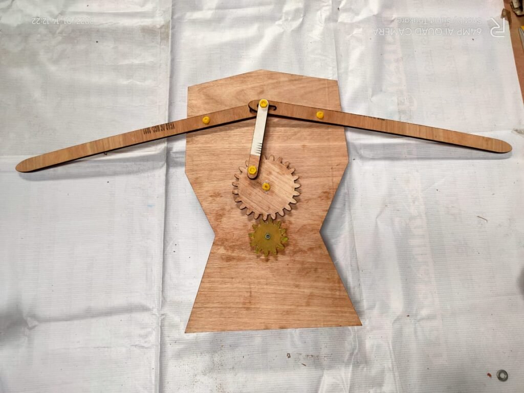
8. The mechanical part is finished, now lets move towards electronics.
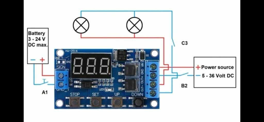
9. For automation and controlling the hand motion of scarecrow, I have used delay timing circuit module(HW-0516 Dual-MOS Trigger Cycle Circuit Timer Delay Module) , which trigger the circuit at particular time interval.
Procedure to SET Delay timing circuit :-
The following abbreviations are used for the Timer Module.
OP : open
CL : closed
LOP : cycles (loops)
OFF: off (emergency)
ON : on
C-P : sleep mode on
0-d : sleep mode off
000 standard view
There are 7 different programs, each performing different functions. These programs are hereinafter
referred to as “program numbers”.
with OP function P1.1, P1,2, P1.3, P-2, P3.1, P3.2, P-4
with OP und CL function P-2, P3.1, P3.2,
with OP, CL and LOP function P3.1, P3.2,
To program in the following settings, switches A1 and B2 must be included in the circuit. C3 is
optional. It is very difficult and can even be dangerous to make these settings without these switches
(Explanation YouTube video).
Setting program no.’s P1.1, P1,2, P1,3, P3.1, P3.2 und P-4
Activation or changing to another program number:-
Once the electrical connections and the necessary switches have been set up, activation can be
started.
- To do this, switches B2 and C3 need to be switched on.
- The active program number on the display flashes three times e.g. P-4.
- What is shown on the display depends on the pre-settings.
- After the flashes the display will show “standard view”.
- Press the SET button for 2 – 3 seconds to set the program numbers.
- One of the numbers mentioned above is now shown on the display – e.g. P-4.
- Select the desired program number by using the Up and Down buttons.
- Use P1.1 as an example.
- Once the desired number has been selected, press SET for 2 – 3 seconds.
- The display flashes three times and P1.1 is visible.
- After the flashes the display will show “standard view”. Now P1.1 is saved.
- To check, repeat by pressing SET for 2 – 3 seconds.
- Now P1.1 should be displayed. To get back to “Standard View”,
- Press SET for 2 – 3 seconds. The display flashes three times and P1.1 is visible.
- After the flashes the display now shows “standard view”
- This procedure can be used for all program numbers.
Setting up the relay operations OP, CL and *LOP
Op Mode
LOP Mode (cycles) can only be used with programmes P3.1 and P3.2.
The desired programme number has to be activated if you want to edit the control times.
Programme number P1.2 will be used as an example, and the OP mode will be edited.
- Once an electrical connection has been made and switched on, the display flashes three times
- and program P1.2 is visible.
- once the flashing has stopped, the display reverts to “standard view”).
- Press the SET button for 2 – 3 seconds.
- Now P1.2 is visible on the display screen.
- Press SET briefly and the display will flash 3 times in OP mode.
- Once the flashing has stopped the display changes to the current OP value e.g. 017 seconds.
- Set the desired time value e.g. *005 seconds by using the Up and Down buttons.
- *(Please note the information on additional functions on page 12, setting time parameters).
- If the value 005 seconds is set, press the SET button for 2 – 3 seconds.
- The OP value 005 has been saved.
- Next the display will flash three times and P1.2 will now be displayed.
- Once the flashing has finished, the “standard view” will be visible on the display.
- You can check the OP value by pressing the SET button briefly.
- First off the display will show the OP mode and then show the 5 second value.
- Once you’ve checked this the display reverts to “standard view”.
- This procedure can be used for all program.
CL mode:
- For programme P-2, you need a CL value.
- Programme numbers P3.1 and P3.2 need a cycle value (LOP) as well.
- In order to edit the control time of the relay, the desired programme number needs to be activated.
- Programme number P-2 will be used as an example. Modes OP and CL will be edited.
- Once an electrical connection has been made and switched on the display flashes three times and
- the programme number P-2 is visible.
- Once the flashing has finished “standard view” is visible on the display.
- Press SET for 2 – 3 seconds.
- Now P-2 is visible on the display screen.
- Press SET briefly and the display flashes three times in OP-mode.
- After the flashing has finished the display changes to the current OP value.
- e.g. 005 seconds – this can be kept or discarded as (the CL value will be edited).
- Press SET again briefly and the display flashes three times in CL mode.
- Once the flashing has finished the display changes to the current CL value, e.g. 013 seconds.
- Set the desired value e.g. 020 seconds using the Up and Down buttons.
- *(Please note the information on additional functions on page 11, setting time parameters).
- Once 020 seconds has been selected, press SET for 2 – 3 seconds.
- Now the CL value of 020 seconds is saved.
- Next the display will flash three times and programme P-2 is visible.
- Once the flashing has finished the display will show “standard view”.
- You can check on the OP and CL values by pressing the SET button briefly.
- The display shows the OP mode first and then 005 seconds.
- Next the display shows the CL mode and its value of 020 seconds.
- Once you’ve done your check the display reverts to “standard view”.
- This procedure can be used with programmes P-2, P3.1 and P3.2.
LOP Mode
The LOP mode can only be used with programmes P3.1 and P3.2.
To edit the control times of the relay the desired programme number has to be activated.
P3.1 is used as an example. The mode LOP is to be edited.
- Once an electrical circuit has been made and turned on, the display flashes three times and programme
- no. P3.1 is displayed.
- Once the flashing has finished, the “standard view” is visible on the display.
- Press the SET button for 2 – 3 seconds. Programme number P3.1 is visible on the display.
- Press the SET button briefly and the display will flash 3 times in OP mode.
- After the flashing has stopped the display changes to the current OP value.
- e.g. 005 seconds. This can be kept or discarded as (the LOP value will be edited).
- Press the push button SET briefly again and the display flashes 3 times in CL mode.
- Once the flashing has stopped the display will change to the current CL value e.g. 020 seconds. This
- can be kept or discarded as (the LOP value will be edited).
- Press the SET button briefly again and the display will flash 3 times in LOP mode.
- Once the flashing has stopped the display will show the current LOP value e.g.013 cycles.
- Set to the desired LOP value by using the Up and Down buttons e.g. *003 cycles.
- (Please note the information on additional functions on pages 12 and 13 Note 1).
- If 003 cycles have been selected, press the SET button for 2 – 3 seconds.
- Now LOP value 009 cycles is saved. The display next flashes 3 times and programme number P3.1 is
- visible. Once the flashing is over, the “standard view” is visible on the display.
- The OP, CL and LOP values which have been saved can be checked by briefly pressing the SET
- button. The display changes to OP mode and 005 seconds appears on the display.
- Then the display shows the CL mode and its value of 020 seconds.
- Then the display shows LOP mode and its value of 003 cycles.
- Once you’ve done your checks the display changes to “standard view”.
- This procedure can be used for programmes P3.1 and P3.2.s.
Continued……..

