Development of a Cooling Chamber for Black Soldier Fly
Introduction
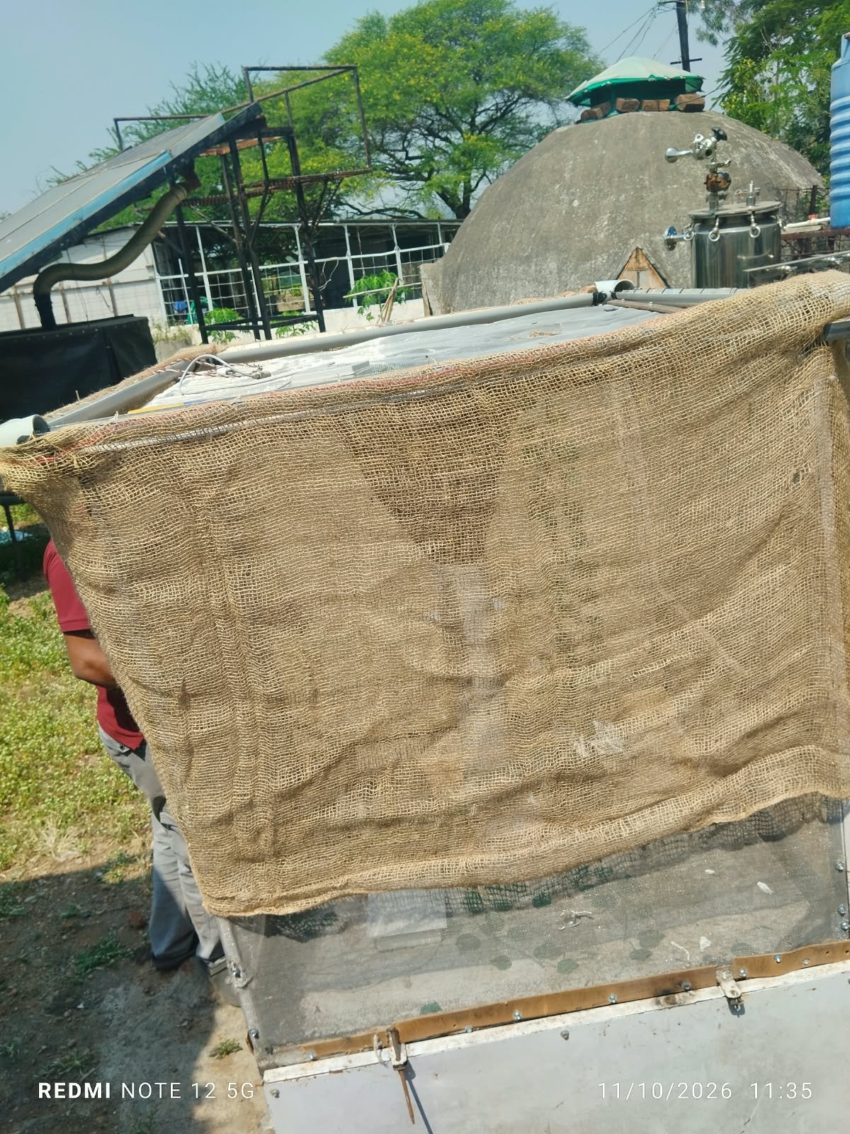
I was assigned to the project, focused on developing a cooling chamber for Black Soldier Fly (BSF). The main objective of the project was to develop a practical cooling arrangement that could reduce the temperature of the air entering the chamber and create a more suitable environment for the BSF.
The initial concept was based on evaporative cooling, where water would be supplied to a wet material surrounding the chamber. As air passes through the wet material, evaporation of water can reduce the air temperature before it enters the chamber.
Initial Concept: Rope-Based Cooling System
The first approach considered was to create a wet rope covering around the chamber. The idea was to provide water from the top so that the rope material would remain wet.
As air passes through this wet layer, water would evaporate and remove heat from the passing air. The cooled and humidified air would then enter the chamber, helping to reduce the internal temperature.
During the initial discussion with the supervisors, it was also explained that there were other possible approaches that could be explored if the rope-based system was not practical.
The three possible approaches considered were:
- Wet rope cooling system
- Raining or water-spray system
- Airo tube bubbler system using a water tank
The objective was not to immediately select one method, but to evaluate all three approaches from an engineering and practical point of view.
1. Wet Rope System
In this approach, a suitable porous material would be arranged around the chamber and continuously supplied with water from the top.
The wet material would act as an evaporative cooling surface. Air entering the chamber would pass through the wet layer, allowing heat transfer and evaporation to reduce the incoming air temperature.
This was selected as the first approach to prototype because it was relatively simple and could potentially be constructed using easily available materials.
2. Raining / Water-Spray System
The second approach discussed was to develop a raining or water-spray system around the chamber.
In this method, water would be distributed over the cooling surface using a suitable arrangement of spray nozzles. The objective would be to maintain a continuously wet surface and improve water distribution compared with manually wetting the material.
This approach could potentially provide more uniform wetting, but the water-distribution system and its overall design would need to be developed
3. Air Bubbler System
The third approach involved placing a water tank below the chamber and using an air tube or aeration pipe inside the water.
Air would be passed through the water in the form of bubbles. As the air interacts with the water, it would become cooler and more humid. The cooled and humidified air could then be directed upward into the chamber.
This approach was also considered because it could provide controlled air movement and humidification without requiring a wet external covering around the entire chamber.
26-27/9
Development of the Rope-Based Prototype
As the first approach, work was started on the rope-based cooling system.
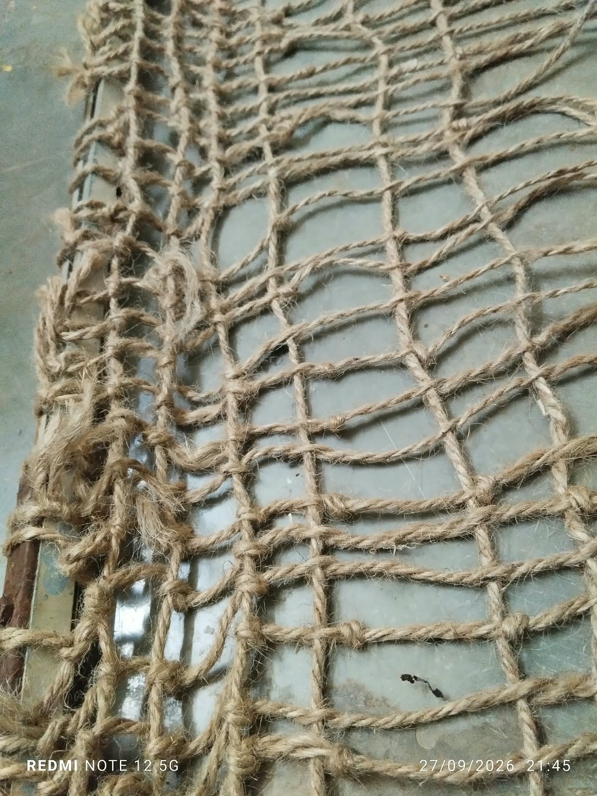
The initial prototype required the rope or cotton material to be manually arranged around the chamber. During fabrication, it was observed that preparing the covering manually required considerable time.
Another problem was maintaining a uniform shape and tightness of the covering. The manually prepared sections did not always have the same dimensions, resulting in variations in spacing and tension.
Because the arrangement was not sufficiently uniform, maintaining consistent contact between the wet material and the incoming air became difficult.
This highlighted an important engineering requirement: the cooling material should not only be capable of holding water but should also allow sufficient airflow through the cooling layer.
28-30/9
Trial with Commercial Mesh Bags
To reduce fabrication time and improve consistency, an alternative was discussed with Mahesh Sir and Dixit Sir.
Instead of manually constructing the rope covering, commercially available mesh bags used for storing onions or peanuts were considered as a possible replacement.
The advantage of using such bags was that they were readily available, easier to handle, and could potentially reduce the time required to fabricate the cooling structure.
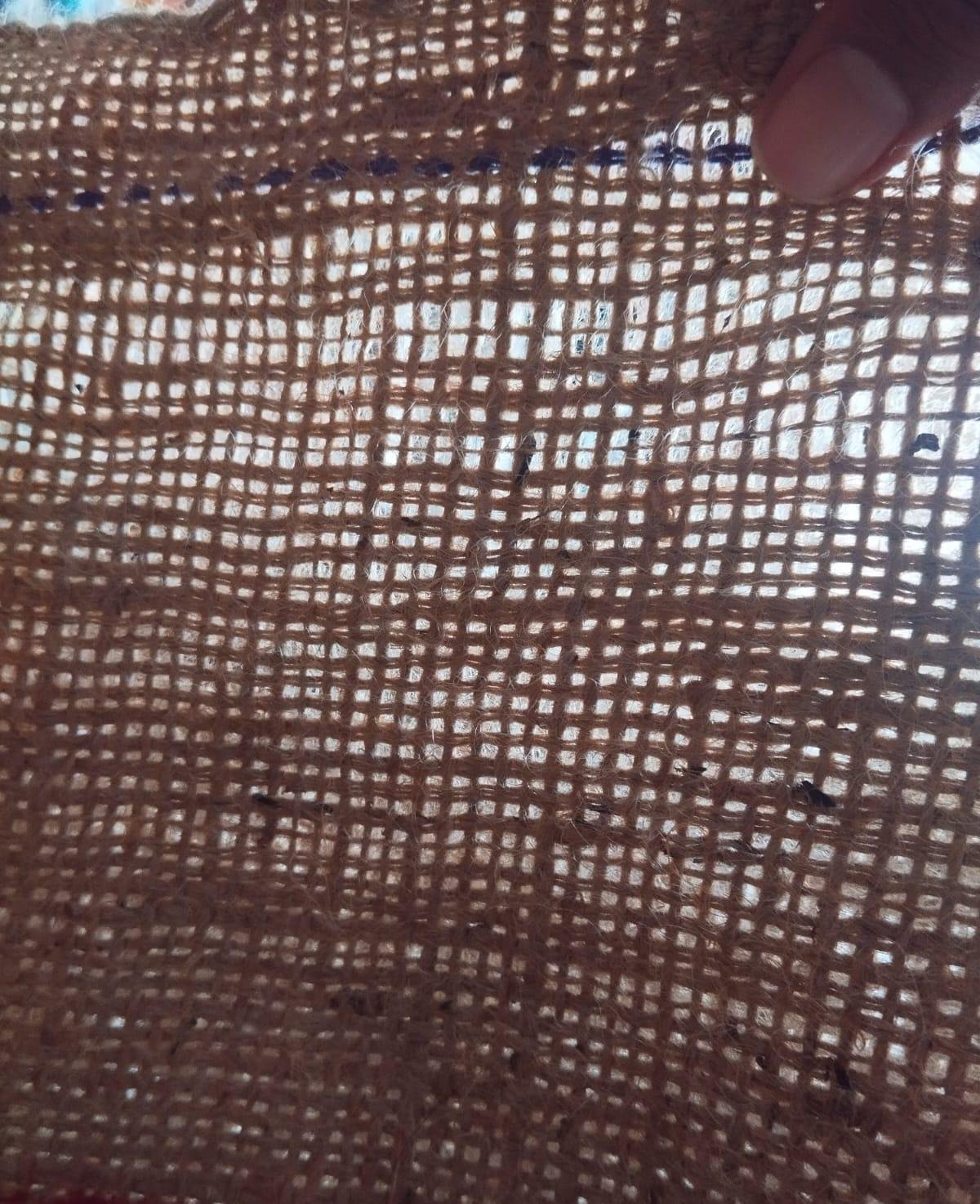
However, The mesh material of the available bag was relatively thick and had unsuitable spacing. Because of the construction of the material, the required amount of air could not pass through the cooling layer easily.
If the air entering the chamber is restricted, the cooling effect may not be sufficient even if the material remains wet.
Therefore, simply using an easily available mesh bag was not considered sufficient without further evaluation of its mesh size, thickness, air permeability, and water-holding capacity.
2/10
To increase the opening size and improve airflow, I manually cut alternate threads from the mesh using a cutter. This increased the spacing between the threads and improved the structure to some extent. However, the major limitation was that manually modifying the mesh was very time-consuming.
Therefore, after discussing the issue with the supervisors, I started looking for alternative mesh materials that could be directly used in the chamber. Some commercially available options were also checked online. However, the mesh available online had openings of approximately 5 cm, which were too large for the intended application. Such large openings could result in insufficient water retention and poor wetting of the material.
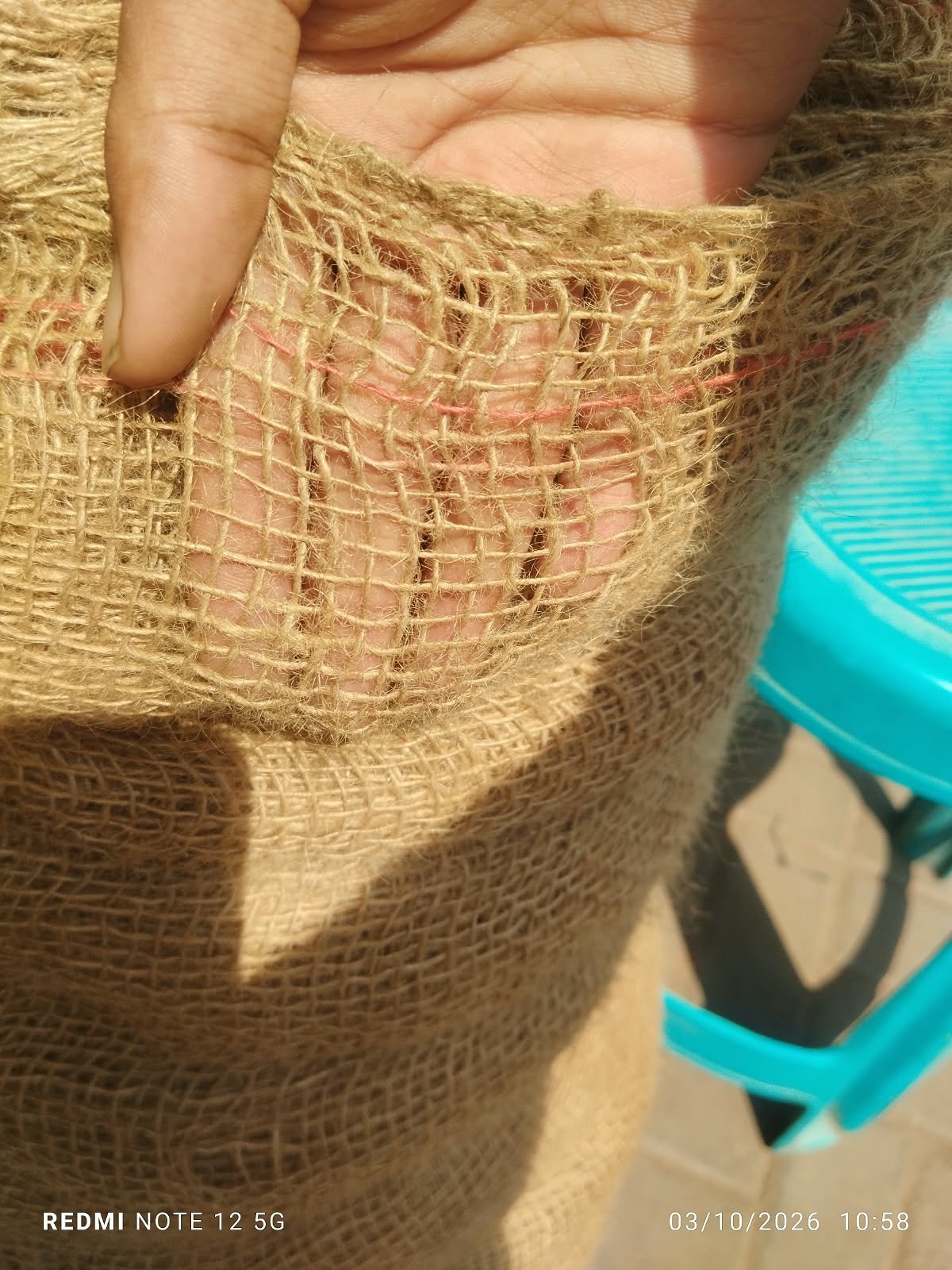
To overcome this limitation, I searched for a more suitable material in the offline market and purchased a jute-based mesh material. The new mesh had much smaller and more uniform openings of approximately 0.5 cm (5 mm). Compared with the previously available material, this mesh was better suited for the cooling chamber because it provided a larger effective surface area for water absorption while still allowing air to pass through.
The selected jute mesh is now being prepared for installation on the cooling chamber.
4/10
Preparation of the Jute mesh and Aluminum Pipe Assembly
Before starting the fabrication of the cooling chamber structure, I worked on preparing the mesh assembly. The selected jute mesh was attached to the aluminum pipes to create a water-absorbing surface for the evaporative cooling system. The arrangement was designed to allow water to spread through the mesh and flow downward under gravity.
After completing the initial mesh and aluminum pipe assembly, I started fabricating the supporting structure required to install it in the BSF cooling chamber. The required rods were cut to the appropriate dimensions to prepare the frame and provide proper support for the mesh assembly.

Fabrication of the Chamber Structure
The next stage of the Black Soldier Fly (BSF) cooling chamber project involved preparing the supporting structure required to hold the mesh material and facilitate water circulation. Initially, the required rods were cut to the appropriate dimensions for fabricating the chamber frame and supporting the mesh.
After cutting the rods, welding was planned to assemble the structure. However, due to electricity supply issues, the welding work had to be postponed. The assembly was completed the following morning. Later that night, the unwanted and extra portions of the material were removed to achieve the required dimensions.
Due to continued electricity interruptions, the fabrication process progressed slowly. During the initial assembly, the pipes did not align properly, and the structure became unbalanced. To correct this, the components were tightly secured using binding wire. Silicone sealant was then applied over the joints to help prevent water leakage.
the structure was properly positioned and prepared for installation. The aluminum rods supporting the mesh were placed inside the gutter, which serves as the water collection and distribution channel for the cooling system.
Data Logger Setup for Temperature and Humidity Monitoring
To evaluate the performance of the cooling chamber, a data logger was planned to monitor changes in temperature and humidity during operation. The data logger was received the following day, after which preparations were made to connect it to the system.
The objective of this monitoring was to understand the changes occurring inside the chamber and determine whether the system could provide the required cooling and humidity conditions for BSF development.
Initial Water Circulation Trial
During the initial trial, a few important issues were identified in the water distribution system. The mesh did not provide complete coverage as required, and the water supplied by the pump was not flowing through the gutter as expected.
The water was being pumped upward, but its distribution across the gutter was uneven. Instead of spreading uniformly throughout the square-shaped gutter, the water accumulated mainly along one line. The downward flow through the system was also considerably slower than expected.
These observations indicated that the water circulation and distribution arrangements required further modification before the cooling performance could be evaluated properly.
Identification of Possible Causes
One possible reason for the slow water flow was the difference in elevation between the water tank and the gutter. The water tank was positioned at ground level, whereas the gutter was approximately two meters above the ground.
The centrifugal pump being used may not have been able to deliver sufficient water at the required height under the existing operating conditions. Therefore, raising the water tank to a higher position was considered as a possible improvement to reduce the vertical distance the pump needed to overcome. The actual cause, however, still needs to be confirmed through further testing.
Another issue observed during the trial was that the BSF chamber and gutter assembly were slightly tilted. Due to this slope, water accumulated along one side instead of spreading evenly across the entire gutter. This uneven distribution reduced the effectiveness of the water supply arrangement and prevented uniform wetting of the mesh.
Current Status
The supporting structure has been assembled, the aluminum rods and mesh arrangement have been positioned, and the initial water circulation trial has been conducted. However, the system is not yet operating as intended because of insufficient upward water delivery, uneven water distribution in the gutter, and incomplete mesh coverage.
The next phase will focus on correcting these issues and establishing uniform water flow over the wetting surface. Once the water circulation system is functioning properly, temperature and humidity data will be collected to evaluate the effectiveness of evaporative cooling and determine the chamber’s suitability for maintaining favorable environmental conditions for BSF development.