Introduction
In this assignment, I learned about different output devices and how to interface them with the XIAO RP2040 microcontroller. Output devices help a system communicate information by producing visible or physical outputs. They are important in electronics because they convert signals from the microcontroller into useful actions.
During this work, I used different output devices to understand their working and control methods. I used a 16×2 LED display to show text and numbers. I also used an OLED display to display text and graphics clearly. The 8×8 LED matrix was used to create simple patterns, letters, and animations, which helped me understand matrix control. I used an SG90 servo motor to learn how a microcontroller can control movement and position. I also experimented with an RGB LED to create different colors and toy motor to understand basic motor control.
Through this assignment, I learned how to connect and program different output devices with the XIAO RP2040. I gained practical knowledge about circuit connections, coding, and troubleshooting. This experience improved my understanding of microcontrollers and the use of output devices in real-life electronic projects.

Individual assignment
Task:
For the individual assignment, I connected different output devices to a microcontroller and programmed them to test their functionality.
Group assignment
Task:
Calculate the power consumption of the output device.
Output Devices:
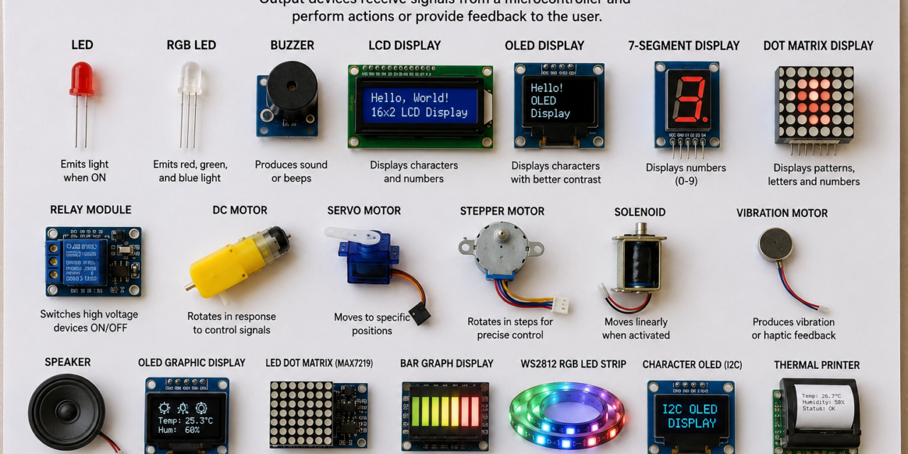
Output devices are hardware components that receive processed data from a computer or microcontroller and present it in a form that users or other systems can understand. They convert digital signals into physical outputs such as light, sound, movement, or displayed information.
These devices play an important role in electronic and embedded systems by providing feedback, displaying results, or controlling external components. Depending on the application, output devices can produce visual, auditory, or mechanical outputs that help users monitor and interact with the system.
Some common examples of output devices include LEDs, LCD displays, seven-segment displays, speakers, buzzers, motors, and relays. Each device is designed for a specific purpose, making output devices essential in applications such as automation, robotics, smart home systems, and Internet of Things (IoT) projects.
Output devices examples:

Components I used for my board are as follows:-
LED(Light Emitting Diode)
An LED (Light Emitting Diode) is a semiconductor device that produces light when electric current passes through it. It converts electrical energy into light energy and is known for its low power consumption, small size, and long working life. An LED has two terminals: the anode (positive terminal) and the cathode (negative terminal).
Pin Description

- Anode (+): The longer lead of the LED, connected to the positive power supply.
- Cathode (-): The shorter lead of the LED, connected to the ground or negative supply.
Internal Structure

An LED consists of a semiconductor chip, epoxy lens, reflector, and metal leads. The semiconductor chip contains a PN junction where light is generated when current flows through it. The epoxy lens protects the internal parts and helps focus the emitted light. The reflector and lead frame support the chip and improve light efficiency.
Applications
- LEDs are used as indicator lights in electronic devices to show power status and operating conditions.
- They are used in display panels, digital screens, and signboards for clear visual information.
- They are widely used in home, industrial, and automotive lighting systems due to their efficiency.
- They are used in smart devices and energy-saving lighting applications because of their low power consumption and long lifespan.
Developed System

Here is the code I used:-
const int ledPin = D10;

void setup() {
  pinMode(ledPin, OUTPUT);
}

void loop() {
  digitalWrite(ledPin, HIGH);  // LED ON
  delay(1000);                 // Wait 1 second

  digitalWrite(ledPin, LOW);   // LED OFF
  delay(1000);                 // Wait 1 second
}
Servo motor SG90
The SG90 servo motor is a small and lightweight motor used for precise position control in electronic and robotic applications. It converts electrical signals into controlled mechanical movement and can rotate its shaft to a specific angle. Due to its compact size, low cost, and easy control, it is commonly used with Arduino and other microcontroller-based projects.
Pin Description

- VCC (+): Provides power supply to the servo motor, usually 5V.
- GND (-): Connects the motor to the ground of the circuit.
- Signal: Receives control signals from the microcontroller to set the motor position.
Internal Structure

The SG90 servo motor contains a small DC motor, gear system, control circuit, and output shaft. The DC motor generates rotation, while the gears reduce speed and increase torque for accurate movement. The control circuit processes input signals and adjusts the motor position. The outer plastic casing protects the internal components and provides a compact design.

Applications
- Used in robotic arms and small robotic projects.
- Used in RC cars, airplanes, and model vehicles.
- Used for controlling the position of sensors and mechanical parts.
- Used in Arduino and microcontroller-based automation projects.
Developed System


Here is the code I used:-
#include <Servo.h>

Servo sg90;

void setup() {
  Serial.begin(115200);
  sg90.attach(D2);

  sg90.write(90);   // Start at center

  Serial.println("=== SG90 Servo Control ===");
  Serial.println("Enter an angle (0-180) and press Enter.");
}

void loop() {
  if (Serial.available() > 0) {
    int angle = Serial.parseInt();

    if (angle >= 0 && angle <= 180) {
      sg90.write(angle);

      Serial.print("Servo moved to: ");
      Serial.print(angle);
      Serial.println(" degrees");
    } else {
      Serial.println("Please enter a value between 0 and 180.");
    }

    while (Serial.available()) {
      Serial.read();
    }
  }
}
OLED display
The 0.91-inch 128×32 Blue OLED display with I2C/IIC interface is a compact display module used to show text, numbers, symbols, and simple graphics in electronic projects. It uses OLED technology, where each pixel produces its own light, providing clear output, high contrast, and low power consumption. It is commonly used with microcontrollers such as Arduino, ESP32, and other embedded systems.
Pin Description

- VCC: Provides power supply to the OLED display module.
- GND: Connects the display to the ground of the circuit.
- SDA: Transfers data between the display and microcontroller.
- SCL: Provides clock signals for I2C communication.
Internal Structure

The OLED display consists of an OLED panel, driver IC, PCB, and connection pins. The OLED panel contains a 128×32 pixel grid where each pixel produces light when powered. The driver IC controls the pixels and processes data received from the microcontroller. The PCB connects all internal components and provides external connections.
Applications
- Used in small electronic devices for displaying information.
- Used in sensor monitoring and measurement systems.
- Used in wearable devices and portable electronics.
- Used in Arduino, ESP32, and other embedded projects.
Developed System


Here is the code I used:-
#include <Wire.h>
#include <Adafruit_GFX.h>
#include <Adafruit_SSD1306.h>

#define SCREEN_WIDTH 128
#define SCREEN_HEIGHT 32
#define OLED_RESET -1

Adafruit_SSD1306 display(SCREEN_WIDTH, SCREEN_HEIGHT, &Wire, OLED_RESET);

void setup() {
  Serial.begin(115200);

  Wire.setSDA(D4);
  Wire.setSCL(D5);
  Wire.begin();

  if (!display.begin(SSD1306_SWITCHCAPVCC, 0x3C)) {
    Serial.println("OLED not found");
    while (1);
  }

  display.clearDisplay();
  display.setTextSize(2);
  display.setTextColor(SSD1306_WHITE);
  display.setCursor(0, 0);
  display.println("Atharv");
  display.display();
}

void loop() {
}
MAX7219 LED Matrix
The MAX7219 LED Matrix is a compact display module used to show text, numbers, symbols, and simple graphics in electronic projects. It contains an 8×8 LED matrix with 64 LEDs controlled by the MAX7219 driver IC. The module is easy to interface with microcontrollers like Arduino and ESP32 due to its simple communication method and low number of connections.
Pin Description

- VCC: Provides power supply to the LED matrix module.
- GND: Connects the module to the ground of the circuit.
- DIN: Receives display data from the microcontroller.
- CLK: Provides clock signals for data communication.
- CS: Controls communication between the microcontroller and the MAX7219 driver.
Internal Structure

The MAX7219 LED Matrix consists of an 8×8 LED array, MAX7219 driver IC, and PCB. The LED array contains 64 LEDs arranged in rows and columns to create different patterns and characters. The driver IC controls LED switching, brightness, and data processing. The PCB connects all components and provides external interface pins.
Applications
- Used in digital clocks, counters, and timers.
- Used in scrolling text displays and message boards.
- Used in robotics, IoT, and automation projects.
- Used with Arduino, ESP32, and other microcontroller-based systems.
Developed System


Here is the code I used:-
#include <MD_MAX72xx.h>
#include <SPI.h>

#define HARDWARE_TYPE MD_MAX72XX::FC16_HW
#define MAX_DEVICES 1

#define DATA_PIN D10
#define CLK_PIN  D8
#define CS_PIN   D9

MD_MAX72XX mx = MD_MAX72XX(HARDWARE_TYPE, DATA_PIN, CLK_PIN, CS_PIN, MAX_DEVICES);

const uint8_t heart[8] = {
  B01100110,
  B11111111,
  B11111111,
  B11111111,
  B01111110,
  B00111100,
  B00011000,
  B00000000
};

void setup() {
  mx.begin();
  mx.control(MD_MAX72XX::INTENSITY, 5);
  mx.clear();

  for (uint8_t row = 0; row < 8; row++) {
    for (uint8_t col = 0; col < 8; col++) {
      bool pixel = bitRead(heart[row], 7 - col);
      mx.setPoint(row, col, pixel);
    }
  }

  mx.update();
}

void loop() {
  // Heart remains displayed
}
LCD Display
The 16×2 Green LCD display with a 4-pin I2C interface is a display module used to show text, numbers, and symbols in electronic projects. It has 16 columns and 2 rows, allowing it to display up to 32 characters. The I2C interface reduces wiring by allowing the LCD to communicate with a microcontroller using only four connections.
Pin Description

- VCC: Provides power supply to the LCD module, usually 5V.
- GND: Connects the LCD module to the ground of the circuit.
- SDA: Transfers data between the LCD and the microcontroller.
- SCL: Provides clock signals for I2C communication.
Internal Structure

The 16×2 LCD consists of a liquid crystal display panel, controller IC, I2C adapter module, and backlight. The LCD panel contains a 16×2 character grid for displaying information. The controller IC manages character display, while the I2C adapter converts serial data into signals required by the LCD. The green backlight improves visibility in different lighting conditions.
Applications
- Used in Arduino and microcontroller-based projects.
- Used for displaying sensor readings and system information.
- Used in digital meters and electronic devices.
- Used in automation systems and control panels.
Developed System


Here is the code I used:-
#include <Wire.h>
#include <LiquidCrystal_I2C.h>

LiquidCrystal_I2C lcd(0x27, 16, 2);   // Change to 0x3F if your LCD uses that address

void setup() {
  Wire.setSDA(D4);
  Wire.setSCL(D5);
  Wire.begin();

  lcd.init();
  lcd.backlight();

  // Display "Atharv" in the center of the first line
  lcd.setCursor(5, 0);
  lcd.print("Atharv");
}

void loop() {
  // Nothing to do
}
Buzzer
A buzzer is an electronic sound-producing device used to generate audio signals or alerts. It converts electrical energy into sound energy using electromagnetic or piezoelectric principles. Buzzers are commonly used in electronic circuits for alarms, notifications, and warning systems.
Pin Description

- Positive (+): Connects to the positive power supply.
- Negative (-): Connects to the ground terminal of the circuit.
Internal Structure

A buzzer consists of a sound-producing element, coil or piezoelectric material, diaphragm, and protective casing. In an electromagnetic buzzer, the coil creates a magnetic field that causes the diaphragm to vibrate and produce sound. The outer casing protects the internal components and helps improve sound output.
Applications
- Used in alarm systems and warning devices.
- Used in electronic gadgets for notification sounds.
- Used in Arduino and microcontroller-based projects.
- Used in security systems and automation applications.
Developed System

Here is the code I used:-
#define BUZZER_PIN 0

void setup() {
  pinMode(BUZZER_PIN, OUTPUT);
}

void loop() {
  digitalWrite(BUZZER_PIN, HIGH);  // ON
  delay(500);
  digitalWrite(BUZZER_PIN, LOW);   // OFF
  delay(500);
}
RGB LED
An RGB LED (Red, Green, Blue LED) is a type of LED that can produce multiple colors by combining red, green, and blue light. It contains three individual LED elements inside a single package, which allows it to create different color combinations. RGB LEDs are widely used in lighting systems, displays, and electronic projects.
Pin Description

- R (Red): Controls the red color output of the LED.
- G (Green): Controls the green color output of the LED.
- B (Blue): Controls the blue color output of the LED.
- Common Pin: Connected to power supply in common anode type or ground in common cathode type.
Internal Structure

An RGB LED contains three separate semiconductor chips for red, green, and blue light generation. These LED chips are placed inside a single transparent package and connected to individual control pins. By changing the brightness of each color using different current levels, various colors can be produced. The epoxy lens protects the internal components and helps spread the light evenly.
Applications
- Used in decorative lighting and LED strips.
- Used in display panels and indicator systems.
- Used in smart lighting and IoT applications.
- Used in robotics and Arduino-based color control projects.
Developed System


Here is the code I used:-
#define RED_PIN    0   // D0
#define GREEN_PIN  1   // D1
#define BLUE_PIN   2   // D2

void setup() {
  pinMode(RED_PIN, OUTPUT);
  pinMode(GREEN_PIN, OUTPUT);
  pinMode(BLUE_PIN, OUTPUT);
}

void setColor(bool r, bool g, bool b) {
  digitalWrite(RED_PIN, r);
  digitalWrite(GREEN_PIN, g);
  digitalWrite(BLUE_PIN, b);
}

void loop() {
  // Red
  setColor(HIGH, LOW, LOW);
  delay(1000);

  // Green
  setColor(LOW, HIGH, LOW);
  delay(1000);

  // Blue
  setColor(LOW, LOW, HIGH);
  delay(1000);

  // Yellow
  setColor(HIGH, HIGH, LOW);
  delay(1000);

  // Cyan
  setColor(LOW, HIGH, HIGH);
  delay(1000);

  // Magenta
  setColor(HIGH, LOW, HIGH);
  delay(1000);

  // White
  setColor(HIGH, HIGH, HIGH);
  delay(1000);

  // Off
  setColor(LOW, LOW, LOW);
  delay(1000);
}
Relay Module
A relay module is an electronic switching device used to control high-voltage or high-current devices with a low-voltage control signal. It works as an electrically operated switch that allows a microcontroller like Arduino or ESP32 to control external devices safely. Relay modules are commonly used in automation and control systems.
Pin Description

- VCC: Provides power supply to the relay module.
- GND: Connects the module to the ground of the circuit.
- IN (Signal): Receives control signals from the microcontroller to switch the relay ON or OFF.
Internal Structure

A relay module consists of an electromagnetic relay, driver circuit, transistor, diode, indicator LED, and terminal connectors. The electromagnetic coil creates a magnetic field when current flows through it, moving the internal switch contacts. The driver circuit controls the relay operation and protects the controlling device from voltage spikes.
Applications
- Used for controlling lights, fans, and electrical appliances.
- Used in home automation systems.
- Used in industrial control and switching applications.
- Used with Arduino, ESP32, and other microcontroller projects.
Developed System

Here is the code I used:-
#define RELAY_PIN 0

void setup() {
  pinMode(RELAY_PIN, OUTPUT);

  // OFF at startup (change to HIGH if your relay is active LOW)
  digitalWrite(RELAY_PIN, LOW);
}

void loop() {
  // Relay ON
  digitalWrite(RELAY_PIN, HIGH);
  delay(1000);

  // Relay OFF
  digitalWrite(RELAY_PIN, LOW);
  delay(1000);
}
Group Assignment
Objective of the Group Assignment
Measure the power consumption of an output device
In this assignment, we learned about output devices used in electronic components. As a group, we studied different output devices such as an LED, an OLED display, and a BO motor. We tested how device works and measured its power consumption. This activity helped us understand the operation of these devices and compare the electrical power required by each one.

1) First, we measured the voltage and current of the BO motor to determine its power consumption.
We used a BO motor in this experiment to measure its power consumption. The motor was connected to our ESP32C3 board . A simple Arduino IDE program was uploaded to make the BO motor rotate continuously. While the motor was running, we measured the voltage across the motor and the current flowing through it to calculate its electrical power consumption.


- Voltage (V) = 7.03 V
- Current (I) = 0.149 A
To calculate the power consumption:Power Consumption = 1.05 W (approximately)
2) Next we calculated the power consumption stepper motor.
Next, we measured the voltage across the stepper motor and the current it consumed during operation. The measured values were then used to calculate the power consumption of the stepper motor using the equation P = V × I.


- Voltage (V) = 12.06 V
- Current (I) = 0.173 A
Using the power formula:
P=V×I
P=12.06×0.173
P=2.08638 W
Power Consumption = 2.09 W