Introduction
During this week, I explored the fundamentals of input devices and their importance in embedded systems. The learning process began with understanding what input devices are, how they work, and how they collect information from the surrounding environment. I studied the internal structure and working principles of various sensors to understand the components and mechanisms responsible for their operation. Additionally, I referred to sensor datasheets to learn about their specifications, pin configurations, operating voltages, and output characteristics.
After understanding the theoretical concepts, I performed practical experiments using different sensors and Arduino. The sensors were connected to the microcontroller, programmed, and tested by observing their outputs through the Serial Monitor. This helped me understand how sensor data is generated and processed in real-world applications.
During the practical sessions, I also learned the difference between analog and digital signals. The outputs of various sensors were analyzed using an oscilloscope to observe their signal behavior and gain a deeper understanding of sensor communication and data acquisition.
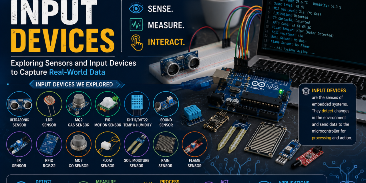
The sensors explored during this week included DHT11 and DHT22 temperature and humidity sensors, Sound Sensor, IR Sensor, PIR Sensor, Ultrasonic Sensor, RFID Sensor, MQ2 Gas Sensor, MQ7 Carbon Monoxide Sensor, Float Sensor, LDR (Light Dependent Resistor), Soil Moisture Sensor, Rain Sensor, and Flame Sensor. Through both theoretical study and hands-on experimentation, I gained valuable knowledge about sensor technologies and their applications in embedded and IoT systems.
What are Input Devices?
Input devices are electronic components that collect information from the surrounding environment and provide it to a processing unit such as a microcontroller or computer. They act as the sensing elements of an embedded system, enabling it to detect changes in physical conditions and respond accordingly.
These devices can measure various environmental parameters such as temperature, humidity, light intensity, motion, distance, sound, gas concentration, water level, and many others. The data collected by input devices is converted into electrical signals that can be processed by the microcontroller to make decisions or trigger specific actions.
Input devices play a crucial role in automation, robotics, Internet of Things (IoT), and smart systems because they allow machines to interact with the real world. Without input devices, a system would not be able to sense its surroundings or gather the information required for operation.
Some common examples of input devices include temperature sensors, humidity sensors, PIR motion sensors, ultrasonic sensors, gas sensors, light sensors, RFID modules, soil moisture sensors, and rain sensors. Throughout this week, various input devices were studied to understand their working principles, internal structures, output signals, and practical applications in embedded systems.

What is a Sensor?
A sensor is an electronic device that detects changes in the surrounding environment and converts them into electrical signals that can be processed by a microcontroller or computer. Sensors act as the sensing elements of an embedded system, allowing it to gather information from the physical world.
Different sensors are designed to detect different types of physical parameters such as temperature, humidity, light intensity, sound, motion, distance, gas concentration, water level, and pressure. When a change is detected, the sensor generates an output signal that represents the measured value.
Sensors are widely used in automation systems, robotics, industrial monitoring, smart homes, healthcare devices, and Internet of Things (IoT) applications. They help machines interact with their surroundings and make decisions based on real-time data.
In this week’s assignment, various sensors were studied and tested to understand their working principles, output signals, applications, and methods of interfacing with Arduino. This practical experience helped in understanding how sensors serve as the primary source of information in embedded systems.

How Sensors Work
Sensor works by detecting a physical change in the environment and converting it into an electrical signal. These physical changes can include temperature, light intensity, motion, sound, distance, humidity, gas concentration, or water level. Once the sensor detects a change, it generates an output signal that is sent to a microcontroller for processing. The microcontroller analyzes the received data and performs the required action based on the programmed instructions.
For example, an LDR sensor detects changes in light intensity, a PIR sensor detects motion, and a gas sensor detects the presence of gases in the surrounding environment. Although different sensors detect different physical quantities, their basic working principle remains the same: sensing a physical parameter, converting it into an electrical signal, and transmitting that signal to a processing unit.

Sensors Explored During This Week
During this week, a variety of input sensors were introduced to understand how different physical parameters can be detected and processed in embedded systems. We studied the working principle, internal structure, datasheets, and applications of each sensor. Some of these sensors were also practically interfaced with Arduino, while others were studied to understand their functionality and real-world use cases.
The following sensors were explored during this week:
1. DHT11 Temperature and Humidity Sensor
The DHT11 is a digital sensor used to measure temperature and humidity. It is commonly used in weather stations, home automation, and environmental monitoring projects.

DHT11 Sensor
2. DHT22 Temperature and Humidity Sensor
The DHT22 is an advanced version of the DHT11, offering higher accuracy and a wider measurement range. It is suitable for applications requiring precise environmental monitoring.

DHT22 Sensor
3. Sound Sensor
A Sound Sensor detects sound waves using a built-in microphone and converts them into electrical signals. It is commonly used in clap switches, sound monitoring, and security systems.

Sound Sensor
4. IR (Infrared) Sensor
An IR Sensor detects nearby objects using infrared light. It consists of an IR transmitter and receiver and is widely used in obstacle detection, object sensing, and automation projects.

IR Sensor
5. PIR Motion Sensor
A PIR Sensor detects human or animal movement by sensing changes in infrared radiation. It is commonly used in security systems and automatic lighting.

PIR Sensor
6. Ultrasonic Sensor
The Ultrasonic Sensor measures the distance between the sensor and an object using ultrasonic sound waves. It is widely used in obstacle detection and distance measurement applications.

Ultrasonic Sensor
7. RFID RC522 Module
The RFID RC522 module reads RFID cards and tags using radio frequency communication. It is commonly used in attendance systems and access control applications.

RFID RC522 Module
8. MQ2 Gas Sensor
The MQ2 Sensor detects combustible gases and smoke in the surrounding environment. It is commonly used in gas leakage detection and fire safety systems.

MQ2 Gas Sensor
9. MQ7 Carbon Monoxide Sensor
The MQ7 Sensor is specifically designed to detect Carbon Monoxide (CO) gas. It is widely used in air quality monitoring and industrial safety applications.

MQ7 Sensor
10. LDR (Light Dependent Resistor)
An LDR is a light-sensitive sensor whose resistance changes according to the intensity of light falling on its surface. It is commonly used in automatic lighting systems and light-controlled devices.

LDR Sensor
11. Soil Moisture Sensor
The Soil Moisture Sensor measures the moisture content present in soil. It is widely used in smart irrigation and agricultural monitoring systems.

Soil Moisture Sensor
12. Rain Sensor
The Rain Sensor detects the presence of water or rainfall by sensing changes in conductivity on its detection plate. It is commonly used in weather monitoring systems.

Rain Sensor
13. Flame Sensor
The Flame Sensor detects fire by sensing infrared radiation emitted by flames. It is commonly used in fire detection and safety systems.

Flame Sensor
14. Float Sensor
The Float Sensor detects the level of water or other liquids using a floating mechanism. It is commonly used in water tanks and automatic level control systems.

Float Sensor
Individual Assignment
During this week’s individual assignment, I performed hands-on interfacing of different input sensors with an Arduino Uno and XIAO ESP32-C3 to understand their working principles and practical applications. Each sensor was connected according to its circuit diagram, programmed using the Arduino IDE, and tested to verify its functionality. Depending on the sensor, the output was observed through the Serial Monitor or by controlling output devices such as LEDs and buzzers.
This practical exercise helped me understand how different input devices communicate with a microcontroller, how sensor data is processed, and how appropriate actions can be performed based on the received input signals.
The following sensors were successfully interfaced and tested during this assignment:
- DHT11 Temperature and Humidity Sensor
- DHT22 Temperature and Humidity Sensor
- Sound Sensor
- PIR Motion Sensor
- Ultrasonic Sensor
- RFID RC522 Module
- MQ2 Gas Sensor
- Float Sensor
Sensors Used with Arduino Uno
1. DHT11 Temperature and Humidity Sensor
The DHT11 is a digital sensor used to measure temperature and humidity from the surrounding environment. It is one of the most commonly used sensors in beginner electronics and IoT projects due to its simple interface and reliable performance.
The sensor contains a humidity sensing element and a temperature sensing element. It processes the measured values internally and sends the data digitally to the microcontroller.
Practical Activity
In this activity, the DHT11 sensor was connected to an Arduino board and programmed using the appropriate library. After uploading the code, the temperature and humidity values were displayed on the Serial Monitor. By observing these readings, I learned how environmental data can be collected and monitored in real time using a digital sensor.


Code used For DHT 11
#include <DHT.h>#define DHTPIN 2#define DHTTYPE DHT11DHT dht(DHTPIN, DHTTYPE);void setup() { Serial.begin(9600); dht.begin();}void loop() { float humidity = dht.readHumidity(); float temperature = dht.readTemperature(); Serial.print("Humidity: "); Serial.print(humidity); Serial.print("% "); Serial.print("Temperature: "); Serial.print(temperature); Serial.println("°C"); delay(2000);}Observation
The DHT11 sensor successfully measured the surrounding temperature and humidity and continuously transmitted the data to Arduino. The values were displayed on the Serial Monitor, demonstrating real-time environmental monitoring.
2. DHT22 Temperature and Humidity Sensor
The DHT22 is a digital temperature and humidity sensor that provides higher accuracy and a wider measurement range compared to the DHT11. It is commonly used in weather stations, environmental monitoring systems, and IoT applications where more precise readings are required.
The sensor measures the surrounding temperature and humidity and transmits the data digitally to the microcontroller. Due to its improved accuracy, it is often preferred for projects that require reliable environmental data.
Practical Activity
In this activity, the DHT22 sensor was interfaced with Arduino and tested using a sample program. After uploading the code, the temperature and humidity readings were observed through the Serial Monitor. The sensor continuously provided real-time environmental data, allowing comparison with the DHT11 sensor.


Code used For DHT 22
#include <DHT.h>#define DHTPIN 2 // DHT22 Data Pin connected to Arduino Pin 2#define DHTTYPE DHT22 // Define Sensor TypeDHT dht(DHTPIN, DHTTYPE);void setup() { Serial.begin(9600); Serial.println("DHT22 Sensor Test"); dht.begin();}void loop() { float humidity = dht.readHumidity(); float temperature = dht.readTemperature(); if (isnan(humidity) || isnan(temperature)) { Serial.println("Failed to read from DHT22 sensor!"); return; } Serial.print("Temperature: "); Serial.print(temperature); Serial.print(" °C\t"); Serial.print("Humidity: "); Serial.print(humidity); Serial.println(" %"); delay(2000);}Observation
The DHT22 sensor successfully measured temperature and humidity values and displayed them on the Serial Monitor. Compared to the DHT11, it provided a wider measurement range and more accurate readings, making it suitable for advanced monitoring applications.
3. Sound Sensor
A sound sensor is an electronic device used to detect sound waves and measure sound intensity in the surrounding environment. It contains a microphone that converts sound vibrations into electrical signals, allowing a microcontroller to respond to sound-based events.
Practical Activity
In this activity, the sound sensor was connected to Arduino along with a buzzer. The sensor was programmed to detect clap sounds. Whenever a clap was detected near the sensor, the Arduino triggered the buzzer, producing an audible alert. This experiment demonstrated how sound can be used as an input signal to control electronic devices.


Code used For Sound Sensor
int soundPin = 2;int buzzerPin = 8;void setup() { pinMode(soundPin, INPUT); pinMode(buzzerPin, OUTPUT);}void loop() { if (digitalRead(soundPin) == HIGH) { digitalWrite(buzzerPin, HIGH); delay(1000); digitalWrite(buzzerPin, LOW); }}Observation
The sound sensor successfully detected clap sounds and triggered the buzzer whenever a sound above the threshold level was detected. This activity demonstrated how sound can be used as an input to activate an output device in an embedded system.
4. PIR Sensor (Passive Infrared Sensor)
A PIR (Passive Infrared) Sensor is used to detect motion by sensing changes in infrared radiation emitted by humans and animals. It is commonly used in security systems, automatic lighting, and motion detection applications.
The sensor continuously monitors infrared energy in its surroundings. When a person or object moves within its detection range, the sensor detects the change and generates an output signal.
Practical Activity
In this activity, the PIR sensor was connected to Arduino along with an LED. The sensor was programmed so that whenever motion was detected, the LED turned ON automatically. When no motion was present, the LED remained OFF. This experiment demonstrated how motion can be used as an input signal to control an output device


Code used For PIR Sensor
int pirPin = 2;int ledPin = 13;void setup() { pinMode(pirPin, INPUT); pinMode(ledPin, OUTPUT); Serial.begin(9600);}void loop() { int motion = digitalRead(pirPin); if (motion == HIGH) { digitalWrite(ledPin, HIGH); Serial.println("Motion Detected"); } else { digitalWrite(ledPin, LOW); Serial.println("No Motion"); } delay(500);}Observation
When motion was detected in front of the PIR sensor, the LED turned ON and the message “Motion Detected” was displayed on the Serial Monitor. When no motion was present, the LED remained OFF and “No Motion” was displayed. This demonstrated how motion sensing can be used to trigger actions in embedded systems.
5. Ultrasonic Sensor (HC-SR04)
The Ultrasonic Sensor is used to measure the distance between the sensor and an object. It works by transmitting ultrasonic sound waves and measuring the time taken for the reflected waves to return to the sensor.
The sensor consists of a transmitter and a receiver. The transmitter emits ultrasonic pulses, and the receiver detects the reflected signal. Based on the travel time of the sound wave, the distance is calculated.
Practical Activity
In this activity, the Ultrasonic Sensor was connected to Arduino and tested for distance measurement. Objects were placed at different distances from the sensor, and the measured distance values were displayed on the Serial Monitor. By moving the object closer and farther away, changes in the distance readings could be observed in real time.


Code used For Ultrasonic Sensor
#define trigPin 9#define echoPin 10void setup() { Serial.begin(9600); pinMode(trigPin, OUTPUT); pinMode(echoPin, INPUT);}void loop() { long duration; int distance; digitalWrite(trigPin, LOW); delayMicroseconds(2); digitalWrite(trigPin, HIGH); delayMicroseconds(10); digitalWrite(trigPin, LOW); duration = pulseIn(echoPin, HIGH); distance = duration * 0.034 / 2; Serial.print("Distance: "); Serial.print(distance); Serial.println(" cm"); delay(500);}Observation
The Ultrasonic Sensor successfully measured the distance of nearby objects and displayed the readings on the Serial Monitor. The values changed according to the position of the object, demonstrating real-time distance measurement using ultrasonic waves.
6. RFID RC522 Module
The RFID (Radio Frequency Identification) RC522 module is used for wireless identification and access control applications. It communicates with RFID cards or tags using radio frequency signals and retrieves the unique identification number (UID) stored in the card.
RFID technology is widely used in attendance systems, access control systems, inventory tracking, and smart identification applications.
Practical Activity
In this activity, the RFID RC522 module was connected to Arduino along with a buzzer. When an RFID card was scanned near the reader, the module detected the card and transmitted its UID to the Arduino. The UID was displayed on the Serial Monitor, and the buzzer was activated for one second to indicate a successful card scan.


Code used For RFID Sensor
#include <SPI.h>#include <MFRC522.h>#define SS_PIN 10#define RST_PIN 9#define BUZZER 8MFRC522 rfid(SS_PIN, RST_PIN);void setup() { Serial.begin(9600); SPI.begin(); rfid.PCD_Init(); pinMode(BUZZER, OUTPUT); Serial.println("Scan RFID Card");}void loop() { if (!rfid.PICC_IsNewCardPresent()) return; if (!rfid.PICC_ReadCardSerial()) return; Serial.print("UID: "); for (byte i = 0; i < rfid.uid.size; i++) { Serial.print(rfid.uid.uidByte[i], HEX); Serial.print(" "); } Serial.println(); digitalWrite(BUZZER, HIGH); delay(1000); digitalWrite(BUZZER, LOW); rfid.PICC_HaltA();}Observation
The RFID RC522 module successfully detected RFID cards and displayed their unique identification numbers (UIDs) on the Serial Monitor. Whenever a card was scanned, the buzzer sounded for one second, providing an audible indication that the card had been successfully read. This demonstrated a simple RFID-based identification system.
7. MQ2 Gas Sensor
The MQ2 is a gas sensor used to detect smoke, LPG, methane, propane, and other combustible gases in the surrounding environment. It is commonly used in gas leakage detection systems, fire safety applications, and air quality monitoring projects.
The sensor contains a sensitive material whose resistance changes when exposed to gases. These changes are converted into electrical signals that can be read by a microcontroller.
Practical Activity
In this activity, the MQ2 gas sensor was connected to Arduino and programmed to detect the presence of gas or smoke. When the gas concentration exceeded a predefined threshold, the message “Gas Detected” was displayed on the Serial Monitor. If no gas was detected, the system continued monitoring the environment.


Code used For MQ2 Sensor
int mq2Pin = A0;int threshold = 400;void setup() { Serial.begin(9600);}void loop() { int gasValue = analogRead(mq2Pin); if (gasValue > threshold) { Serial.println("Gas Detected"); } else { Serial.println("No Gas Detected"); } delay(500);}Observation
The MQ2 sensor successfully detected the presence of gas and displayed the message “Gas Detected” on the Serial Monitor whenever the gas concentration exceeded the set threshold. This demonstrated how gas sensors can be used for safety and monitoring applications.
8. Float Sensor (Water Level Sensor)
The Float Sensor is a water level detection sensor used to identify the presence or absence of water at a specific level. It works using a floating mechanism that moves according to the water level and changes the electrical state of the internal switch.
Float sensors are commonly used in water tanks, automatic water level controllers, and liquid monitoring systems.
Practical Activity
In this activity, the Float Sensor was connected to Arduino along with a buzzer for water level indication. When the water level reached a certain point and the float sensor changed its position, the Arduino detected the signal and activated the buzzer as an alert. The sensor status was also monitored through the Serial Monitor.


Code used For float Sensor
int floatPin = 2;int buzzerPin = 8;void setup() { pinMode(floatPin, INPUT_PULLUP); pinMode(buzzerPin, OUTPUT); Serial.begin(9600);}void loop() { int sensorState = digitalRead(floatPin); if (sensorState == LOW) { digitalWrite(buzzerPin, HIGH); Serial.println("Water Level High - Buzzer ON"); } else { digitalWrite(buzzerPin, LOW); Serial.println("Water Level Low - Buzzer OFF"); } delay(500);}Observation
The Float Sensor successfully detected changes in water level and triggered the buzzer when the water reached the set level. The status was also displayed on the Serial Monitor, demonstrating how water level monitoring and alert systems can be implemented using sensors.
Sensors Used with Seeed Studio XIAO ESP32-C3
1. Ultrasonic Sensor
The Ultrasonic Sensor is used to measure the distance between the sensor and an object. It works by transmitting ultrasonic sound waves and measuring the time taken for the reflected waves to return to the sensor. Based on this time, the distance is calculated and displayed.
Practical Activity
In this activity, the Ultrasonic Sensor was interfaced with the Seeed Studio XIAO ESP32-C3. The sensor continuously measured the distance of nearby objects, and the measured values were displayed on the Serial Monitor in real time. By moving an object closer to or farther from the sensor, the distance readings changed accordingly.


Code used For Ultrasonic Sensor
#define TRIG_PIN D2#define ECHO_PIN D3void setup() { Serial.begin(115200); pinMode(TRIG_PIN, OUTPUT); pinMode(ECHO_PIN, INPUT);}void loop() { long duration; float distance; digitalWrite(TRIG_PIN, LOW); delayMicroseconds(2); digitalWrite(TRIG_PIN, HIGH); delayMicroseconds(10); digitalWrite(TRIG_PIN, LOW); duration = pulseIn(ECHO_PIN, HIGH); distance = duration * 0.0343 / 2; Serial.print("Distance: "); Serial.print(distance); Serial.println(" cm"); delay(500);}Observation
The Ultrasonic Sensor was successfully interfaced with the Seeed Studio XIAO ESP32-C3 and accurately measured the distance of nearby objects. The measured values were displayed on the Serial Monitor in real time, demonstrating the XIAO ESP32-C3’s capability to interface with distance sensors for measurement and obstacle detection applications.
2. PIR Motion Sensor
The PIR (Passive Infrared) Sensor is used to detect motion by sensing changes in infrared radiation emitted by humans and animals. It is commonly used in security systems, automatic lighting, and motion detection applications.
The sensor continuously monitors infrared energy in its surroundings. When a person or object moves within its detection range, the sensor detects the change and generates an output signal.
Practical Activity
In this activity, the PIR Motion Sensor was connected to the Seeed Studio XIAO ESP32-C3 along with a buzzer. The sensor was programmed so that whenever motion was detected, the buzzer was activated automatically. At the same time, the message “Motion Detected” was displayed on the Serial Monitor. When no motion was detected, the buzzer remained OFF and the Serial Monitor displayed “No Motion”.


Code used For PIR Sensor
const int pirPin = D2;const int buzzerPin = D3;void setup() { pinMode(pirPin, INPUT); pinMode(buzzerPin, OUTPUT); Serial.begin(115200);}void loop() { int motion = digitalRead(pirPin); if (motion == HIGH) { digitalWrite(buzzerPin, HIGH); Serial.println("Motion Detected"); } else { digitalWrite(buzzerPin, LOW); Serial.println("No Motion"); } delay(500);}Observation
The PIR Motion Sensor successfully detected movement and activated the buzzer whenever motion was present within its detection range. The Serial Monitor displayed “Motion Detected” during motion detection and “No Motion” when no movement was detected. This experiment demonstrated how the Seeed Studio XIAO ESP32-C3 can be used for motion-based alert and security applications.
3.Sound Sensor
The Sound Sensor is used to detect sound waves using a built-in microphone. It converts sound into electrical signals, allowing a microcontroller to respond to events such as claps, loud noises, or voice commands. It is commonly used in sound-activated switches, security systems, and automation projects.
Practical Activity
In this activity, the Sound Sensor was connected to the Seeed Studio XIAO ESP32-C3 along with a buzzer. The sensor was programmed so that whenever a clap or loud sound was detected, the buzzer was activated automatically. At the same time, the message “Sound Detected” was displayed on the Serial Monitor. When no sound was detected, the buzzer remained OFF and the Serial Monitor displayed “No Sound Detected”.


Code used For Sound Sensor
const int soundPin = D2;const int buzzerPin = D3;void setup() { pinMode(soundPin, INPUT); pinMode(buzzerPin, OUTPUT); Serial.begin(115200);}void loop() { int soundState = digitalRead(soundPin); if (soundState == HIGH) { digitalWrite(buzzerPin, HIGH); Serial.println("Sound Detected"); } else { digitalWrite(buzzerPin, LOW); Serial.println("No Sound Detected"); } delay(200);}Observation
The Sound Sensor successfully detected claps and other loud sounds. Whenever a sound was detected, the buzzer was activated and the message “Sound Detected” was displayed on the Serial Monitor. When no sound was present, the buzzer remained OFF and the Serial Monitor displayed “No Sound Detected”. This experiment demonstrated how the Seeed Studio XIAO ESP32-C3 can be used to develop sound-activated alert and automation systems.
4. RFID RC522 Module
The RFID (Radio Frequency Identification) RC522 module is used for wireless identification and access control applications. It communicates with RFID cards or tags using radio frequency signals and reads the unique identification number (UID) stored in the card. RFID technology is widely used in attendance systems, access control, inventory management, and smart identification projects.
Practical Activity
In this activity, the RFID RC522 Module was connected to the Seeed Studio XIAO ESP32-C3 along with a buzzer. The module was programmed to detect RFID cards and tags. Whenever a valid RFID card was brought near the reader, the module successfully read the card’s UID, displayed it on the Serial Monitor, and activated the buzzer for one second to indicate that the card had been scanned successfully.


Code used For RFID Sensor
#include <SPI.h>#include <MFRC522.h>#define SS_PIN D2#define RST_PIN D1#define BUZZER D3MFRC522 rfid(SS_PIN, RST_PIN);void setup() { Serial.begin(115200); SPI.begin(); rfid.PCD_Init(); pinMode(BUZZER, OUTPUT); Serial.println("Scan RFID Card");}void loop() { if (!rfid.PICC_IsNewCardPresent()) return; if (!rfid.PICC_ReadCardSerial()) return; Serial.print("UID: "); for (byte i = 0; i < rfid.uid.size; i++) { Serial.print(rfid.uid.uidByte[i], HEX); Serial.print(" "); } Serial.println(); digitalWrite(BUZZER, HIGH); delay(1000); digitalWrite(BUZZER, LOW); rfid.PICC_HaltA();}Observation
The RFID RC522 Module successfully detected RFID cards and displayed their unique identification numbers (UIDs) on the Serial Monitor. Whenever a card was scanned, the buzzer sounded for one second, providing an audible confirmation that the card had been read successfully. This experiment demonstrated how the Seeed Studio XIAO ESP32-C3 can be used to develop RFID-based attendance, access control, and identification systems.
5. MQ2 Gas Sensor
The MQ2 Gas Sensor is used to detect combustible gases and smoke in the surrounding environment. It is capable of sensing gases such as LPG, methane, propane, hydrogen, and smoke, making it suitable for gas leakage detection and safety applications.
The sensor detects changes in gas concentration and converts them into electrical signals that can be processed by a microcontroller.
Practical Activity
In this activity, the MQ2 Gas Sensor was connected to the Seeed Studio XIAO ESP32-C3 along with a buzzer. The sensor continuously monitored the surrounding environment for the presence of gas or smoke. When the detected gas concentration exceeded the predefined threshold, the buzzer was activated automatically and the message “Gas Detected” was displayed on the Serial Monitor. When no gas was detected, the buzzer remained OFF and the Serial Monitor displayed “No Gas Detected”.


Code used For MQ2 Sensor
const int mq2Pin = 4; // GPIO4const int buzzer = 5; // GPIO5void setup() { pinMode(mq2Pin, INPUT); pinMode(buzzer, OUTPUT); digitalWrite(buzzer, LOW); Serial.begin(115200);}void loop() { int gas = digitalRead(mq2Pin); if (gas == LOW) { Serial.println("Gas Detected"); digitalWrite(buzzer, HIGH); } else { Serial.println("No Gas Detected"); digitalWrite(buzzer, LOW); } delay(500);}Observation
The MQ2 Gas Sensor successfully detected the presence of combustible gases and smoke. Whenever the gas concentration exceeded the predefined threshold, the buzzer was activated and the message “Gas Detected” was displayed on the Serial Monitor. When no gas was detected, the buzzer remained OFF and the Serial Monitor displayed “No Gas Detected”. This experiment demonstrated how the Seeed Studio XIAO ESP32-C3 can be used to develop gas leakage detection and safety monitoring systems.
Float Sensor (Water Level Sensor)
The Float Sensor is a water level detection sensor used to detect the presence or absence of liquid at a specific level. It operates using a floating mechanism that moves with the water level and changes the state of an internal switch. Float sensors are commonly used in water tanks, liquid storage systems, and automatic water level controllers.
Practical Activity
In this activity, the Float Sensor was connected to the Seeed Studio XIAO ESP32-C3 along with a buzzer. The sensor was programmed to monitor the water level continuously. When the water level reached the sensor and the float changed its position, the buzzer was activated automatically and the message “Water Level Detected” was displayed on the Serial Monitor. When the water level was below the sensor, the buzzer remained OFF and the Serial Monitor displayed “Water Level Low”.


Code used For float Sensor
const int floatPin = 4; // GPIO4const int buzzerPin = 5; // GPIO5void setup() { pinMode(floatPin, INPUT_PULLUP); pinMode(buzzerPin, OUTPUT); digitalWrite(buzzerPin, LOW); Serial.begin(115200);}void loop() { int state = digitalRead(floatPin); if (state == LOW) { Serial.println("Water Detected"); digitalWrite(buzzerPin, HIGH); } else { Serial.println("No Water Detected"); digitalWrite(buzzerPin, LOW); } delay(500);}Observation
The Float Sensor was successfully interfaced with the Seeed Studio XIAO ESP32-C3. Whenever the water level reached the sensor, the buzzer was activated and the message “Water Level Detected” was displayed on the Serial Monitor. When the water level dropped below the sensor, the buzzer turned OFF and the Serial Monitor displayed “Water Level Low”. This experiment demonstrated how the XIAO ESP32-C3 can be used for water level monitoring and alert systems.
Analog and Digital Signals
Electronic sensors communicate with microcontrollers by sending electrical signals. These signals are mainly classified into two types: Analog Signals and Digital Signals. Understanding the difference between these signals is essential because different sensors produce different types of outputs, and the microcontroller processes them accordingly.
Analog Signal
An Analog Signal is a continuous signal whose value changes smoothly over time. Unlike digital signals, analog signals are not limited to only two states. Instead, they can have any value within a specific range.
Many sensors, such as LDR, MQ2 Gas Sensor, MQ7 Gas Sensor, Soil Moisture Sensor, Rain Sensor, and Flame Sensor, provide analog outputs that vary depending on environmental conditions. The microcontroller reads these varying voltages using its Analog-to-Digital Converter (ADC) and converts them into digital values for processing.
Characteristics of Analog Signals
- Continuous in nature
- Can have infinite values within a range
- Represents real-world physical quantities
- Processed using the ADC of the microcontroller

Analog Signal Waveform
Digital Signal
A Digital Signal has only two possible states: HIGH (1) and LOW (0). These signals represent binary values and are commonly used by digital sensors to indicate whether a condition is detected or not.
Sensors such as PIR Motion Sensor, RFID Module, Float Sensor, and Sound Sensor (Digital Output) generate digital signals. When a specific condition is detected, the sensor changes its output from LOW to HIGH or vice versa, allowing the microcontroller to perform the required action.
Characteristics of Digital Signals
- Has only two states: HIGH and LOW
- Provides clear ON/OFF output
- Easy to process using digital input pins
- Commonly used in automation and control systems

Digital Signal Waveform
Difference Between Analog and Digital Signals
| Analog Signal | Digital Signal |
|---|---|
| Continuous signal | Discrete signal |
| Has infinite values within a range | Has only two states (HIGH or LOW) |
| Output changes smoothly | Output changes instantly |
| Read using Analog Pins (ADC) | Read using Digital Pins |
| Example: LDR, MQ2, Soil Moisture | Example: PIR, RFID, Float Sensor |
Group Assignment
Introduction
As part of this week’s group assignment, we learned how to use an Oscilloscope for observing and analyzing electrical signals. The main objective of this activity was to understand the working of an oscilloscope and visualize digital signals generated by an electronic circuit. This hands-on session helped us understand how an oscilloscope is used for testing, debugging, and analyzing electronic systems.
What is an Oscilloscope?
An Oscilloscope is an electronic measuring instrument used to display electrical signals as waveforms. It allows us to observe how voltage changes over time, making it easier to analyze the behavior of electronic circuits. Oscilloscopes are widely used in electronics laboratories for testing, troubleshooting, and verifying circuit performance.

Digital Oscilloscope
Practical Activity
During the group assignment, we connected an LED circuit to the oscilloscope to observe its digital output signal. As the LED switched ON and OFF, the oscilloscope displayed the corresponding waveform on its screen. This allowed us to understand how digital signals transition between LOW (0V) and HIGH (Voltage Level).
We also learned how to properly connect the oscilloscope probe to the circuit, select the correct ground connection, and adjust important settings such as the time scale, voltage scale, and trigger controls. These adjustments helped us obtain a stable and clear waveform for accurate observation.

LED Circuit Connected to the Oscilloscope

Observation
The oscilloscope successfully displayed the digital waveform generated by the LED circuit. When the LED turned ON, the waveform changed to the HIGH state, and when the LED turned OFF, the waveform changed to the LOW state. By observing these transitions, we gained a better understanding of digital signal behavior and how electronic signals can be visualized in real time using an oscilloscope.
Conclusion
This group assignment provided valuable hands-on experience in using an oscilloscope to analyze digital signals. It helped us understand the operation of the oscilloscope, waveform visualization, and signal measurement techniques. The knowledge gained during this activity will be useful for testing, debugging, and developing future embedded systems and electronic circuits.
Week Summary
This week focused on understanding Input Devices, Sensors, and Signal Processing in embedded systems. We began by learning what input devices are, how sensors work, and how they convert physical changes from the environment into electrical signals that can be processed by a microcontroller.
During the individual assignments, I explored the internal structure, working principle, and datasheets of various sensors. I practically interfaced multiple sensors with both the Arduino Uno and the Seeed Studio XIAO ESP32-C3. These included the DHT11, DHT22, Sound Sensor, PIR Motion Sensor, Ultrasonic Sensor, RFID RC522 Module, MQ2 Gas Sensor, and Float Sensor. Each sensor was programmed using the Arduino IDE, and its output was observed through the Serial Monitor, LEDs, or Buzzers, depending on the application.
I also learned the difference between Analog and Digital signals and understood how different sensors generate different types of outputs. This knowledge helped me understand how microcontrollers read and process sensor data for real-world applications.
As part of the Group Assignment, we learned how to operate an Oscilloscope and used it to observe the digital waveform generated by an LED circuit. This practical activity helped us visualize signal transitions between HIGH and LOW states and understand how oscilloscopes are used for testing, analyzing, and debugging electronic circuits.
Overall, this week provided valuable hands-on experience in sensor interfacing, signal analysis, and embedded programming. The practical activities improved my understanding of how sensors communicate with microcontrollers and how electronic signals can be measured and analyzed using professional testing equipment. The knowledge gained during this week will be highly useful for developing future IoT and embedded system projects.