Introduction
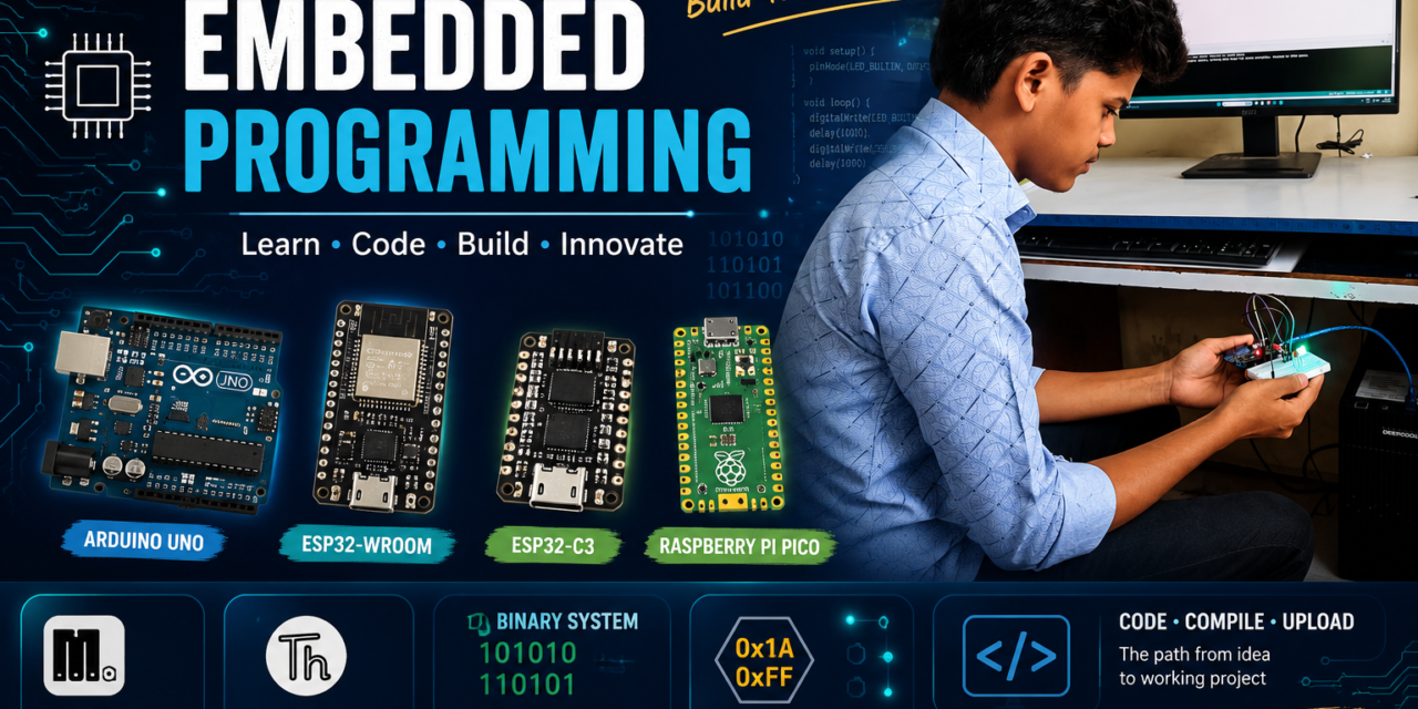
This week, I explored different microcontroller boards such as Arduino Uno, ESP32, ESP32-WROOM, and Raspberry Pi Pico and compared their features and capabilities. I also learned how to install and set up the Thonny IDE for programming. Using the MicroPython language, I wrote and tested simple programs on these boards. In addition, I gained an understanding of binary and hexadecimal number systems, which are important concepts in embedded systems and programming.
Group Assignment
Task:
we studied the datasheets of different microcontroller boards. We compared their basic features, pin details, memory, and specifications. We also learned about the toolchains and development workflows used for different embedded boards. This activity helped us understand how to choose the right board and development process for different projects.
Comparison of Microcontroller
| Parameter | Arduino Uno | ESP32-WROOM | ESP32-C3 | XIAO RP2040 | Raspberry Pi Pico |
|---|---|---|---|---|---|
| Microcontroller | ATmega328P | ESP32 | ESP32-C3 | RP2040 | RP2040 |
| Core | Single Core | Dual Core | Single Core | Dual Core | Dual Core |
| Architecture | 8-bit AVR RISC | 32-bit Xtensa LX6 | 32-bit RISC-V | 32-bit ARM Cortex-M0+ | 32-bit ARM Cortex-M0+ |
| Clock Speed | 16 MHz | Up to 240 MHz | Up to 160 MHz | Up to 133 MHz | Up to 133 MHz |
| Operating Voltage | 5V | 3.3V | 3.3V | 3.3V | 3.3V |
| GPIO Voltage | 5V | 3.3V | 3.3V | 3.3V | 3.3V |
| Digital GPIO Pins | 14 | Up to 34 | Up to 22 | Up to 11 | Up to 26 |
| PWM Pins | 6 | Up to 16 | Up to 6 | Up to 11 | Up to 16 |
| Analog Input Pins | 6 | Up to 18 | Up to 6 | Up to 4 | 3 |
| Communication Protocols | UART, SPI, I2C | UART, SPI, I2C, I2S | UART, SPI, I2C | UART, SPI, I2C | UART, SPI, I2C |
| Wi-Fi | No | Yes | Yes | No | No |
| Bluetooth | No | Yes | Yes (BLE) | No | No |
| Programming Languages | C/C++ | C/C++, MicroPython | C/C++, MicroPython | C/C++, MicroPython | C/C++, MicroPython |
| On-board LED Pin | D13 | GPIO2 | GPIO8 | GPIO25 | GPIO25 |
| Flash Memory | 32 KB | 4 MB | 4 MB | 2 MB | 2 MB |
| RAM | 2 KB SRAM | 520 KB SRAM | 400 KB SRAM | 264 KB SRAM | 264 KB SRAM |
| USB Interface | USB Type-B | Micro-USB | USB Type-C | USB Type-C | Micro-USB |
Development Workflow Comparison
A toolchain is a set of software tools used to write, compile, upload, and debug programs for microcontrollers. In this group assignment, we used Arduino IDE and Thonny IDE to program different microcontroller boards like Arduino UNO, ESP32-WROOM, ESP32-C3 XIAO, and XIAO RP2040. This helped us understand the programming workflow and tools required for different embedded boards.
| Component | Arduino Uno | ESP32-WROOM | ESP32-C3 XIAO | XIAO RP2040 | Raspberry Pi Pico |
|---|---|---|---|---|---|
| Architecture | AVR 8-bit | Xtensa 32-bit | RISC-V 32-bit | ARM Cortex-M0+ 32-bit | ARM Cortex-M0+ 32-bit |
| Programming Language | C/C++ | C/C++, MicroPython | C/C++, MicroPython | C/C++, MicroPython | C/C++, MicroPython |
| IDE (Editor) | Arduino IDE | Arduino IDE, Thonny IDE | Arduino IDE, Thonny IDE | Arduino IDE, Thonny IDE | Arduino IDE, Thonny IDE |
| Compiler | AVR-GCC | Xtensa-ESP32-GCC | RISC-V GCC | ARM GCC (arm-none-eabi-gcc) | ARM GCC (arm-none-eabi-gcc) |
| Uploader Tool | avrdude | esptool | esptool | UF2 Bootloader / bossac | UF2 Bootloader |
| Firmware Support | Arduino Bootloader | ESP32 Firmware, MicroPython Firmware | ESP32-C3 Firmware, MicroPython Firmware | RP2040 Firmware, MicroPython Firmware | RP2040 Firmware, MicroPython Firmware |
| Connection Type | USB Type-B | Micro-USB | USB Type-C | USB Type-C | Micro-USB |
| Execution Method | Compiled and Uploaded | Compiled or Interpreted | Compiled or Interpreted | Compiled or Interpreted | Compiled or Interpreted |
| Debugger Support | Limited | Supported | Supported | Supported | Supported |
| Package Manager | Arduino Library Manager | Arduino Library Manager, ESP-IDF Components | Arduino Library Manager | Arduino Library Manager | Arduino Library Manager |
| Build System | Arduino Build System | Arduino Build System, ESP-IDF | Arduino Build System, ESP-IDF | Arduino Build System | Arduino Build System |
| Bootloader Type | Arduino Bootloader | ESP32 Bootloader | ESP32-C3 Bootloader | UF2 Bootloader | UF2 Bootloader |
| Serial Monitor Support | Yes | Yes | Yes | Yes | Yes |
Development Workflow (Arduino IDE)
- Write Code
- Select Board
- Select Port
- Verify (Compile)
- Upload Code
- Execute Program
- Open Serial Monitor
Development Workflow (MicroPython)
- Install Thonny IDE
- Connect the Board
- Install MicroPython Firmware
- Select Interpreter
- Write Code
- Save the File
- Run the Program
- View Output in Shell
- Debug and Modify the Code
Comparison Summary
- Arduino Uno is mainly used with C/C++ programming and is a good choice for learning the basics of embedded systems.
- ESP32-WROOM and ESP32-C3 support both C/C++ and MicroPython, giving more flexibility for development.
- XIAO RP2040 and Raspberry Pi Pico are also compatible with MicroPython and are suitable for quick prototyping.
- Arduino IDE is commonly used for writing and uploading C/C++ programs to the boards.
- Thonny IDE makes MicroPython programming simple and easy to use.
- MicroPython is easier to learn and helps in testing ideas quickly.
- C/C++ offers better speed and more control over the hardware.
- The choice of board and programming language depends on the requirements of the project.
Conclusion
I learned about different microcontroller boards and their features, specifications, and development environments. I compared Arduino Uno, ESP32-WROOM, ESP32-C3, XIAO RP2040, and Raspberry Pi Pico to understand their architecture, performance, connectivity options, and suitable applications. I also explored the development workflow of Arduino IDE and Thonny IDE and learned how to write and run programs using C/C++ and MicroPython. In addition, I studied binary and hexadecimal number systems and reviewed the datasheets of different boards to understand their technical specifications. Overall, this week gave me a better understanding of embedded systems, programming tools, and the process of developing applications for different microcontroller platforms.
Embedded Programming
Embedded programming is the process of writing code for microcontrollers and embedded systems to perform specific tasks. Unlike computers, which can run many different applications, embedded systems are designed for a particular purpose. Embedded programming is used in devices such as home appliances, traffic lights, medical devices, automobiles, and IoT systems. Common programming languages used in embedded programming include C, C++, and MicroPython.
In embedded programming, the software interacts directly with hardware components such as sensors, motors, displays, and communication modules. The program is stored in the microcontroller’s memory and runs continuously to perform its assigned task. Embedded systems are designed to be reliable, efficient, and consume less power. They play an important role in modern electronic devices and automation systems. Learning embedded programming helps in understanding how hardware and software work together in real-world applications.
Embedded Systems
An embedded system is a combination of hardware and software designed to perform a specific task. Unlike a computer, which can perform many different tasks, an embedded system is built for a particular purpose. Embedded systems are used in devices such as washing machines, microwave ovens, traffic lights, medical devices, and smart home products. A typical embedded system includes a microcontroller, sensors, memory, and input/output devices. The software controls the hardware and helps the system perform its task automatically. Embedded systems are designed to be reliable, efficient, and use less power. They can respond quickly to inputs and are widely used in modern electronic devices and automation systems.

What is microcontroller
A microcontroller is a small computer on a single chip that is designed to control specific tasks in electronic devices. It contains a processor, memory, and input/output pins in one package. Microcontrollers are used to read inputs from sensors, process the data, and control output devices such as LEDs, motors, and displays. They are widely used in embedded systems, home appliances, automobiles, medical devices, and IoT applications. Popular examples of microcontrollers include the ATmega328P, ESP32, and RP2040.

What is microprocessor
A microprocessor is the main processing unit of a computer that performs calculations and executes instructions. Unlike a microcontroller, a microprocessor only contains the CPU and requires external memory and input/output devices to function. Microprocessors are designed for handling complex tasks and running operating systems such as Windows and Linux. They are commonly used in computers, laptops, servers, and smartphones. Popular examples of microprocessors include Intel Core processors, AMD Ryzen processors, and ARM processors.

Difference between microcontroller and microprocessor
| Microcontroller | Microprocessor |
|---|---|
| CPU, RAM, ROM, and I/O are on a single chip | Only CPU is present on the chip |
| Built-in memory is available | External memory is required |
| Low power consumption | High power consumption |
| Low cost | More expensive |
| Suitable for simple and specific tasks | Suitable for complex and high-speed tasks |
| Usually does not require an operating system | Usually requires an operating system |
| Used in embedded systems, IoT devices, and home appliances | Used in computers, laptops, servers, and smartphones |
| Examples: ATmega328P, ESP32, RP2040 | Examples: Intel Core i5, AMD Ryzen, ARM Cortex-A |
| Compact and small in size | Larger system size due to external components |
| Designed for a specific task | Designed for general-purpose computing |
Embedded programming with Arduino
First, I searched for the Arduino IDE for Windows and downloaded it.


Arduino IDE Development Workflow
- Installation of Arduino IDE
- Create a New Project
- Write the Code
- Verify the Code
- Connect the Arduino Board
- Select the Board
- Select the COM Port
- Upload the Code
- Run the Program
- Test and Debug
Binary number system
The Binary System is a number system that uses only two digits: 0 and 1 to represent data and perform calculations. Computers and microcontrollers use the binary system because electronic circuits can easily recognize two states:
- 0 represents OFF or LOW voltage
- 1 represents ON or HIGH voltage
binary address
A Binary Address is a way for a computer or microcontroller to find a specific location in memory. It is written using only 0s and 1s because computers understand and work with binary numbers. Every location in memory has its own unique binary address, just like every house has its own house number. The processor uses these addresses to find, store, and read data from memory. Binary addresses are used in different types of memory such as RAM, ROM, and Flash memory.


Hexadecimal address
A Hexadecimal System is a number system that uses 16 symbols to represent numbers. It uses the digits 0 to 9 and the letters A to F, where A = 10, B = 11, C = 12, D = 13, E = 14, and F = 15. It is commonly used in computers and microcontrollers because it is a shorter and easier way to represent large binary numbers. For example, the binary number 1111 is written as F in hexadecimal, and 11111111 is written as FF. Hexadecimal numbers are often used for memory addresses, color codes, and debugging purposes in programming and electronics.

Installation of Thonny


Development Workflow in Thonny
- Installation of Thonny IDE
- Visit the Download Page
- Download the ZIP File
- Extract the ZIP File
- Open the Extracted Folder
- Run the Installer
- Accept the License Agreement
- Choose the Installation Location
- Start the Installation
- Wait for Installation to Complete
- Finish the Installation
- Open Thonny IDE
- Verify the Installation
Microcontrollers and their Datasheets overview
1.Arduino uno
Arduino IDE (Integrated Development Environment) is a software used to write, edit, compile, and upload programs to Arduino boards such as the Arduino Uno. It provides a simple and user-friendly interface, making it easy for beginners to learn programming and electronics. Arduino IDE supports programming languages based on C and C++ and is widely used for embedded systems and IoT projects

Features of Arduino IDE
- Simple and Easy-to-Use Interface
- Built-in Code Editor
- One-Click Code Compilation and Upload
- Support for Multiple Arduino Boards
- Built-in Examples and Libraries
- Serial Monitor for Debugging
- Support for Additional Libraries and Modules
Applications of Arduino IDE
- Home automation projects.
- Robotics projects.
- IoT and smart device development.
- Sensor interfacing and monitoring systems.
- Weather monitoring systems.
- Traffic light control systems.
- Educational and learning projects for beginners.
Task:
LED connected to Arduino Uno blink by turning it ON and OFF repeatedly with a one-second delay.
Components Used
- Arduino Uno Board
- LED (Light Emitting Diode)
- 220Ω Resistor
- Jumper Wires
- USB Cable for Arduino Uno
Code (Arduino IDE)
void setup() {
  pinMode(LED_BUILTIN, OUTPUT);
}

void loop() {
  digitalWrite(LED_BUILTIN, HIGH);
  delay(1000);

  digitalWrite(LED_BUILTIN, LOW);
  delay(1000);
}


2.ESP32-WROOM
ESP32-WROOM is a powerful and low-cost microcontroller module developed by It has built-in Wi-Fi and Bluetooth connectivity, which makes it suitable for IoT and wireless communication projects. It can be programmed using Arduino IDE, Thonny, and MicroPython, making it popular among beginners as well as advanced users.

Features of ESP32-WROOM
- Built-in Wi-Fi Support
- Built-in Bluetooth Support
- Dual-Core Processor for Faster Performance
- Low Power Consumption
- Supports Multiple GPIO Pins
- Supports ADC, DAC, PWM, UART, SPI, and I2C Communication
- Compatible with Arduino IDE and MicroPython
Applications of ESP32-WROOM
- IoT and Smart Device Projects
- Home Automation Systems
- Wireless Sensor Networks
- Weather Monitoring Systems
- Smart Agriculture Projects
- Robotics and Automation Projects
- Remote Monitoring and Control Systems
- Bluetooth and Wi-Fi Based Applications
Task:
LED blinking using the ESP32-WROOM development board.
Components Used
- ESP32-WROOM Development Board
- LED
- 220Ω Resistor
- Jumper Wires
- USB Cable for ESP32-WROOM
Code (Arduino IDE)
#define LED_PIN 2

void setup() {
  pinMode(LED_PIN, OUTPUT);
}

void loop() {
  digitalWrite(LED_PIN, HIGH);
  delay(1000);

  digitalWrite(LED_PIN, LOW);
  delay(1000);
}
3.ESP32-C3
ESP32-C3 is a low-cost and low-power microcontroller developed by It comes with built-in Wi-Fi and Bluetooth Low Energy (BLE 5.0) support, making it a good choice for IoT and wireless projects. It uses a single-core 32-bit RISC-V processor with a clock speed of up to 160 MHz and supports programming using Arduino IDE and MicroPython.

Features of ESP32-C3
- Built-in Wi-Fi Support
- Built-in Bluetooth Low Energy (BLE 5.0)
- Single-Core 32-bit RISC-V Processor
- Low Power Consumption
- Supports Multiple GPIO Pins
- Supports ADC, PWM, UART, SPI, and I2C Communication
- Compatible with Arduino IDE and MicroPython
- Enhanced Security Features
Applications of ESP32-C3
- IoT and Smart Device Projects
- Home Automation Systems
- Wireless Sensor Networks
- Smart Agriculture Projects
- Battery-Powered Devices
- BLE Beacon Applications
- Remote Monitoring Systems
- Robotics and Automation Projects
Task:
LED Blinking using ESP32
Components Used
- ESP32-WROOM Development Board
- LED
- 220Ω Resistor
- Jumper Wires
- USB Cable
Code (Arduino IDE)
#define LED_PIN 2

void setup() {
  pinMode(LED_PIN, OUTPUT);
}

void loop() {
  digitalWrite(LED_PIN, HIGH);
  delay(1000);

  digitalWrite(LED_PIN, LOW);
  delay(1000);
}


4. XIAO RP2040
XIAO RP2040 is a small and powerful microcontroller board developed by Seeed Studio. It is based on the RP2040 microcontroller, which is designed by the Raspberry Pi Foundation. Despite its small size, it offers good performance and many useful features for embedded systems and IoT projects. It can be programmed using Arduino IDE, MicroPython, and CircuitPython, making it suitable for both beginners and advanced users.

Features of XIAO RP2040
- Dual-Core ARM Cortex-M0+ Processor
- Clock Speed up to 133 MHz
- 264 KB SRAM and 2 MB Flash Memory
- Small and Compact Size
- Supports Multiple GPIO Pins
- Supports ADC, PWM, UART, SPI, and I2C Communication
- Compatible with Arduino IDE, MicroPython, and CircuitPython
- Low Power Consumption
Applications of XIAO RP2040
- Embedded Systems Projects
- IoT and Smart Device Projects
- Robotics and Automation Projects
- Wearable Devices
- Sensor Interfacing Projects
- Data Logging Systems
- Educational and Learning Projects
- Portable and Battery-Powered Devices
Task:
LED blinking using the XIAO RP2040 development board by turning an LED ON and OFF repeatedly with a one-second delay.
Components Required
- XIAO RP2040 Development Board
- LED
- 220Ω Resistor
- Jumper Wires
- USB Type-C Cable
Code (Arduino IDE)
#define LED_PIN D0

void setup() {
  pinMode(LED_PIN, OUTPUT);
}

void loop() {
  digitalWrite(LED_PIN, HIGH);
  delay(1000);

  digitalWrite(LED_PIN, LOW);
  delay(1000);
}
5. Raspberry Pi Pico
Raspberry Pi Pico is a small and low-cost microcontroller board developed by the Raspberry Pi Foundation. It is based on the RP2040 microcontroller and is widely used for embedded systems, robotics, and IoT projects. It supports programming using MicroPython, CircuitPython, and Arduino IDE, making it suitable for beginners as well as advanced users.

Features of Raspberry Pi Pico
- Dual-Core ARM Cortex-M0+ Processor
- Clock Speed up to 133 MHz
- 264 KB SRAM and 2 MB Flash Memory
- Supports 26 GPIO Pins
- Supports ADC, PWM, UART, SPI, and I2C Communication
- Low Power Consumption
- Compatible with MicroPython, CircuitPython, and Arduino IDE
- Small and Compact Size
Applications of Raspberry Pi Pico
- Embedded Systems Projects
- Robotics and Automation Projects
- IoT and Smart Device Projects
- Sensor Interfacing Projects
- Home Automation Systems
- Data Logging Systems
- Educational and Learning Projects
- Portable and Battery-Powered Devices
Task:
LED blinking using the Raspberry Pi Pico development board
Components Required
- Raspberry Pi Pico Board
- LED (Light Emitting Diode)
- 220Ω Resistor
- Jumper Wires
- Micro USB Cable
Code (MicroPython)
from machine import Pin
from time import sleep

led = Pin(15, Pin.OUT)

while True:
    led.value(1)
    sleep(1)

    led.value(0)
    sleep(1)
Indiviual Assignment
During this assignment, we soldered the header pins on the Seeed XIAO RP2040 development board and learned the proper soldering technique for making good electrical connections.
After completing the soldering process, my task was to write and upload an LED Blink program using the Arduino IDE. The program successfully blinked the onboard LED, which confirmed that the board was working properly. Through this activity, I gained practical experience in soldering, microcontroller programming, code uploading, and hardware testing.


soldering to the xiao RP2040
During the group assignment, we programmed the Seeed XIAO RP2040 to control its onboard RGB LED using the Arduino IDE. The program was designed so that the user could enter a color name such as Red, Green, or Blue in the Serial Monitor, and the onboard RGB LED would immediately change to the selected color. This assignment helped us understand serial communication, user input handling, RGB LED control, and microcontroller programming while demonstrating how hardware can interact with commands received from a computer.
CODE:
#include <Adafruit_NeoPixel.h>

#define LED_POWER 11    // Enable power to the RGB LED
#define LED_PIN 12      // Data pin for the WS2812 RGB LED
#define NUMPIXELS 1

Adafruit_NeoPixel rgb(NUMPIXELS, LED_PIN, NEO_GRB + NEO_KHZ800);

void setup() {
  pinMode(LED_POWER, OUTPUT);
  digitalWrite(LED_POWER, HIGH);   // Turn ON power to RGB LED

  rgb.begin();
  rgb.clear();
  rgb.show();

  Serial.begin(115200);

  while (!Serial);

  Serial.println("===== XIAO RP2040 RGB Control =====");
  Serial.println("Commands:");
  Serial.println("red");
  Serial.println("green");
  Serial.println("blue");
  Serial.println("yellow");
  Serial.println("cyan");
  Serial.println("purple");
  Serial.println("white");
  Serial.println("off");
}

void loop() {

  if (Serial.available()) {

    String cmd = Serial.readStringUntil('\n');
    cmd.trim();

    if (cmd == "red")
      rgb.setPixelColor(0, rgb.Color(255, 0, 0));

    else if (cmd == "green")
      rgb.setPixelColor(0, rgb.Color(0, 255, 0));

    else if (cmd == "blue")
      rgb.setPixelColor(0, rgb.Color(0, 0, 255));

    else if (cmd == "yellow")
      rgb.setPixelColor(0, rgb.Color(255, 255, 0));

    else if (cmd == "cyan")
      rgb.setPixelColor(0, rgb.Color(0, 255, 255));

    else if (cmd == "purple")
      rgb.setPixelColor(0, rgb.Color(255, 0, 255));

    else if (cmd == "white")
      rgb.setPixelColor(0, rgb.Color(255, 255, 255));

    else if (cmd == "off")
      rgb.setPixelColor(0, rgb.Color(0, 0, 0));

    rgb.show();
  }
}
code for RGB LED Control Using Serial Monitor
Conclusion
Through these assignments, I gained a good understanding of embedded systems and microcontroller programming. I learned about different development boards such as Arduino Uno, ESP32-WROOM, ESP32-C3, Raspberry Pi Pico, and Seeed XIAO RP2040. I also learned how to install and use Arduino IDE and Thonny IDE for programming microcontrollers. By performing LED blinking projects and other basic tasks, I improved my skills in programming, circuit connections, testing, and debugging. Overall, these activities gave me a strong foundation in embedded programming and increased my confidence in working on electronics and IoT projects.
end of week 2