Introduction
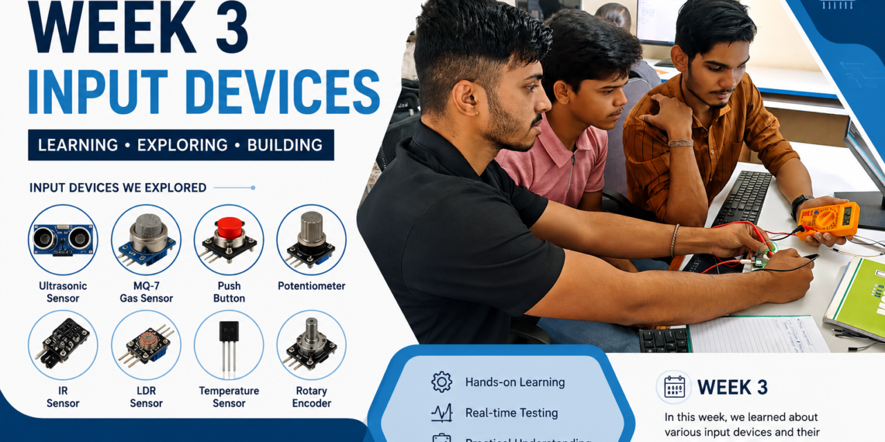
This week, I learned about different input devices and sensors used in embedded systems. I studied the internal structure of sensors and understood how they detect changes in the surrounding environment and convert them into electrical signals. I also learned the difference between analog and digital signals and how they are used in electronic circuits. In addition, I explored an oscilloscope and observed how it displays different types of electrical signals. These topics helped me develop a better understanding of how embedded systems receive, process, and respond to real-world data.
Input Devices
Input devices are electronic components that collect information from the surrounding environment and send it to a microcontroller or computer. They help an embedded system detect changes such as temperature, light, motion, pressure, sound, or the presence of an object. The received data is then processed by the microcontroller, which takes the required action based on the program. Input devices are an important part of embedded systems because they allow the system to interact with the real world.
What is Sensor :-
A sensor is an electronic device that detects changes in the surrounding environment and converts them into an electrical signal. It sends this signal to a microcontroller or other processing device for further action. Sensors can detect physical parameters such as temperature, light, pressure, motion, gas, humidity, and distance. They are widely used in embedded systems to collect real-world data and help the system respond automatically.

Analog Signal
An analog signal is a continuous signal that changes smoothly over time. It can have many different voltage values within a specific range. Analog signals are commonly produced by sensors such as temperature sensors, LDRs, and gas sensors.
Digital Signal
A digital signal is a signal that has only two states: HIGH (1) and LOW (0). It does not change continuously like an analog signal. Digital signals are commonly used by devices such as push buttons, IR sensors, and PIR motion sensors.

SENSORS
1.LDR (Light Dependent Resistor)
An LDR (Light Dependent Resistor) is a light-sensitive sensor that detects the intensity of light. Its resistance changes according to the amount of light falling on its surface. In bright light, the resistance decreases, while in darkness, the resistance increases. LDR sensors are commonly used in embedded systems for automatic light detection and control.

Applications of LDR Sensor
- Automatic street light systems
- Automatic garden lights
- Light intensity measurement
- Solar tracking systems
- Smart home lighting control
- Camera light meters
- Day and night detection systems
- Security and alarm systems
2.LM35 Temperature Sensor
The LM35 is an analog temperature sensor that measures temperature in degrees Celsius (°C). It converts temperature into an analog voltage that can be read by a microcontroller or other electronic devices. The sensor provides an output of 10 mV for every 1°C increase in temperature. It is widely used because it is accurate, easy to use, and does not require additional calibration.

Applications of LM35 Temperature Sensor
- Room temperature monitoring
- Weather monitoring systems
- Water temperature measurement
- Smart home automation
- Industrial temperature monitoring
- Air conditioning and HVAC systems
- Medical devices
- IoT and embedded system projects
- Battery temperature monitoring
- Fire and heat detection systems
3.DHT11 Temperature and Humidity Sensor
The DHT11 is a digital sensor that measures both temperature and humidity. It provides digital output, making it easy to connect with microcontrollers such as Arduino, ESP32, and Raspberry Pi Pico. The sensor is low-cost, simple to use, and suitable for basic environmental monitoring projects. It is commonly used in embedded systems and IoT applications to monitor indoor temperature and humidity.

Applications of DHT11 Sensor
- Weather monitoring systems
- Smart home automation
- Indoor temperature and humidity monitoring
- Greenhouse monitoring
- IoT projects
- Home weather stations
- Air conditioning and HVAC systems
- Data logging systems
- Environmental monitoring
- Educational and embedded system projects
4.Ultrasonic Sensor
An ultrasonic sensor is a distance-measuring sensor that uses ultrasonic sound waves to detect objects. It works by transmitting ultrasonic waves and measuring the time taken for the echo to return after hitting an object. Using this time, the sensor calculates the distance between the sensor and the object. It is widely used because it provides accurate and non-contact distance measurement.

Applications of Ultrasonic Sensor
- Distance measurement
- Obstacle detection in robots
- Water level monitoring
- Automatic parking systems
- Smart dustbins
- Object detection systems
- Security and alarm systems
- Industrial automation
- Drone obstacle avoidance
- IoT and embedded system projects
5.PIR (Passive Infrared) Sensor
A PIR (Passive Infrared) sensor is a motion detection sensor that detects the movement of people or animals by sensing changes in infrared (IR) radiation. It does not emit any signals; instead, it detects the heat naturally emitted by living objects. When movement is detected, the sensor sends a digital signal to the microcontroller. PIR sensors are widely used because they provide reliable and low-power motion detection.

Applications of PIR Sensor
- Motion detection systems
- Automatic lighting systems
- Home security systems
- Burglar alarms
- Smart home automation
- Automatic doors
- Occupancy detection
- Energy-saving lighting control
- IoT and embedded system projects
- Surveillance and monitoring systems
6.IR (Infrared) Sensor
An IR (Infrared) sensor is an electronic sensor that detects the presence of an object using infrared light. It consists of an IR transmitter that emits infrared rays and an IR receiver that detects the reflected rays. When an object comes in front of the sensor, the reflected infrared light is detected, and the sensor sends a digital signal to the microcontroller. IR sensors are widely used for object detection and obstacle sensing in embedded systems.

Applications of IR Sensor
- Obstacle detection in robots
- Object detection systems
- Automatic doors
- Line follower robots
- Smart parking systems
- Security and alarm systems
- Automatic counting systems
- Home automation
- IoT and embedded system projects
- Industrial automation
7.Soil Moisture Sensor
A soil moisture sensor is an electronic sensor that measures the moisture level in the soil. It works by detecting the electrical conductivity between its metal probes, which changes depending on the amount of water in the soil. The sensor provides analog or digital output that can be read by a microcontroller. It is widely used for monitoring soil moisture and automating irrigation systems.

Applications of Soil Moisture Sensor
- Smart irrigation systems
- Automatic plant watering systems
- Agriculture monitoring
- Greenhouse automation
- Garden moisture monitoring
- Soil condition monitoring
- Water conservation systems
- IoT and embedded system projects
- Precision farming
- Environmental monitoring
8.MQ-2 Gas Sensor
The MQ-2 is a gas sensor that detects the presence of combustible gases and smoke in the surrounding environment. It can detect gases such as LPG, methane, propane, hydrogen, and smoke. The sensor provides both analog and digital outputs, which can be read by a microcontroller. It is widely used in gas leakage detection and safety monitoring systems because it is reliable, easy to use, and cost-effective.

Applications of MQ-2 Gas Sensor
- Gas leakage detection systems
- Smoke detection systems
- Fire safety systems
- Home gas monitoring
- Industrial gas monitoring
- Air quality monitoring
- Smart home automation
- IoT and embedded system projects
- Kitchen safety systems
- Environmental monitoring
Group Assignment
During this group assignment, we discussed different types of sensors used in embedded systems and their importance in real-world applications. We learned about the working principle of each sensor and understood how it detects changes in the surrounding environment. We also studied the internal structure of different sensors to understand how they convert physical changes into electrical signals. In addition, we learned the difference between analog and digital outputs and how these signals are sent to a microcontroller for processing. This group discussion improved our understanding of sensor operation and helped us connect theoretical concepts with practical applications in embedded systems.


sensor we discussed in this assignment
1.Rain Sensor

| Pin | Name | Description |
|---|---|---|
| 1 | AO | Analog Output (Moisture Level) |
| 2 | DO | Digital Output (HIGH/LOW) |
| 3 | GND | Ground (0V) |
| 4 | VCC | Power Supply (3.3V–5V) |
OUTPUT
| Output | Type | Description |
|---|---|---|
| AO | Analog | Provides a continuous value based on the amount of water. |
| DO | Digital | Provides HIGH or LOW depending on the preset threshold. |
Working Principle of Rain Sensor
A rain sensor works by detecting water droplets on its sensing plate. When rain falls on the metal tracks of the sensing plate, the electrical conductivity between the tracks increases. This change is processed by the sensor module and converted into analog and digital signals. The analog output changes according to the amount of water, while the digital output changes to HIGH or LOW based on the threshold set using the onboard potentiometer.
Internal Structure of Rain Sensor
- Sensing Plate: Detects rain or water droplets by measuring changes in electrical conductivity.
- LM393 Comparator: Compares the sensor signal and generates the digital output.
- Potentiometer: Adjusts the sensitivity of the rain sensor.
- Power LED: Indicates that the sensor module is powered ON.
- Output LED: Turns ON when rain is detected.
- AO (Analog Output): Provides a continuous output based on the amount of water.
- DO (Digital Output): Provides a HIGH or LOW signal based on the preset threshold.
- VCC and GND Pins: Supply power to the sensor module.
Applications of Rain Sensor
- Automatic rain detection systems
- Smart irrigation systems
- Weather monitoring stations
- Automatic windshield wipers
- Smart home automation
- Roof and window control systems
- Rainwater harvesting systems
- IoT and embedded system projects
- Industrial monitoring systems
- Environmental monitoring
2. Hall effect

| Pin | Name | Description |
|---|---|---|
| 1 | VCC | Power Supply (3.3V–5V) |
| 2 | GND | Ground (0V) |
| 3 | OUT | Digital Output Signal |
OUTPUT
| Condition | Digital Output (OUT) |
|---|---|
| No Magnetic Field | HIGH (1) |
| Magnetic Field Detected | LOW (0) |
Working Principle of Hall Effect Sensor
A Hall Effect Sensor works by detecting the presence of a magnetic field. When no magnet is near the sensor, the output remains HIGH. When a magnet comes close to the sensor, it detects the magnetic field and changes the output to LOW. This change in output is read by the microcontroller to detect the presence of a magnet or moving object.
Internal Structure of Hall Effect Sensor
- Hall Element: Detects the magnetic field and generates the Hall voltage.
- Voltage Regulator: Provides a stable operating voltage to the sensor.
- Signal Amplifier: Amplifies the weak Hall voltage generated by the Hall element.
- Schmitt Trigger (Comparator): Converts the amplified signal into a clean digital output.
- Output Transistor: Produces the final HIGH or LOW output signal.
- VCC Pin: Supplies power to the sensor.
- GND Pin: Provides the ground connection.
- OUT Pin: Sends the digital output signal to the microcontroller.
Applications of Hall Effect Sensor
- Speed measurement systems
- Wheel speed sensors
- Position detection
- Proximity sensing
- Magnetic field detection
- Brushless DC (BLDC) motors
- Door open/close detection
- Industrial automation
- IoT and embedded system projects
- Robotics and automation
3.Flame Sensor

| Pin | Name | Description |
|---|---|---|
| 1 | AO | Analog Output |
| 2 | GND | Ground (0V) |
| 3 | VCC | Power Supply (3.3V–5V) |
| 4 | DO | Digital Output |
OUTPUT
| Output Pin | Signal Type | Description |
|---|---|---|
| AO | Analog Output | Provides a continuous value based on the intensity of the flame. |
| DO | Digital Output | Provides HIGH (1) when no flame is detected and LOW (0) when a flame is detected (based on the threshold set by the potentiometer). |
Working Principle of Flame Sensor
A flame sensor works by detecting infrared (IR) light emitted by a flame. When a flame is present, the sensor detects the infrared radiation and converts it into an electrical signal. The control circuit processes this signal and provides analog and digital outputs. The analog output changes according to the flame intensity, while the digital output changes to HIGH or LOW based on the threshold set using the onboard potentiometer.
Internal Structure of Flame Sensor
- Infrared (IR) Photodiode: Detects infrared light emitted by a flame.
- LM393 Comparator: Compares the sensor signal and generates the digital output.
- Potentiometer: Adjusts the flame detection sensitivity.
- Power LED: Indicates that the sensor module is powered ON.
- Output LED: Turns ON when a flame is detected.
- AO (Analog Output): Provides a continuous output based on the flame intensity.
- DO (Digital Output): Provides a HIGH or LOW signal based on the preset threshold.
- VCC and GND Pins: Supply power to the sensor module.
Applications of Flame Sensor
- Fire detection systems
- Fire alarm systems
- Industrial safety monitoring
- Gas stove flame detection
- Smart home safety systems
- Forest fire monitoring
- Robotics and automation
- IoT and embedded system projects
- Laboratory flame detection
- Emergency warning systems
4.Sound Sensor

| Pin | Name | Description |
|---|---|---|
| 1 | AO | Analog Output |
| 2 | GND | Ground (0V) |
| 3 | VCC | Power Supply (3.3V–5V) |
OUTPUT
| Output Pin | Signal Type | Description |
|---|---|---|
| AO | Analog Output | Provides a continuous value based on the sound intensity. |
| DO | Digital Output | Provides HIGH (1) when the sound level is below the preset threshold and LOW (0) when the sound level exceeds the threshold set by the potentiometer. |
Working Principle of Sound Sensor
A sound sensor works by detecting sound waves using an onboard microphone. The microphone converts sound into an electrical signal, which is processed by the sensor module. The module provides analog and digital outputs. The analog output changes according to the sound intensity, while the digital output changes to HIGH or LOW based on the threshold set using the onboard potentiometer.
Internal Structure of Sound Sensor
- Microphone (Electret Microphone): Detects sound waves and converts them into electrical signals.
- Signal Amplifier: Amplifies the weak signal from the microphone.
- LM393 Comparator: Compares the signal and generates the digital output.
- Potentiometer: Adjusts the sound detection sensitivity.
- Power LED: Indicates that the sensor module is powered ON.
- Output LED: Turns ON when the sound level exceeds the preset threshold.
- AO (Analog Output): Provides a continuous output based on the sound intensity.
- DO (Digital Output): Provides a HIGH or LOW signal based on the preset threshold.
- VCC and GND Pins: Supply power to the sensor module.
Applications of Sound Sensor
- Clap switch systems
- Noise level monitoring
- Voice-activated devices
- Home security systems
- Smart home automation
- Sound detection alarms
- Robotics and automation
- IoT and embedded system projects
- Industrial sound monitoring
- Audio-triggered lighting systems
Comparison Between DHT11 and DHT22
DHT11 Sensor
The DHT11 is a digital sensor that measures temperature and humidity. It provides digital output, making it easy to interface with microcontrollers such as Arduino, ESP32, and Raspberry Pi Pico. The sensor is low-cost, easy to use, and suitable for basic environmental monitoring projects.
DHT22 Sensor
The DHT22 is an advanced digital temperature and humidity sensor with higher accuracy and a wider measurement range than the DHT11. It provides precise digital output and is suitable for applications that require reliable environmental monitoring. The DHT22 is commonly used in weather stations, industrial systems, smart home automation, and IoT projects.


| Feature | DHT11 | DHT22 |
|---|---|---|
| Temperature Range | 0°C to 50°C | -40°C to 80°C |
| Humidity Range | 20% to 80% RH | 0% to 100% RH |
| Temperature Accuracy | ±2°C | ±0.5°C |
| Humidity Accuracy | ±5% RH | ±2% RH |
| Resolution | 1°C, 1% RH | 0.1°C, 0.1% RH |
| Output Type | Digital | Digital |
| Sampling Rate | 1 reading/second | 2 readings/second |
| Power Supply | 3.3V–5V | 3.3V–6V |
| Cost | Low | Higher |
| Applications | Basic temperature and humidity monitoring | High-accuracy weather stations, industrial and IoT applications |
Testing Voltage and Cureent of IR Sensor
In this activity, we interfaced an IR sensor with an Arduino board to detect the presence of an object. The sensor was connected using the VCC, GND, and OUT pins. When an object came in front of the sensor, it sent a digital signal to the Arduino, which performed the programmed action. We also measured the voltage and current of the IR sensor using a multimeter to verify its operation and understand its electrical characteristics. This activity helped us understand sensor interfacing, digital signal processing, and basic electrical measurements using Arduino.


Observing Waveforms Using an Oscilloscope
In this activity, we learned how to use an oscilloscope to observe electrical signals. We viewed different waveforms and understood how signals change over time. We also learned how the oscilloscope displays voltage with respect to time, helping us analyze signal behavior. This activity improved our understanding of analog and digital waveforms and their practical applications in electronics and embedded systems.


Indiviual Assignment
In this individual assignment, I interfaced different sensors with Arduino Uno, ESP32, Seeed XIAO RP2040, and ESP32-C3 boards. I connected each sensor correctly and tested its output by writing and uploading the required programs. I also interfaced a buzzer with these boards and controlled it based on the sensor output. This activity helped me understand sensor interfacing, GPIO connections, and how different development boards communicate with sensors and actuators.
Sensors Connect With Arduino
1. Ultrasonic sensor with buzzer
In this individual assignment, I interfaced an ultrasonic sensor with an Arduino Uno to measure the distance of nearby objects. The ultrasonic sensor continuously detected the distance and sent the measured data to the Arduino for processing. The measured distance was also displayed on the Arduino Serial Monitor for real-time monitoring. Based on the programmed distance range, the Arduino controlled a buzzer by turning it ON when an object was detected within the specified distance and OFF when the object moved away. This activity helped me understand ultrasonic sensor interfacing, distance measurement, Serial Monitor output, and controlling an output device using Arduino.


CODE
const int trigPin = 9;
const int echoPin = 10;
const int buzzerPin = 8;

long duration;
float distance;

void setup() {
  pinMode(trigPin, OUTPUT);
  pinMode(echoPin, INPUT);
  pinMode(buzzerPin, OUTPUT);

  Serial.begin(9600);
}

void loop() {

  // Send ultrasonic pulse
  digitalWrite(trigPin, LOW);
  delayMicroseconds(2);

  digitalWrite(trigPin, HIGH);
  delayMicroseconds(10);

  digitalWrite(trigPin, LOW);

  // Read echo
  duration = pulseIn(echoPin, HIGH);

  // Calculate distance
  distance = duration * 0.034 / 2;

  Serial.print("Distance: ");
  Serial.print(distance);
  Serial.println(" cm");

  if (distance > 0 && distance <= 20) {   // Object within 20 cm

    Serial.println("Object Detected!");
    digitalWrite(buzzerPin, HIGH);

  } else {

    Serial.println("No Object");
    digitalWrite(buzzerPin, LOW);

  }

  delay(500);
}
2. PIR Sensor with Buzzer
I interfaced a PIR sensor with an Arduino Uno to detect motion. When the sensor detected motion, it sent a digital signal to the Arduino, which turned the buzzer ON. When no motion was detected, the buzzer turned OFF. The sensor status was also displayed on the Serial Monitor. This activity helped me understand PIR sensor interfacing, motion detection, and buzzer control using Arduino.


CODE
const int pirPin = 2;
const int buzzerPin = 8;

void setup() {
  pinMode(pirPin, INPUT);
  pinMode(buzzerPin, OUTPUT);

  Serial.begin(9600);
  Serial.println("PIR Motion Detection System Ready...");
}

void loop() {

  int motion = digitalRead(pirPin);

  if (motion == HIGH) {

    Serial.println("Motion Detected!");
    digitalWrite(buzzerPin, HIGH);

  } else {

    Serial.println("No Motion");
    digitalWrite(buzzerPin, LOW);

  }

  delay(500);
}
3. smoke sesnor with buzzer
I can use MQ-2 smoke sensor with an Arduino Uno to detect smoke and combustible gases. The sensor continuously monitored the surrounding air and sent its output to the Arduino. When smoke was detected above the preset threshold, the Arduino turned the buzzer ON. When no smoke was detected, the buzzer remained OFF. The sensor status was also displayed on the Serial Monitor. This activity helped me understand smoke sensor interfacing, gas detection, Serial Monitor output, and buzzer control using Arduino.


CODE
const int mq2Pin = A0;
const int buzzerPin = 8;

int sensorValue = 0;
int threshold = 300;   // Change this value if needed

void setup() {
  pinMode(buzzerPin, OUTPUT);
  Serial.begin(9600);

  Serial.println("MQ-2 Smoke Detection System");
}

void loop() {

  sensorValue = analogRead(mq2Pin);

  Serial.print("Sensor Value: ");
  Serial.println(sensorValue);

  if (sensorValue > threshold) {
    Serial.println("Smoke Detected!");
    digitalWrite(buzzerPin, HIGH);
  } else {
    Serial.println("Air is Normal");
    digitalWrite(buzzerPin, LOW);
  }

  delay(500);
}
4. Sound Sensor with Buzzer
I connected a sound sensor with an Arduino Uno to detect sound. The Arduino continuously read the sensor output and displayed the sensor status on the Serial Monitor. When a loud sound was detected, the Arduino turned the buzzer ON. When no sound was detected, the buzzer remained OFF. This activity helped me understand sound sensor interfacing, sound detection, Serial Monitor monitoring, and controlling a buzzer using Arduino.


CODE
const int soundPin = 2;
const int buzzerPin = 8;

void setup() {
  pinMode(soundPin, INPUT);
  pinMode(buzzerPin, OUTPUT);
  Serial.begin(9600);

  Serial.println("Sound Sensor Ready...");
}

void loop() {

  if (digitalRead(soundPin) == LOW) {

    Serial.println("Sound Detected!");
    digitalWrite(buzzerPin, HIGH);
    delay(200);
    digitalWrite(buzzerPin, LOW);
    delay(200);

  } else {

    Serial.println("No Sound");
    digitalWrite(buzzerPin, LOW);
  }

  delay(100);
}
5. Float Sensor on Buzzer
A float sensor was connected to an Arduino Uno to detect the water level. The Arduino continuously read the sensor output and displayed the sensor status on the Serial Monitor. When the water level reached the float sensor, the Arduino turned the buzzer ON. When the water level dropped below the sensor, the buzzer turned OFF. This activity helped me understand float sensor interfacing, water level detection, Serial Monitor monitoring, and buzzer control using Arduino.


CODE
const int floatPin = 2;
const int buzzerPin = 8;

void setup() {
  pinMode(floatPin, INPUT_PULLUP);
  pinMode(buzzerPin, OUTPUT);

  Serial.begin(9600);
  Serial.println("Float Sensor Ready...");
}

void loop() {

  int state = digitalRead(floatPin);

  if (state == LOW) {
    Serial.println("Water Level Detected!");
    digitalWrite(buzzerPin, LOW);
  }
  else {
    Serial.println("Water Level Low!");
    digitalWrite(buzzerPin, HIGH);
  }

  delay(500);
}
6. RFID Sensor on Buzzer
I connected an RFID module with an Arduino Uno to read RFID cards. When I placed an RFID card near the reader, the Arduino detected the card and displayed its unique ID on the Serial Monitor. After reading the card, the buzzer turned ON for a short time to indicate that the card was detected. This activity helped me understand RFID interfacing, card detection, Serial Monitor output, and buzzer control using Arduino.


CODE
#include <SPI.h>
#include <MFRC522.h>

#define SS_PIN 10
#define RST_PIN 9
#define BUZZER_PIN 8

MFRC522 rfid(SS_PIN, RST_PIN);

void setup() {
  Serial.begin(9600);
  SPI.begin();
  rfid.PCD_Init();

  pinMode(BUZZER_PIN, OUTPUT);
  digitalWrite(BUZZER_PIN, LOW);

  Serial.println("Place your RFID Card...");
}

void loop() {

  // Check if a new card is present
  if (!rfid.PICC_IsNewCardPresent())
    return;

  // Read the card
  if (!rfid.PICC_ReadCardSerial())
    return;

  Serial.print("Card UID: ");

  for (byte i = 0; i < rfid.uid.size; i++) {
    Serial.print(rfid.uid.uidByte[i], HEX);
    Serial.print(" ");
  }

  Serial.println();
  Serial.println("Card Detected!");

  // Turn buzzer ON
  digitalWrite(BUZZER_PIN, HIGH);
  delay(1000);
  digitalWrite(BUZZER_PIN, LOW);

  rfid.PICC_HaltA();
  rfid.PCD_StopCrypto1();
}
Experince with Arduino UNO
During these activities, I gained practical experience in interfacing different sensors with the Arduino Uno. I worked with sensors such as the IR sensor, PIR sensor, ultrasonic sensor, MQ-2 smoke sensor, sound sensor, float sensor, and RFID module. I learned how to connect sensors, read their outputs, and control a buzzer based on different sensor conditions. I also observed the sensor data on the Serial Monitor and understood how digital and analog signals are processed by the Arduino. These hands-on activities improved my skills in circuit connections, programming, debugging, and testing embedded system projects. Overall, this experience increased my confidence in working with sensors and Arduino-based applications.
Sensors Connection with Seed XIAO ESP32-C3
After completing the Arduino activities, I started working with the Seeed XIAO ESP32-C3 development board. I interfaced different sensors with the board and wrote programs to read their outputs. I learned how to connect sensors, upload programs, and test their working on the ESP32-C3. I also observed the sensor output and understood how the board processes digital and analog signals. These practical activities improved my programming, debugging, and hardware interfacing skills and gave me confidence in working with ESP32-C3-based embedded system projects.
1.Ultrasonic Sensor
I connected an ultrasonic sensor with the Seeed XIAO ESP32-C3 to measure the distance of nearby objects. The sensor continuously measured the distance and sent the data to the ESP32-C3. The measured distance was displayed on the Serial Monitor for real-time monitoring. This activity helped me understand ultrasonic sensor interfacing, distance measurement, Serial Monitor output, and programming using the Seeed XIAO ESP32-C3.


CODE
const int trigPin = 2;   // D2
const int echoPin = 3;   // D3

long duration;
float distance;

void setup() {
  pinMode(trigPin, OUTPUT);
  pinMode(echoPin, INPUT);

  Serial.begin(115200);
}

void loop() {

  // Send ultrasonic pulse
  digitalWrite(trigPin, LOW);
  delayMicroseconds(2);

  digitalWrite(trigPin, HIGH);
  delayMicroseconds(10);

  digitalWrite(trigPin, LOW);

  // Read echo time
  duration = pulseIn(echoPin, HIGH);

  // Calculate distance
  distance = duration * 0.0343 / 2;

  Serial.print("Distance: ");
  Serial.print(distance);
  Serial.println(" cm");

  delay(500);
}
2. PIR Motion Sensor
I connected a PIR motion sensor with the Seeed XIAO ESP32-C3 to detect human motion. The sensor continuously monitored the surrounding area and sent a digital signal to the ESP32-C3 whenever motion was detected. The sensor status was displayed on the Serial Monitor for real-time monitoring. This activity helped me understand PIR sensor interfacing, motion detection, Serial Monitor output, and programming using the Seeed XIAO ESP32-C3.


CODE
const int pirPin = 2;   // PIR OUT connected to GPIO2

void setup() {
  pinMode(pirPin, INPUT);

  Serial.begin(115200);
  Serial.println("PIR Motion Detection System Ready...");
}

void loop() {

  int motion = digitalRead(pirPin);

  if (motion == HIGH) {

    Serial.println("Motion Detected!");

  } else {

    Serial.println("No Motion");

  }

  delay(500);
}
3.Sound Sensor
I connected a sound sensor with the Seeed XIAO ESP32-C3 to detect sound. The sensor continuously monitored the surrounding sound level and sent its output to the ESP32-C3. The sensor status was displayed on the Serial Monitor whenever sound was detected. This activity helped me understand sound sensor interfacing, sound detection, Serial Monitor output, and programming using the Seeed XIAO ESP32-C3.


CODE
const int soundPin = 2;   // Sound Sensor DO connected to GPIO2

void setup() {
  pinMode(soundPin, INPUT);

  Serial.begin(115200);
  Serial.println("Sound Sensor Ready...");
}

void loop() {

  if (digitalRead(soundPin) == LOW) {

    Serial.println("Sound Detected!");

  } else {

    Serial.println("No Sound");

  }

  delay(100);
}
4. MQ7 Sensor
I connected an MQ-7 gas sensor with the Seeed XIAO ESP32-C3 to detect carbon monoxide (CO) gas. The sensor continuously monitored the surrounding air and sent its output to the ESP32-C3. The sensor readings were displayed on the Serial Monitor for real-time monitoring. This activity helped me understand MQ-7 sensor interfacing, gas detection, Serial Monitor output, and programming using the Seeed XIAO ESP32-C3.


CODE
const int mq7Pin = A0;   // MQ-7 AO connected to A0

void setup() {
  Serial.begin(115200);
  Serial.println("MQ-7 Gas Sensor Ready...");
}

void loop() {

  int sensorValue = analogRead(mq7Pin);

  Serial.print("MQ-7 Value: ");
  Serial.println(sensorValue);

  delay(500);
}
5. Float Sensor
I connected a float sensor with the Seeed XIAO ESP32-C3 to detect the water level. The sensor continuously monitored the water level and sent its output to the ESP32-C3. The sensor status was displayed on the Serial Monitor for real-time monitoring. This activity helped me understand float sensor interfacing, water level detection, Serial Monitor output, and programming using the Seeed XIAO ESP32-C3.


const int floatPin = 2;   // Float Sensor connected to GPIO2

void setup() {
  pinMode(floatPin, INPUT_PULLUP);

  Serial.begin(115200);
  Serial.println("Float Sensor Ready...");
}

void loop() {

  int state = digitalRead(floatPin);

  if (state == LOW) {
    Serial.println("Water Level Detected!");
  } else {
    Serial.println("Water Level Low!");
  }

  delay(500);
}
Overall Experience
Throughout this learning journey, I gained both theoretical knowledge and practical experience in embedded systems and sensor interfacing. I learned about different types of sensors, their working principles, internal structures, analog and digital signals, and how to observe signal waveforms using an oscilloscope. I also interfaced various sensors with Arduino Uno and Seeed XIAO ESP32-C3, wrote programs, tested their outputs on the Serial Monitor, and built simple applications using buzzers and sensors. These hands-on activities improved my programming, circuit connection, debugging, and problem-solving skills. Overall, this experience increased my confidence in developing embedded system and IoT projects.