Introduction
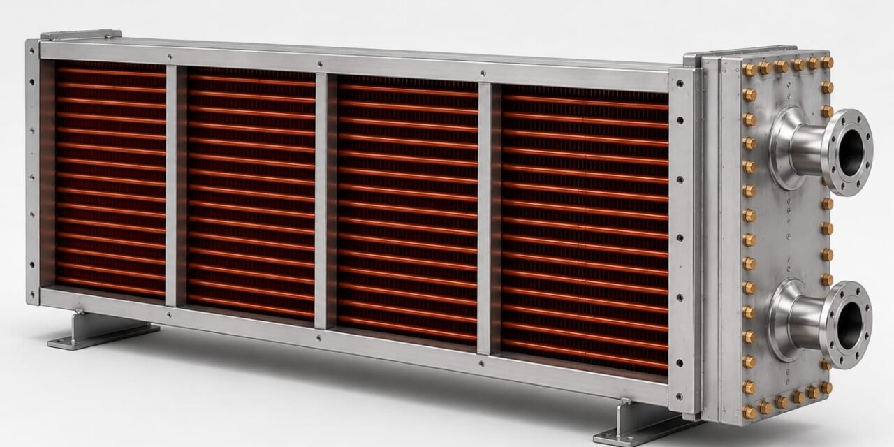
A radiator is a heat exchanger designed to transfer heat from a hot fluid to a colder fluid without direct contact. In drying, we envisage applications where hot water flows through tubes while ambient air passes over finned surfaces. Heat is transferred from the water to the tube walls, then through the fins, and finally to the air.
The use of fins significantly increases the available heat transfer area and arrangement of tubes breaks laminar resulting in higher thermal efficiency. The design of a radiator involves selecting appropriate tube dimensions, fin geometry, tube arrangement, and flow rates to achieve the desired outlet air temperature
week 1
Study the woeking principle of the cross flow radiator (Heat Exchanger)
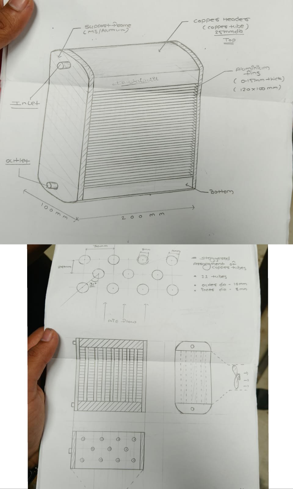
- Hot water from the solar water-heating system flows through 11 staggered copper tubes.
- The copper tubes have an outer diameter of 10 mm and an inner diameter of 8 mm.
- A fan/blower forces air across the tubes in a cross-flow direction.
- Heat is transferred from the hot water to the flowing air through the copper tube walls.
- The tubes are arranged in a staggered pattern with 30 mm horizontal spacing and 25 mm vertical spacing.
- The staggered arrangement increases air–tube contact and improves heat transfer.
- The heated air is then supplied to the drying chamber.
- Tube diameter, wall thickness, and tube length affect water flow and heat transfer.
- Number of tubes, tube pitch, and tube rows determine the total heat-transfer area and water distribution.
- Fin thickness, fin spacing, and fin height increase the heat-transfer surface area and allow effective airflow.
- Proper selection of all design parameters improves heat-transfer efficiency and produces a higher air outlet temperature.
Geometrical parameters
- Tube diameter
- Tube wall thickness
- Tube length
- Number of tubes
- Tube pitch
- Number of tube rows
- Fin thickness
- Fin spacing
- Fin height
Design parameters fianilised, material selection and fabrication
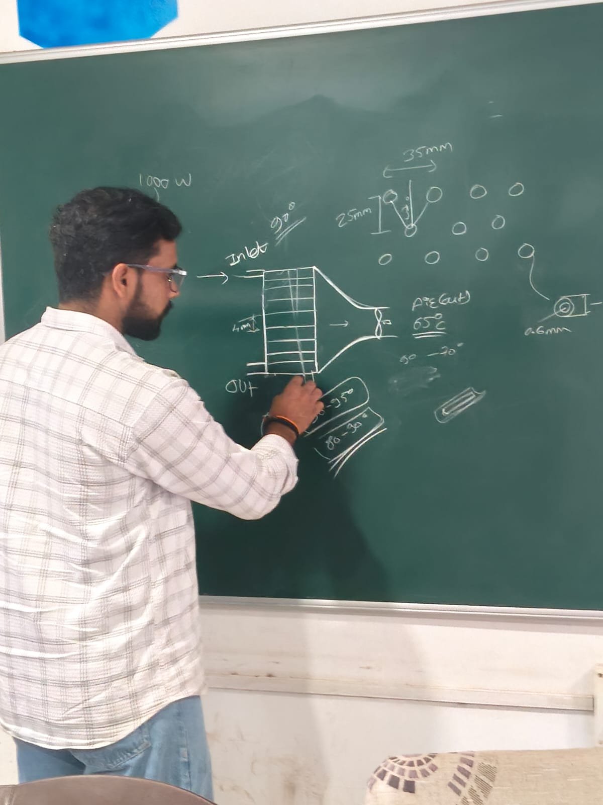
- Design parameters finalized: The heat exchanger has been designed for approximately 1 kW heat transfer capacity.
- Material selection completed: Copper tubes and aluminium fins have been selected for efficient heat transfer.
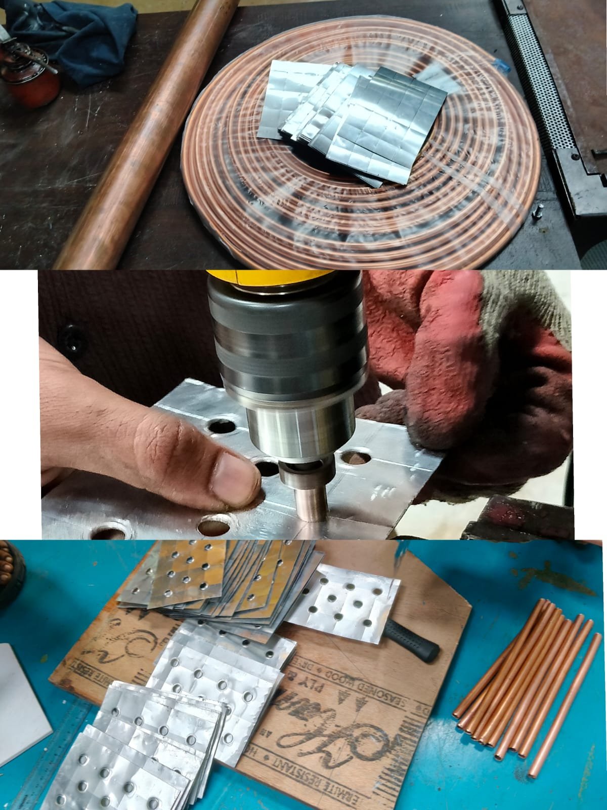
- Copper tube preparation completed: Tubes of 10 mm outer diameter, 8 mm inner diameter, and 200 mm length have been cut and prepared.
- Aluminium fin preparation in progress/completed: Aluminium sheets of 0.16 mm thickness have been cut into the required fin size.
- Fin drilling completed: Holes have been drilled according to the staggered tube arrangement, maintaining approximately 25 mm horizontal pitch and 30 mm vertical pitch.
week 2
Assembly preparation stage
- Design parameters finalized for a 1 kW cross-flow radiator.
- Copper tubes cut to the required 200 mm length.
- Aluminium fins prepared with 0.16 mm thickness.
- Holes made according to the required tube pitch.
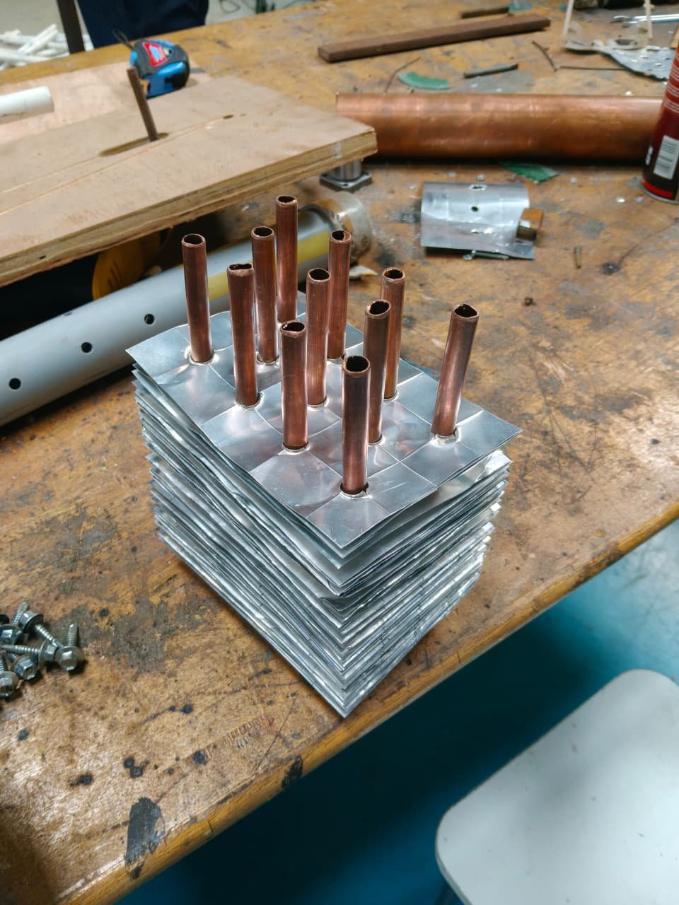
- Tubes arranged in a staggered pattern.
- Tube–fin assembly completed with 4 mm fin spacing.
- Radiator core fabrication is currently in progress.
- Next step: Header connection.
header connection
- Copper pipe was selected for the header of assembly.
- The copper pipe was selected and cut to the required length.
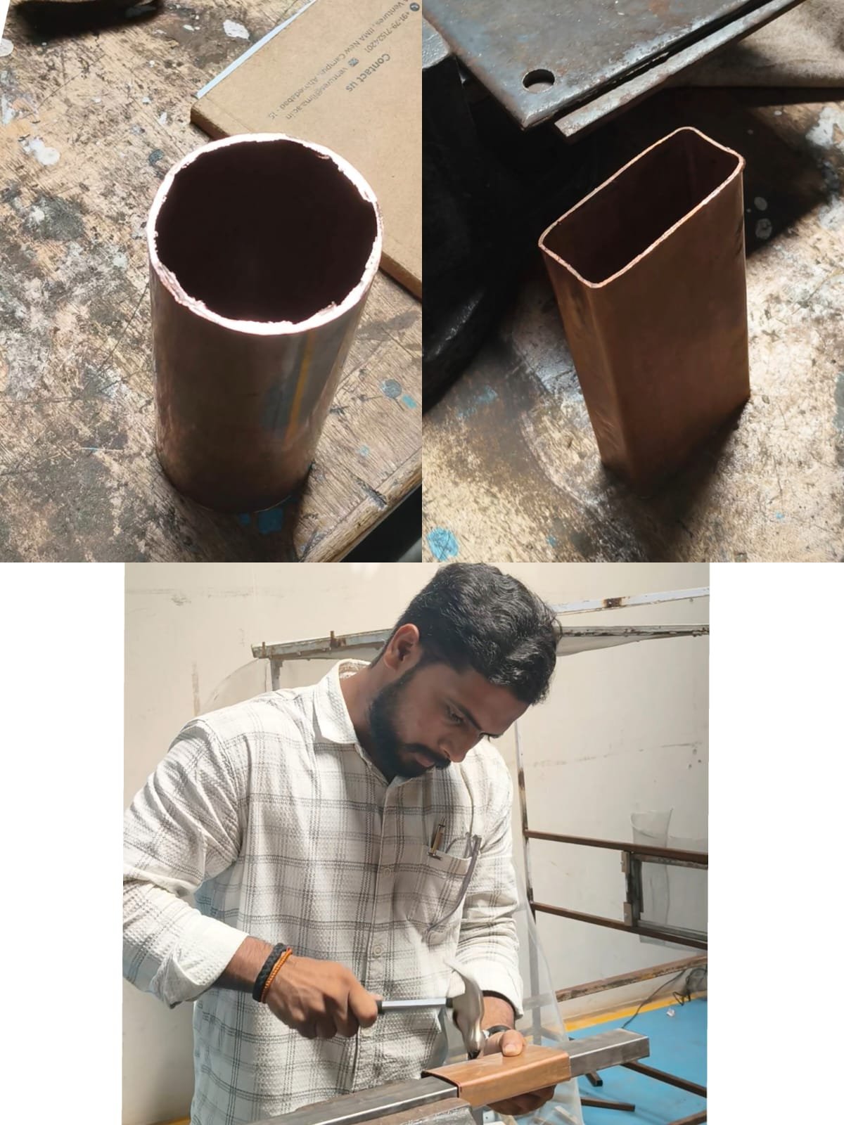
- Initially, the pipe had a circular cross-section.
- The pipe was manually hammered and gradually reshaped.
- The circular pipe was successfully converted into a rectangular-shaped pipe.
- This shaped copper pipe will be used in the fabrication of the radiator-type heat exchanger.
- Next step: Preparation of fins and assembly of the copper tubes with fins and headers.
Preparation of fins and assembly of the copper tubes with fins and headers.
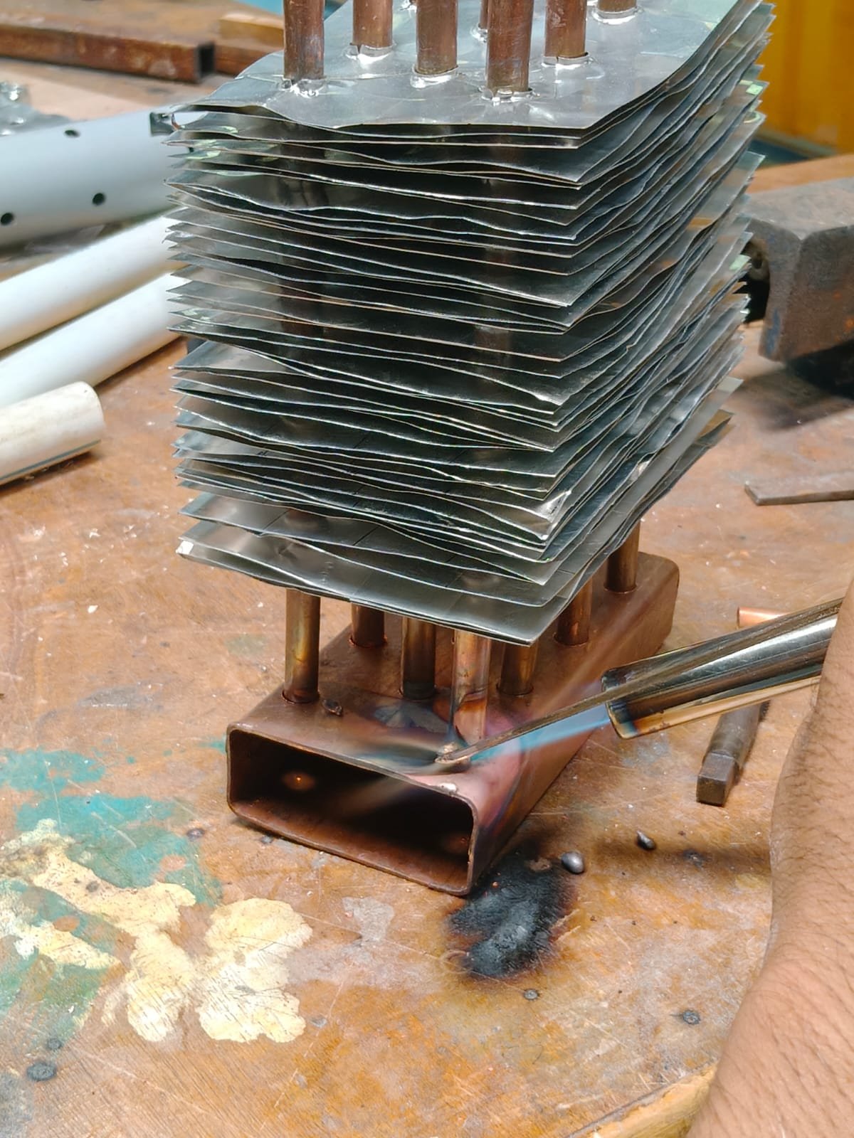
- Header Preparation: The reshaped copper header pipe was prepared for connecting the copper tubes.
- Hole Making: Holes were made in the header according to the required tube arrangement.
- Copper Tube Insertion: The copper tubes were inserted into the prepared holes of the header.
- Fin Assembly: Aluminium fins were placed over the copper tubes to increase the heat-transfer surface area.
- Core Assembly: The tubes, fins, and headers were assembled to form the radiator core.
- Brazing Process: The tube-to-header joints are being brazed to make them strong and leak-proof.
- Present Status: The radiator core fabrication is in progress, and the main components have been successfully assembled.
- Next Step: Complete brazing, check for water leakage, align the fins, and perform thermal performance testing.
week 3
Header & Fin Preparation
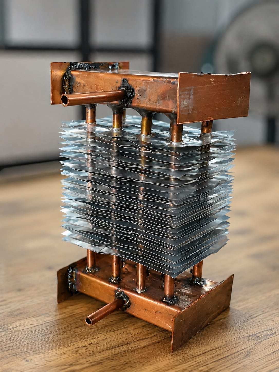
- Copper header plates were cut.
- Header plates were welded.
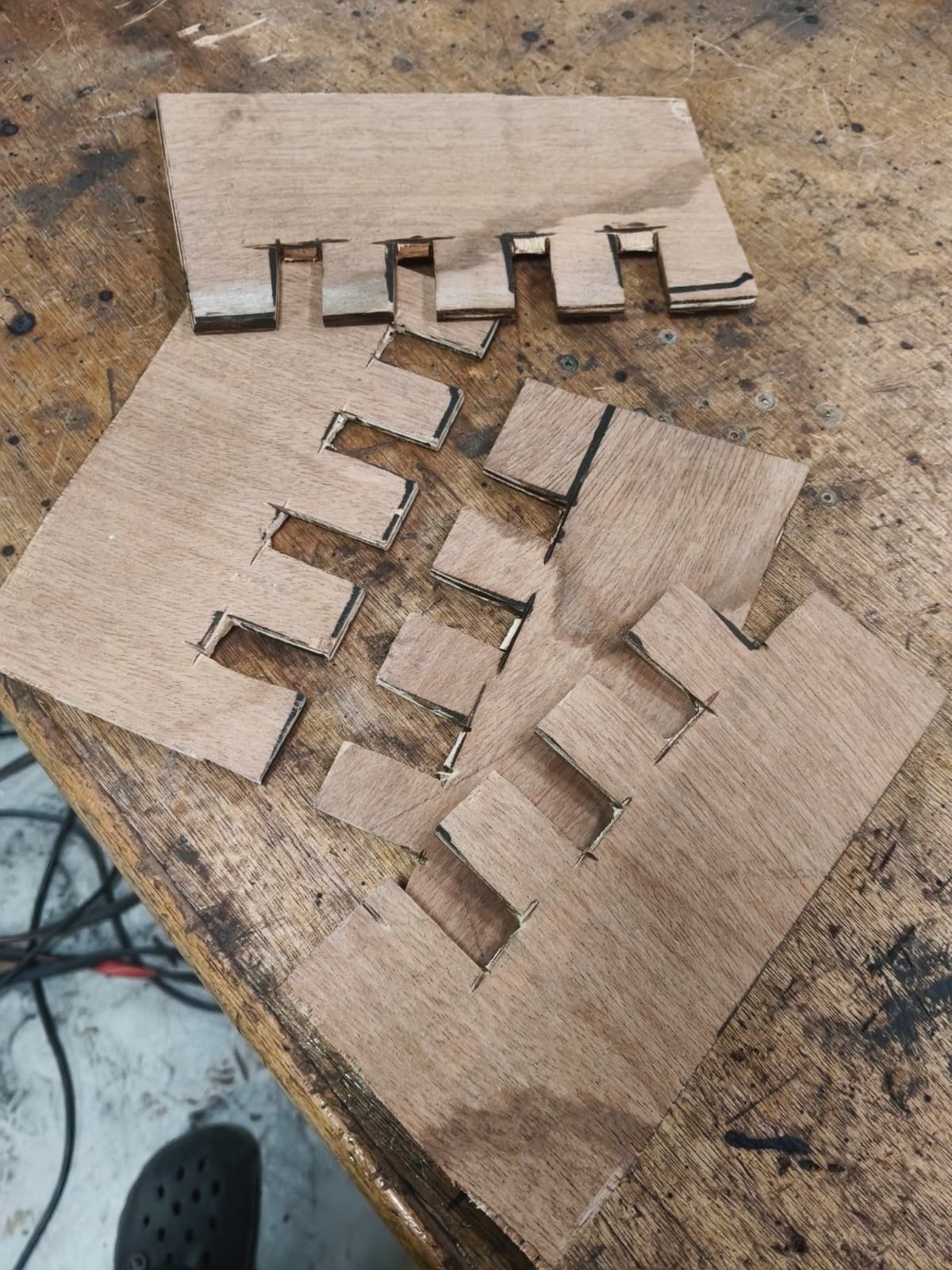
- A plywood template was prepared.
- 4 mm fin spacing was maintained
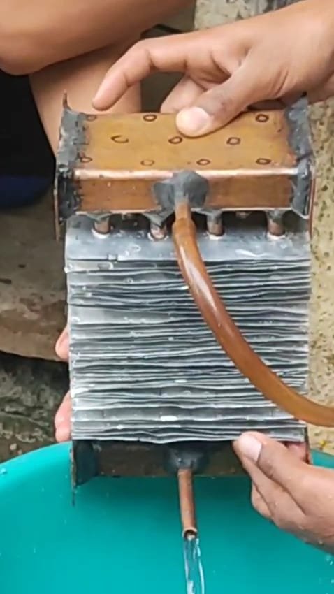
Assembly & Sealing
- The radiator was assembled.
- M-Seal was applied to all joints.
- Joints were checked for proper sealing.
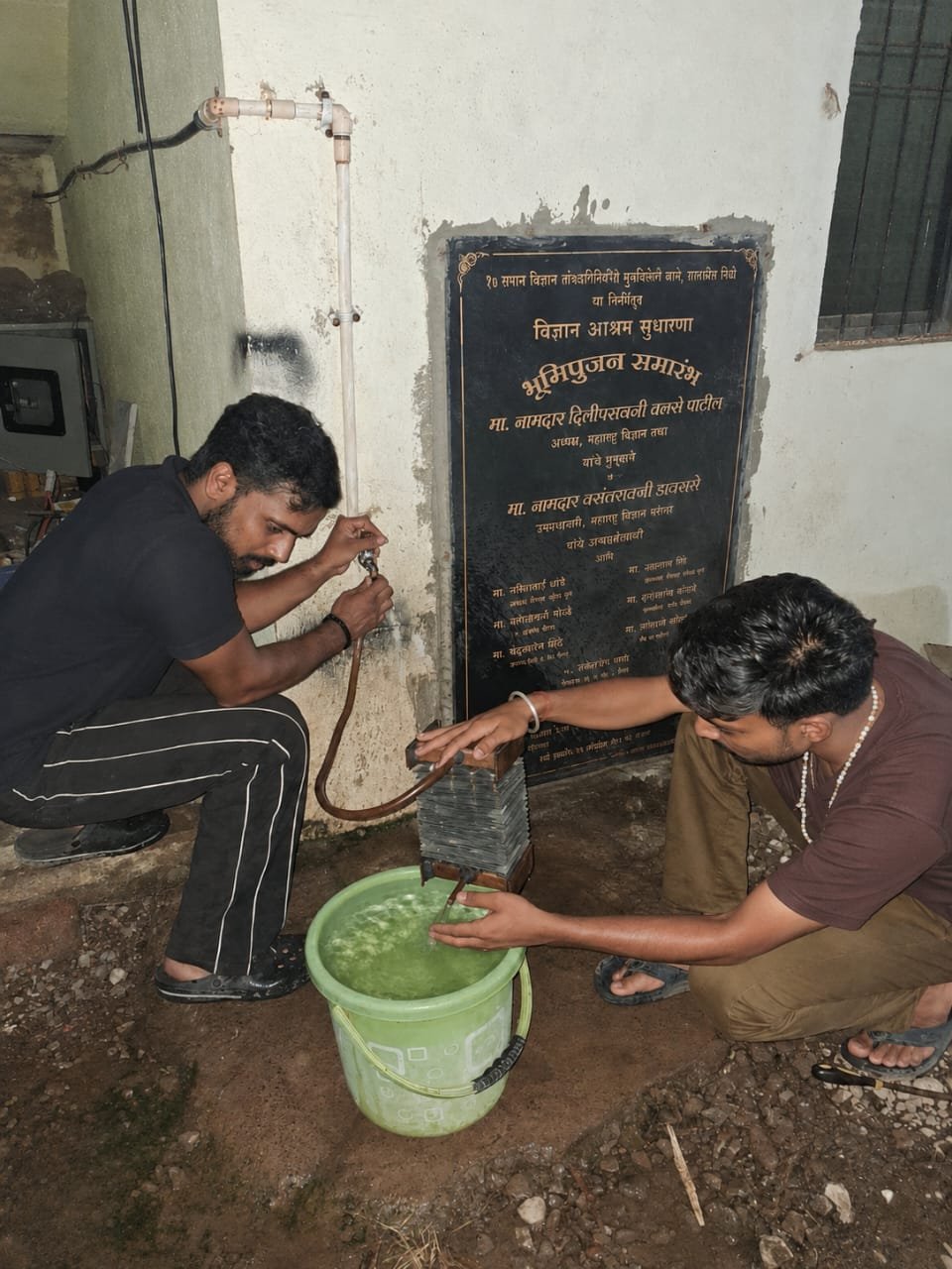
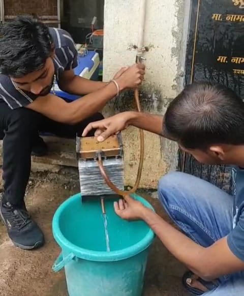
Leakage Testing
- The first leakage test was conducted.
- Leakage points were identified.
- Araldite was applied to repair the leakage.
- The radiator was left for 24 hours to cure.
- A second leakage test showed improved sealing.
Final Fabrication
- Two remaining leakage points were sealed.
- Araldite was again applied to repair the leakage.
- The radiator was left for 24 hours to cure.
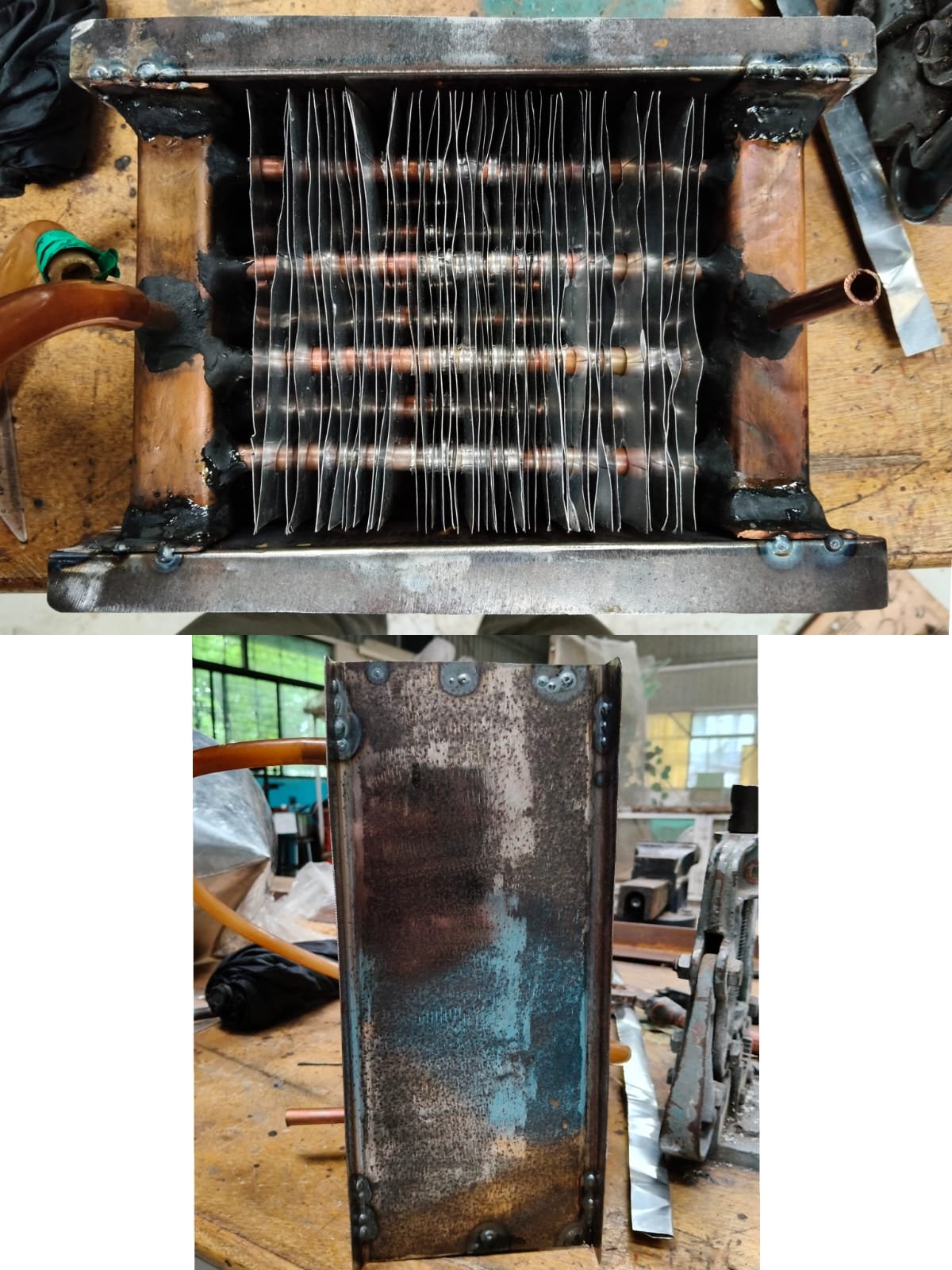
- Metal side plates were welded.
- The fins were protected and the structure was strengthened.
- The prototype is ready for the third leakage test.
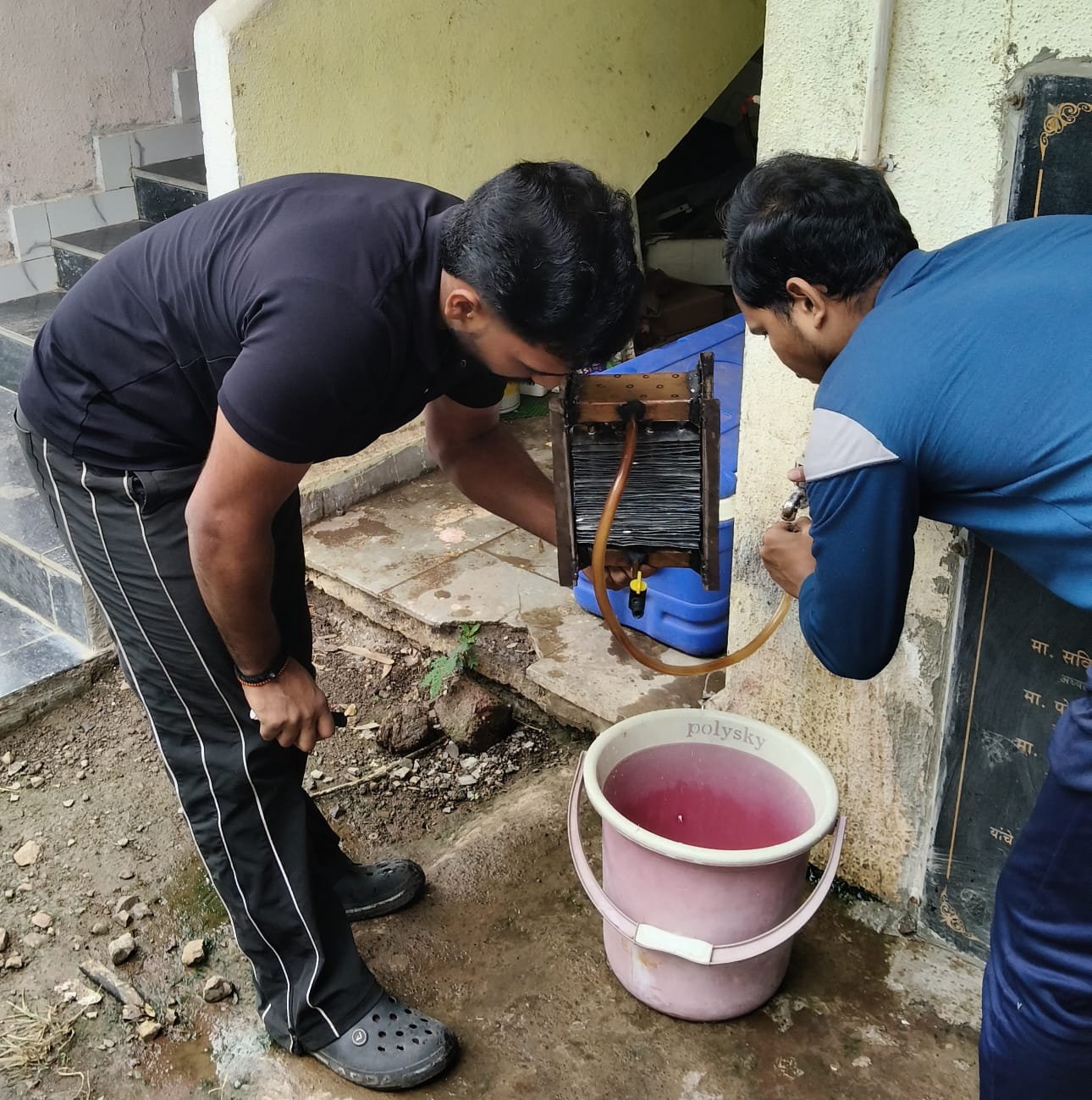
Third leakage test
- The third leakage test was conducted.
- The leakage points was corrected.
- After cure for 24 hours.
- leakages are now negligible.
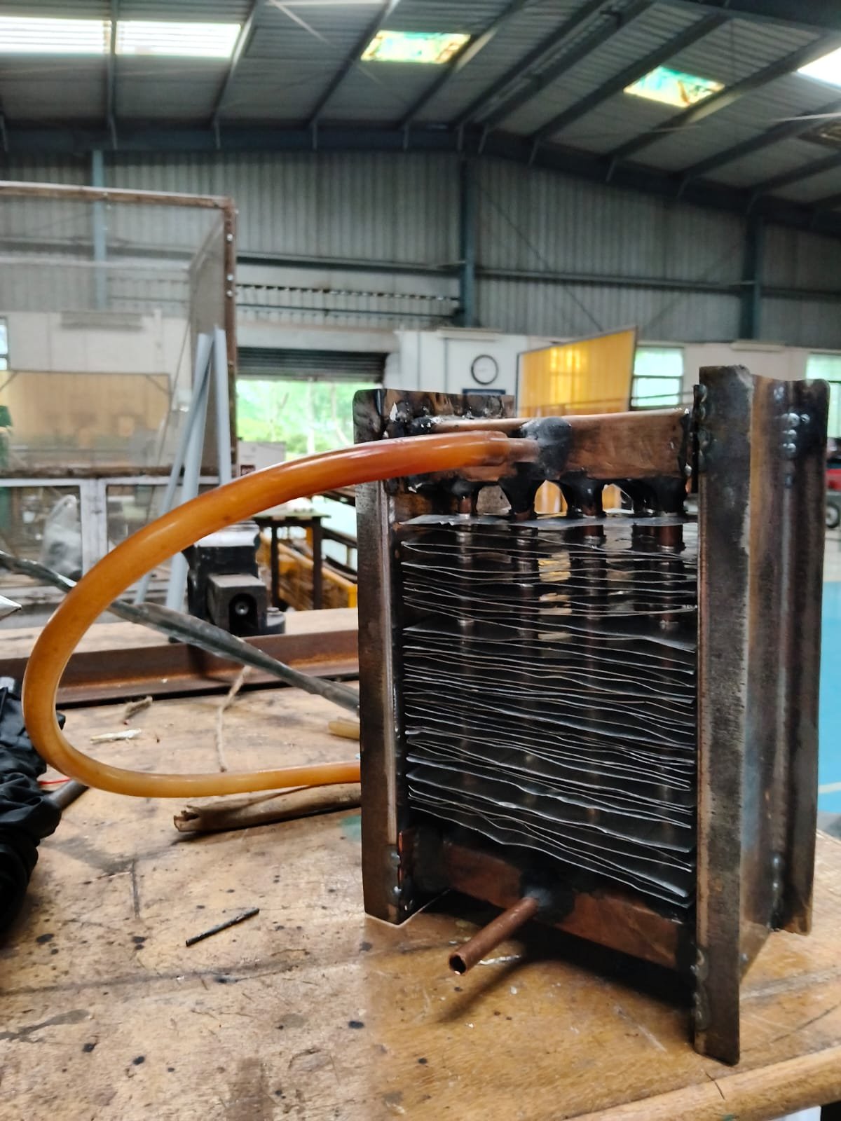
Final Status
- The radiator assembly was completed.
- All leakage tests are conducted.
- The leakages are negligible.
- The radiator will be ready for performance evaluation.
Week 4
Fan Installation
- Mounted the axial fan of (90 cfm) on the heat exchanger casing.
- Secured the fan with proper fastening by metal sheet casing.
- Prepared the system for forced-air testing.
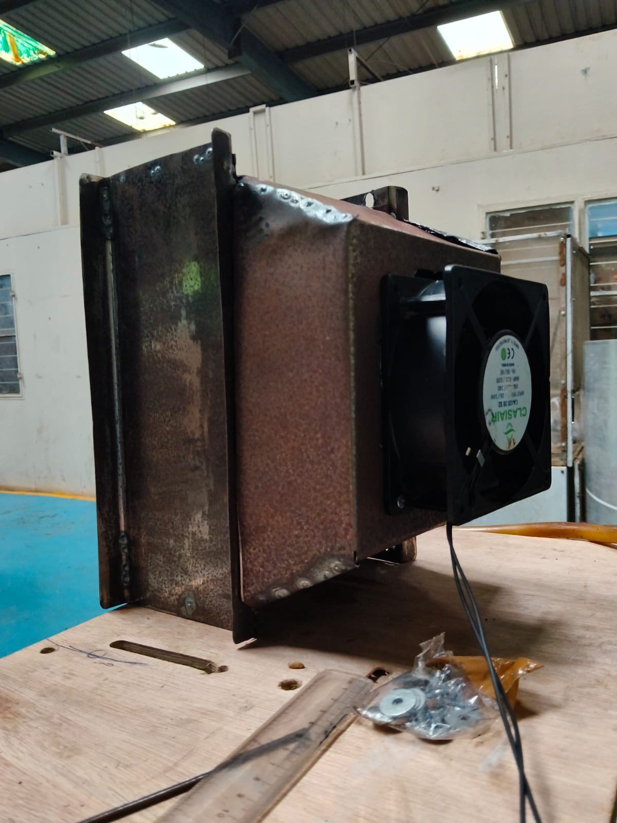
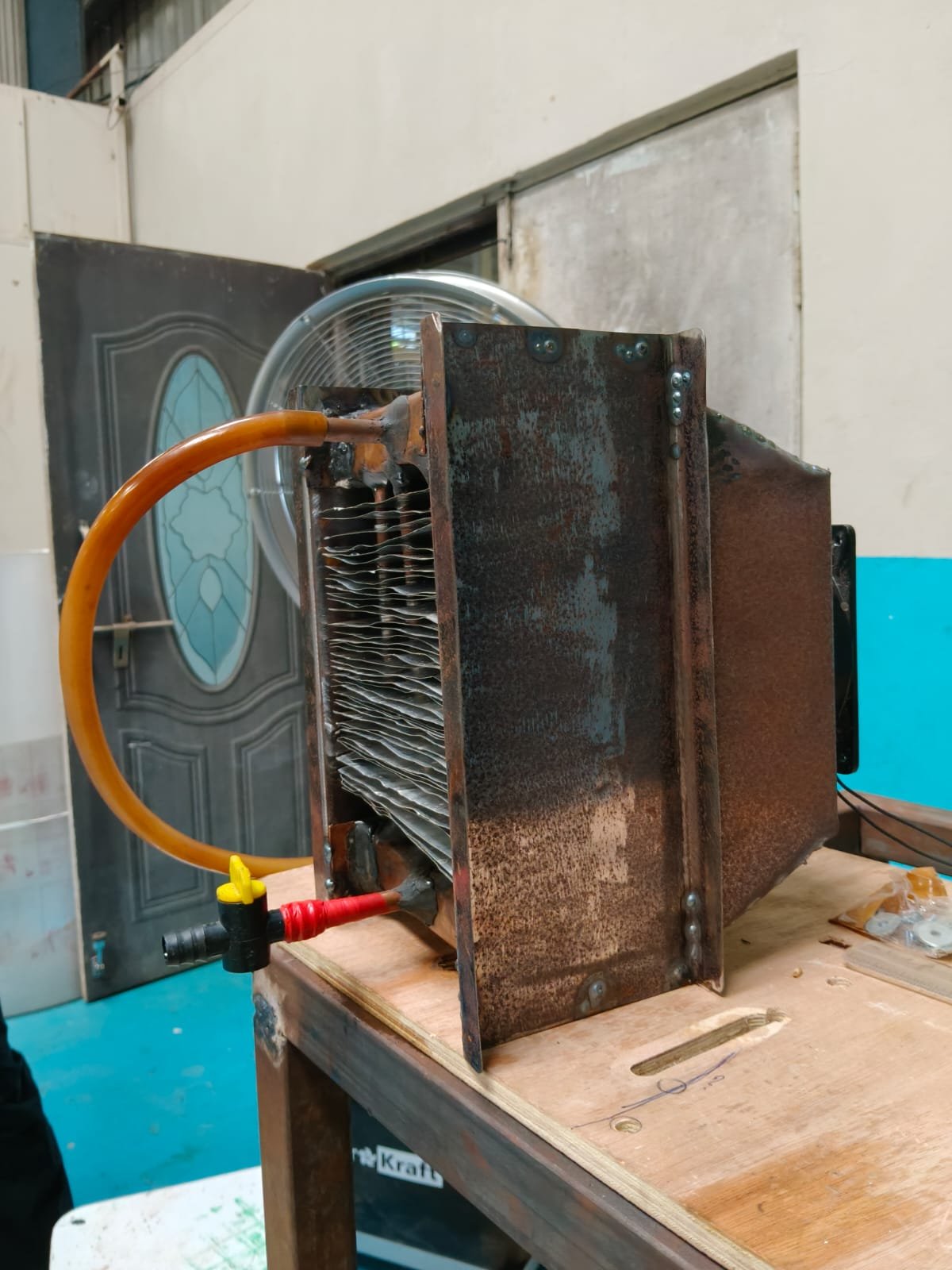
Heat Exchanger Assembly completed
- Completed the fabrication of the cross-flow heat exchanger.
- Connected the water inlet and outlet pipes.
- Connection of the fan(90 cfm) is done.
- Checked the overall assembly and structural alignment.
Performance Testing
- Conducted the initial performance test using hot water of (85 °c) circulation.
- Measured the inlet and outlet water temperatures and air outlet temperature.
- Observed stable operation and recorded experimental data for heat transfer performance and system capacity evaluation:-
Parameters and values
Hot Water Inlet Temperature
85°C
Hot Water Outlet Temperature
70°C
Air Inlet Temperature
26°C
Air Outlet Temperature
35°C
Maximum Air Velocity
3.3 m/s
WORKING ON PROJECT (SOLAR DRYER)
WEEK 1 (from 02/09/26 to 06/09/26)
1. Project Discussion and Aim:
During the initial discussion with Dixit Sir, it was decided to develop a system to improve the efficiency of the solar drying process. The system will use solar energy during sunny conditions and provide an alternative heating method when sunlight is not available.
2. Alternative Heating System:
For cloudy weather or low-sunlight conditions, a commercial radiator with hot-water circulation and a fan will be used to produce hot air inside the dryer. This will help maintain the drying process even without direct sunlight.
PREPARATION OF HOT WATER TANK FOR RADIATOR
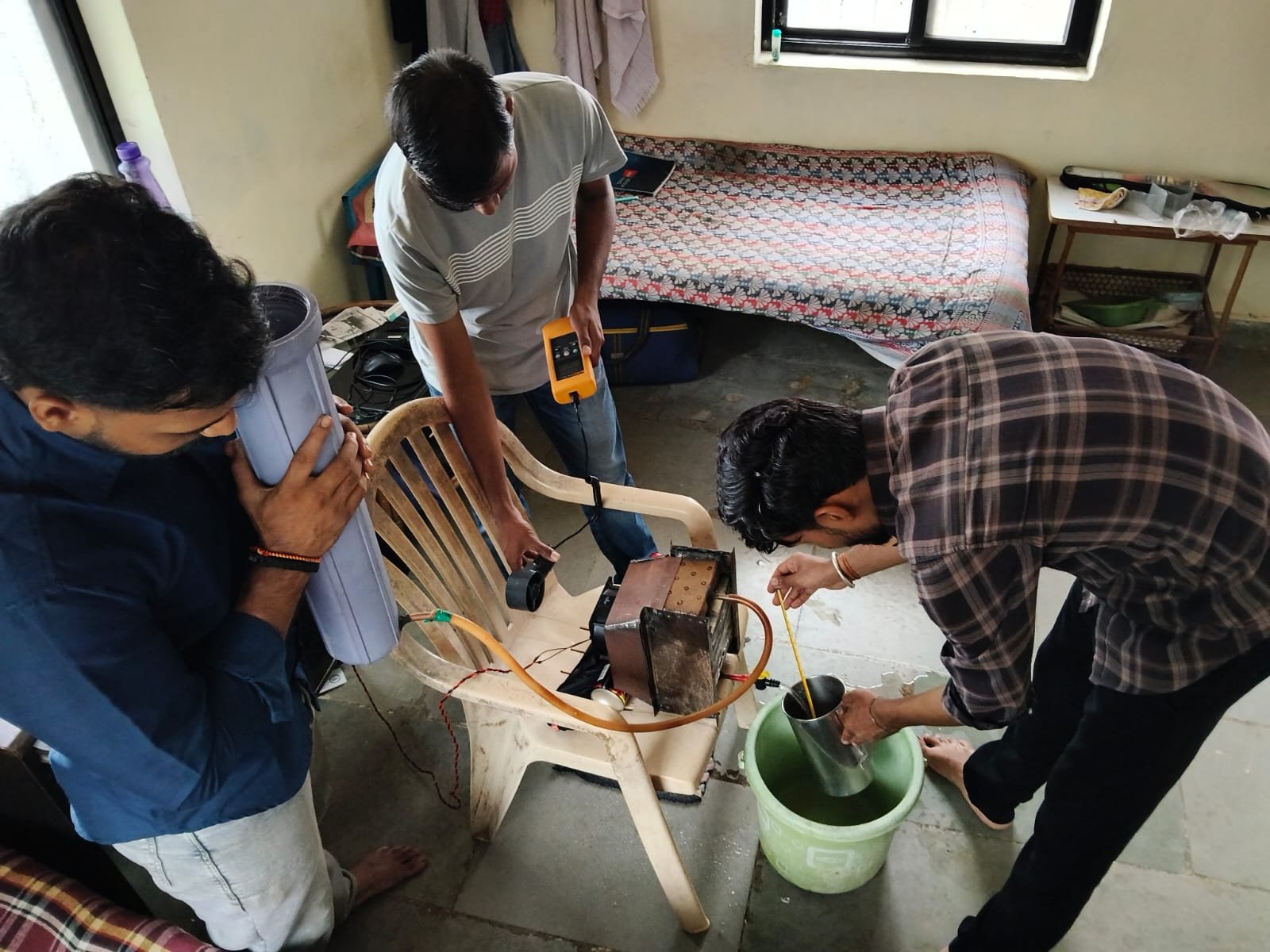
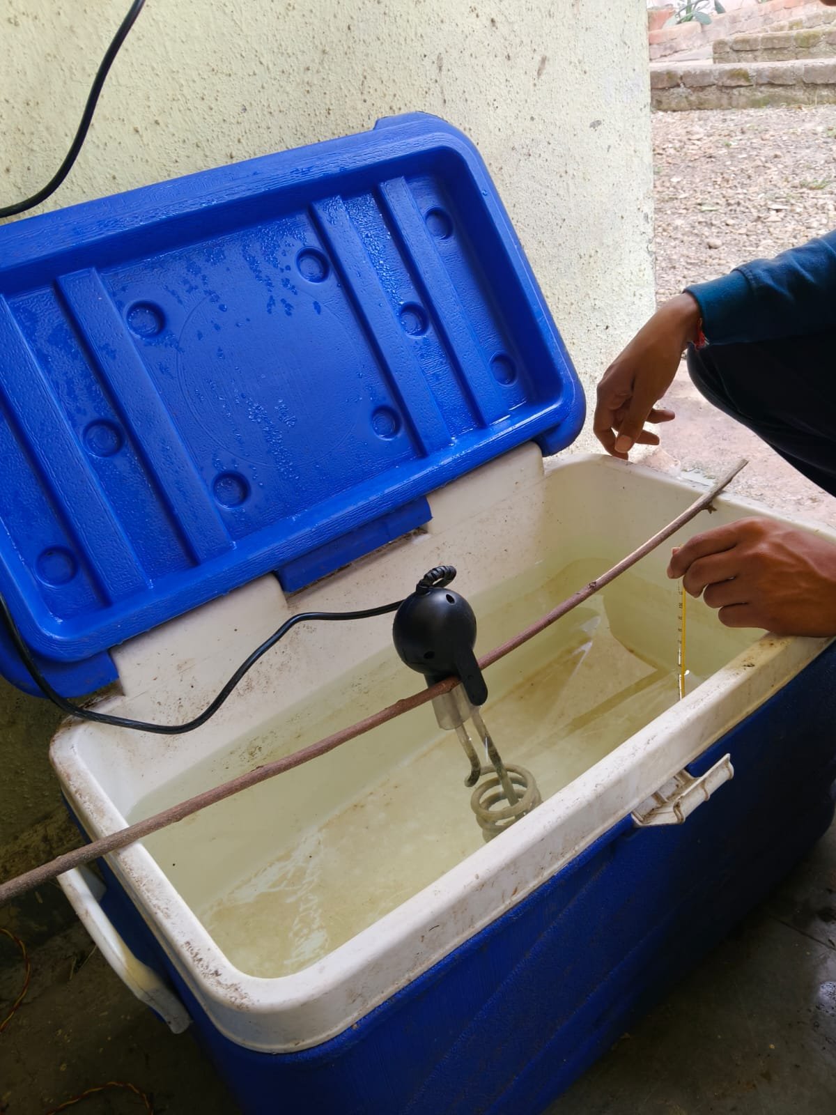
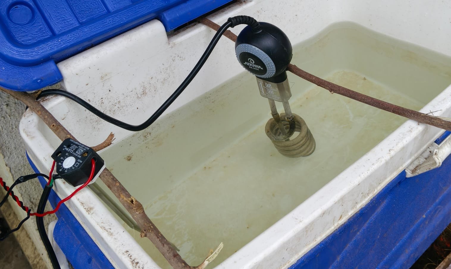
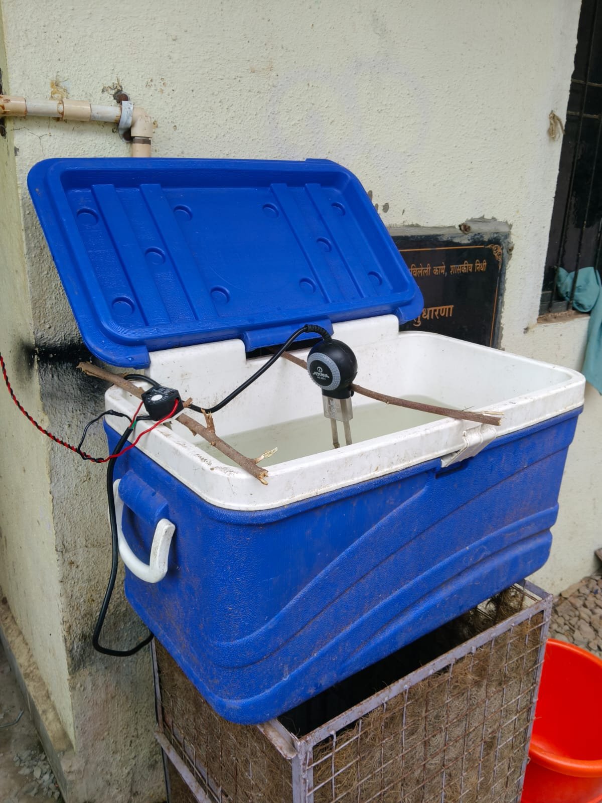
- Water tank of capacity (50 litres) is taken.
- Immersion rod of capacity (2000w) is taken for water heating.
- The required temperature of water which is reqired for our system is 60 degree celsius.
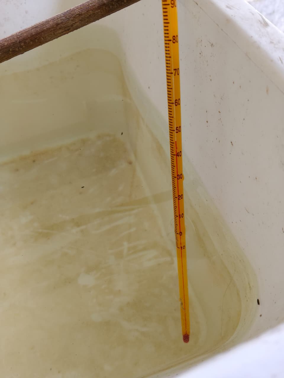
- The temperature measurement test is taken (manually) to determind the required time to achieve the required temperature.
- Temperature measurement test:-
- Quantity of water taken – 20lits.
- Glass thermometer
Result:-
Temperature(*c) Time(min.)
32 0
40 7.20
50 22.16
60 36.42
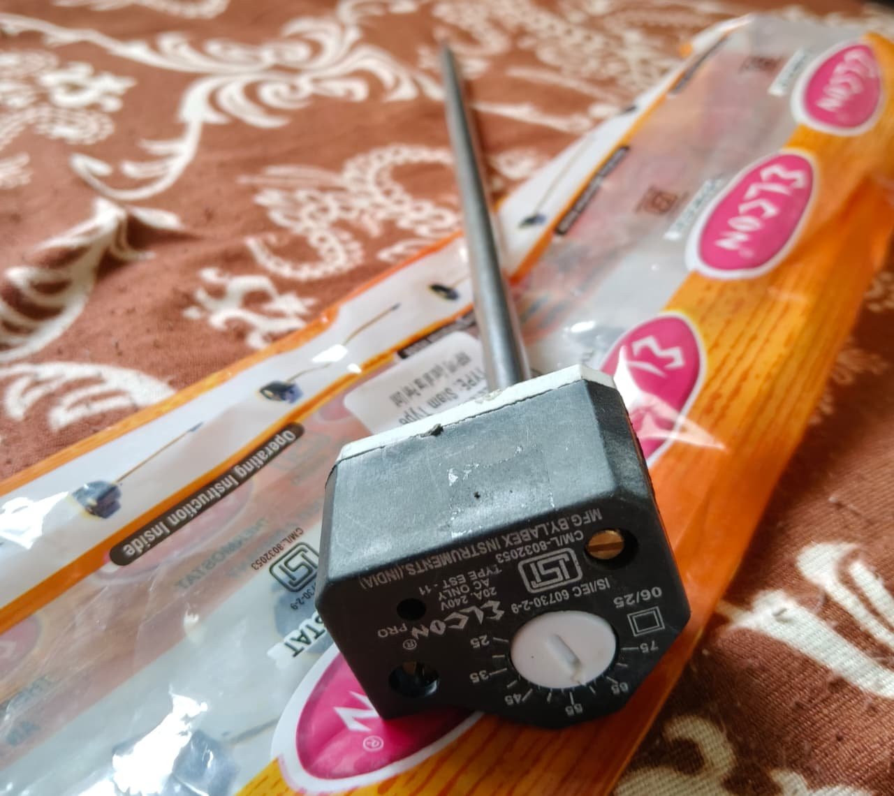
CYCLIC TIMER IS ADDED
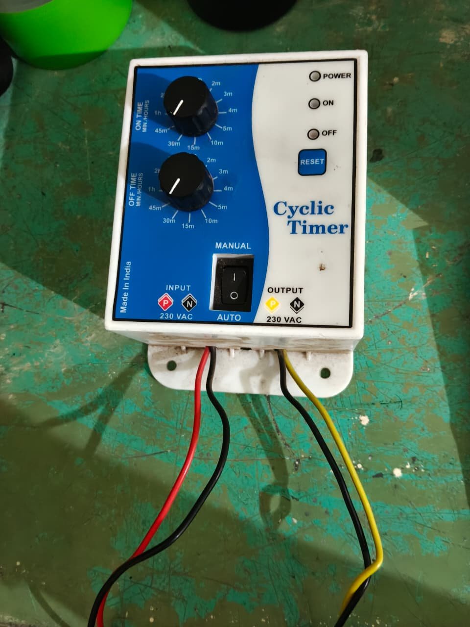
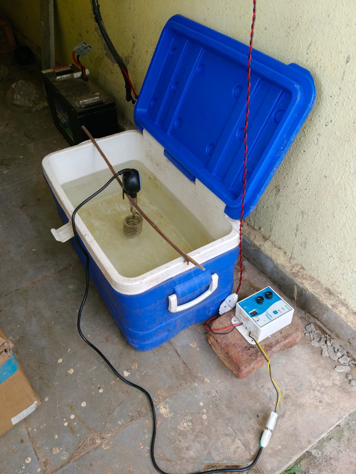
- A cyclic timer is added to the system to automatically switch the water heating rod ON and OFF.
week 2 (from 07/09/26 to 13/09/26)
Discussion and Project Decision:
- During the discussion with Dixit Sir last week, it was decided to purchase a commercial radiator for the solar dryer project.
- The main purpose was to use a ready-made radiator instead of fabricating a new radiator and to study its performance under controlled conditions.
- Also it is decided to change the cyclic timer with thermostat of(230v).
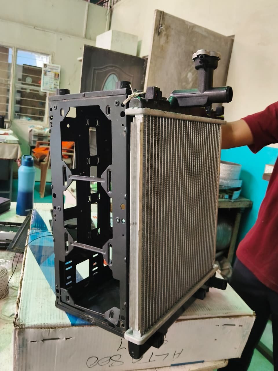
- Radiator’s specifications:-
| Parameter | Specification |
|---|---|
| Radiator type | Cross-flow |
| Core height | 350 mm |
| Core width | 300 mm |
| Core depth | ~16–26 mm |
| Tube count | 38 tubes |
| Tube outer diameter | 9.66 mm |
| Tube inner diameter | 8.73 mm |
| Fin count | 177 |
| Fin length | 13 mm |
| Fin thickness | 1 mm |
| Material | Aluminium core |

Commercial Radiator Procurement and Assembly:
- After the discussion, the commercial radiator was purchased and prepared for integration into the experimental system.
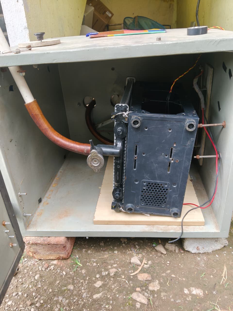
- The radiator was combined with an old CPU cabinet/body to provide a proper supporting structure and to make it easier to mount the radiator and fan assembly.
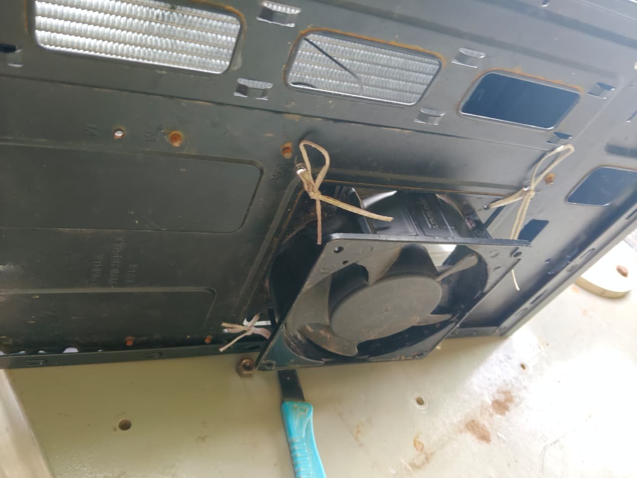
- Fan Integration:
A 90 CFM fan, which was previously used in our cross-flow radiator project, was integrated behind the commercial radiator. - The arrangement was designed so that the fan could force air through the radiator and improve heat transfer from the hot water to the air.
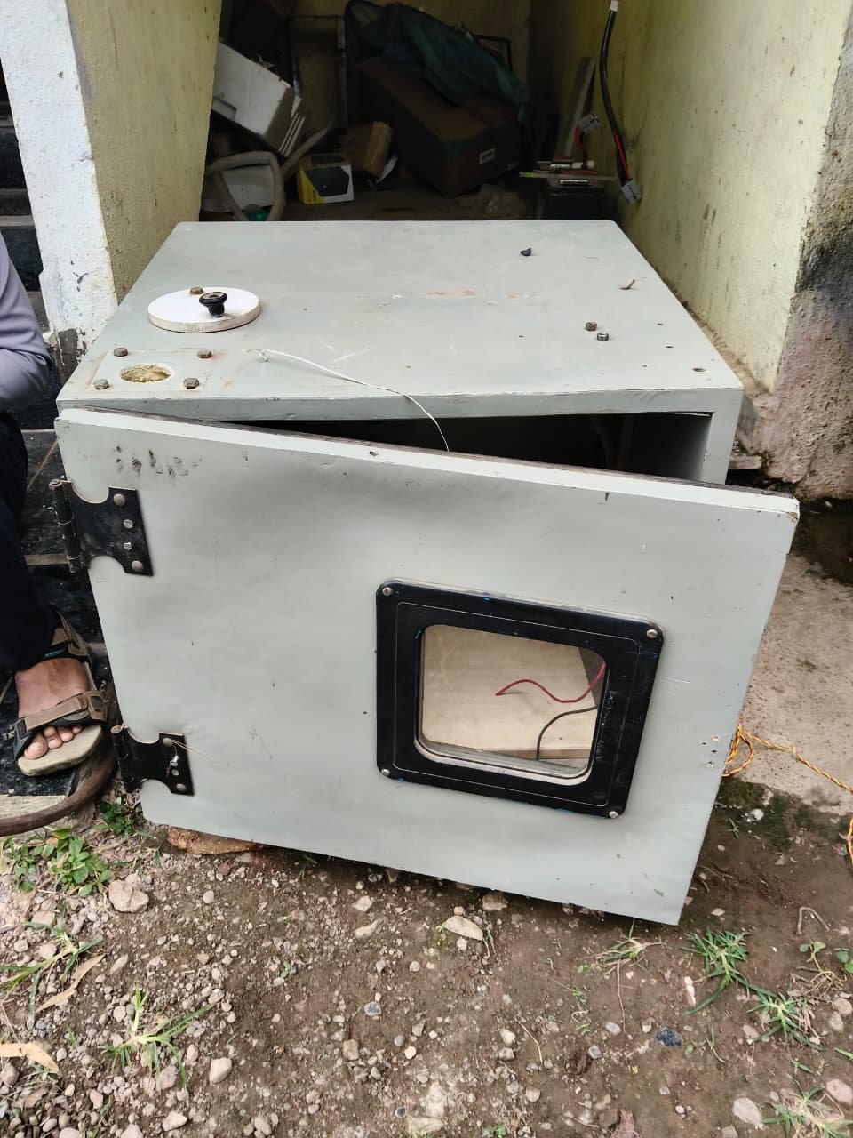
- Oven-Based Experimental Setup:
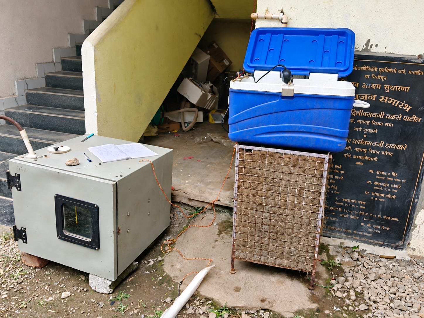
For testing, an oven/closed chamber of approximately 50 cm height 55 cm width 60 cm length was selected. The radiator and fan assembly were fitted inside the oven to study the heat transfer performance in a confined space.
oven-based experiment:-
- Testing Without Fan:-
The first experiment was planned with the fan switched OFF. Hot water was circulated through the radiator, and the temperature change inside the closed oven was observed. This test was intended to understand the natural heat transfer performance of the radiator without forced airflow. - Testing With Fan:-
A second experiment was performed with the 90 CFM fan switched ON. Hot water was again circulated through the radiator, while the fan forced air through the radiator. The results can be compared with the fan-OFF condition to determine the improvement in heat transfer and temperature rise inside the oven. - Water Heating and Temperature Control:-
The previously prepared 50 L water tank was integrated with the system. The tank was equipped with an immersion heating rod and thermostat to heat the water and maintain the required temperature before supplying it to the radiator.
Overall Experimental Objective:-
The main objective of these experiments was to compare the performance of the commercial radiator with and without forced airflow inside a closed chamber. The observations will help in selecting the suitable operating conditions and finalizing the radiator–fan arrangement for integration with the solar dryer.
| Parameter | Fan OFF | Fan ON |
|---|---|---|
| Initial water temperature | 22.5°C | 22.5°C |
| Water heating time | 1 hour | 1 hour |
| Water inlet temperature | 60°C | 60°C |
| Water outlet temperature | 48°C | 45°C |
| Ambient air temperature | 24°C | 24°C |
| Final air temperature | 27°C | 38°C |
| Test duration | 2 min 17 sec | 2 min 17 sec |
| Maximum air velocity | 3.3 m/s | 3.3 m/s |
| Water temperature drop | 12°C | 15°C |
| Air temperature rise | 3°C | 14°C |
calculations (for system efficiency)
Formula
Where:
- Flow rate = 13 L/min
- Water density approximately 1 kg/L
-
1. Fan OFF
Water:
- Inlet = 60°C
- Outlet = 48°C
- Temperature drop = 12°C
Therefore,
So, based on 13 L/min, the calculated heat transfer from the water is approx 10.88 kW.
Your air temperature increased from 24°C to 27°C.
Temperature effectiveness:
2. Fan ON
Water:
- Inlet = 60°C
- Outlet = 45°C
- Temperature drop = 15°C
So, based on 13 L/min, the calculated heat transfer from the water is ≈13.61 kW.
Air temperature:
- Initial = 24°C
- Final = 38°C
- Air temperature rise = 14°C
Temperature effectiveness:
| Parameter | Fan OFF | Fan ON |
|---|---|---|
| Water flow used | 13 L/min | 13 L/min |
| Water inlet | 60°C | 60°C |
| Water outlet | 48°C | 45°C |
| Water ΔT | 12°C | 15°C |
| Calculated heat transfer | 10.88 kW | 13.61 kW |
| Air inlet | 24°C | 24°C |
| Air outlet | 27°C | 38°C |
| Air ΔT | 3°C | 14°C |
| Temperature effectiveness | 8.33% | 38.89% |
These all calculations are on the basis of rated flow rate of water of pump which is 13 lit/min.
After the actual clculation of the flow rate of water we determine the acutal heat transfer rate of the system.
week 03 (14/09/26 to 20/09/26)
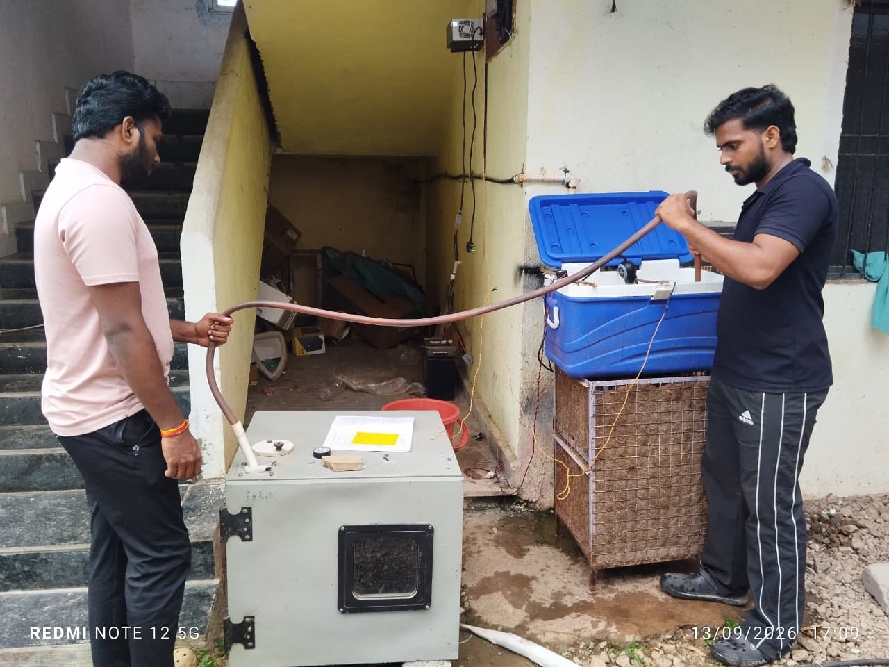
preparation of close loop system
- The preparation of the Close Loop system is done.
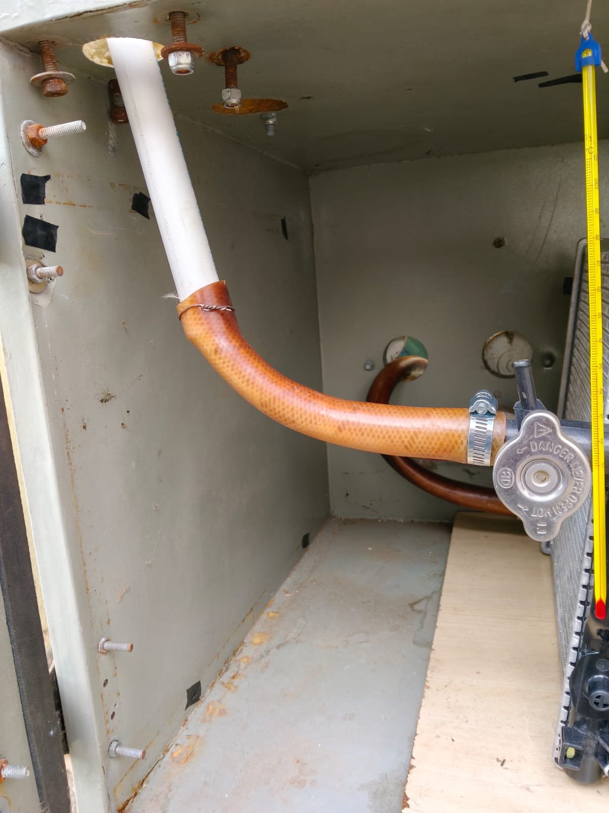
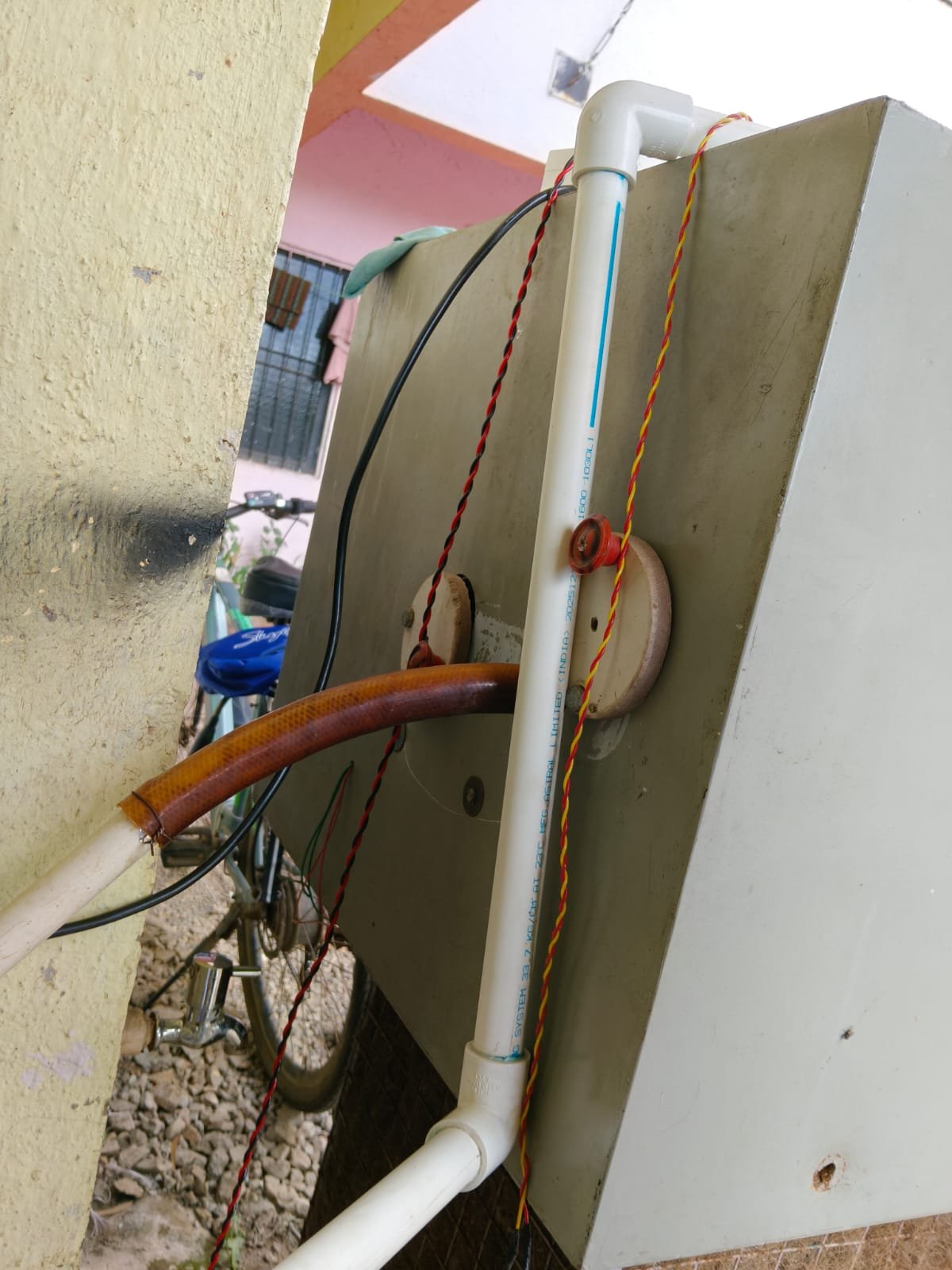
- we decided to put the oven is above the water tank at a distance of 50 cm from centre of the radiator inlet to the top of water table in tank.
- The pvc pipes of 3/4 inches with L bow and jointer are used.
- Normal submersible cooler pump of flow rate (13 L/m) is used for the system.
- The Testing with of the system is decided to continue the testing is for 1 hr to achieve the temperature at 60•c in oven cabinate.
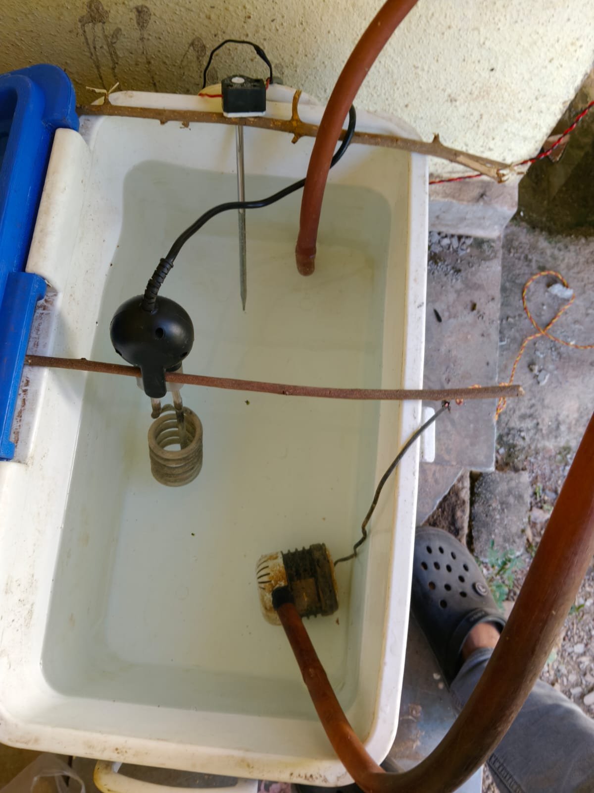
testing of radiator’s efficiency in close loop oven cabinate.
When fan is OFF :-
Water temperature
Initial – 60•c
Final – 47°c
Air temperature
Ambient – 29°c
Final – 44.5°c
After 44.5°c the temperature is constant.
When Fan is ON :-
Water temperature
Initial – 60°c
Final – 45°c
Air temperature
Ambient – 29°c
Final – 58.5°c
Fan air flow rate – 3.3m/s
After 1hrs the temperature is constant at 58.5°c
calculation of system efficiency.
Water flow rate: 13 L/min
Water density = 1 kg/L; specific heat, Cp = 4.186 kJ/kg·°C.
1. Water Mass Flow Rate
m■ = 13 ÷ 60 = 0.2167 kg/s
2. Fan OFF
Water inlet = 60°C
Water outlet = 47°C
Air inlet = 29°C
Air outlet = 44.5°C
Water temperature drop: ∆T = 60 − 47 = 13°C
Heat transfer:
Q = m■ × Cp × ∆T
Q = 0.2167 × 4.186 × 13 = 11.8 kW
Temperature effectiveness:
ε = [(44.5 − 29) / (60 − 29)] × 100 = 50.0%
3. Fan ON
Water inlet = 60°C
Water outlet = 45°C
Air inlet = 29°C
Air outlet = 58.5°C
Air velocity = 3.3 m/s
Air temperature became constant at 58.5°C after about 1 hour.
Water temperature drop: ∆T = 60 − 45 = 15°C
Heat transfer:
Q = 0.2167 × 4.186 × 15 = 13.6 kW
Temperature effectiveness:
ε = [(58.5 − 29) / (60 − 29)] × 100 = 95.2%
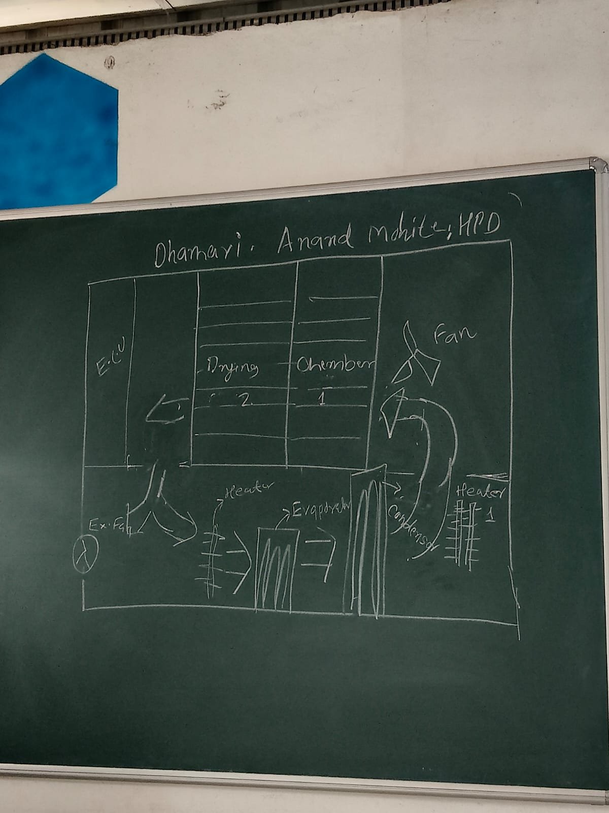
Study of Heat Pump Dryer System (ANAND MOHITE, from DHAMARI)
- During this week, the heat pump dryer system was studied with the help of the given system diagram.
- The major components such as the fan, condenser, evaporator, heaters, exhaust fan and drying chambers were identified.
- The airflow arrangement and working principle of the dryer were studied.
- It was understood that the fan circulates air through the heating and heat-pump sections before supplying hot air to the drying chamber.
- The hot air removes moisture from the material placed inside the chamber. The moist air is then passed through the evaporator for dehumidification and is reheated for further circulation.
- The role of the condenser, evaporator and heaters in maintaining the required drying conditions was also studied.
- The study helped in understanding the air circulation, heating, dehumidification and drying process of the heat pump dryer.
- Outcome:
The basic components, airflow path and working principle of the heat pump dryer were studied and understood.
week 4 (from 21/09/26 to 26/09/26
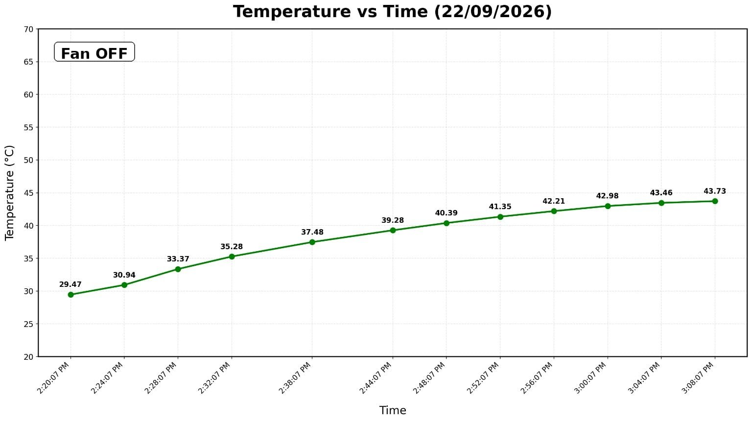
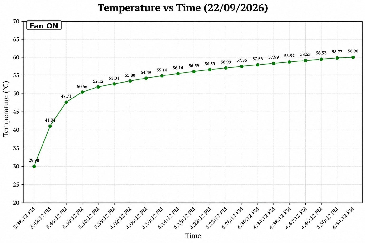
Data Logger Installation and Temperature Monitoring
- A temperature data logger was installed in the heating system to record temperature changes during the experiment.
- The data logger was used to monitor the temperature variation with respect to time.
- The temperature sensor/probe was placed inside the drying chamber/airflow region to measure the hot-air temperature.
- Temperature readings were recorded continuously during the testing of the system.
- The system was tested under different operating conditions, such as fan OFF and fan ON.
- The recorded data can be used to prepare a temperature vs. time graph.
- The data logger helps to identify the heating rate, maximum temperature, and temperature stabilization time.
- The recorded temperature data can also be used to compare the performance of the radiator system under different operating conditions.
- Continuous data recording reduces the need for manual temperature readings and improves the accuracy and consistency of the experiment.
- The data obtained from the logger will be useful for performance evaluation and further analysis of the drying system.
Temperature vs Time chart (by readings of datalogger)
cacluation of the losses from the pump inlet to radiator inlet.
- After discussion with Dixit Sir, we discussed that we need to determine the actual water flow rate through the system.
- It was decided to experimentally measure the water collected over a known time period and calculate the actual flow rate.
- Measurement of actual water flow rate
During the experiment, 1 litre of water was collected in 14 seconds. - The calculated actual flow rate was:
4.29 L/min
0.0715 kg/s mass flow rate. - Measurement of temperature drop before radiator inlet
- The water temperature was observed to decrease from 60°C to 58°C before reaching the radiator.
- Therefore, the temperature drop in the section between the pump/system and radiator inlet was 2°C.
- Calculation of heat loss
Using the measured mass flow rate and specific heat of water, the heat loss was calculated.
Calculated heat-loss rate: ≈ 598.5 W ≈ 599 W.
- This indicates that approximately 599 J of thermal energy is lost per second in the section corresponding to the measured 60°C → 58°C temperature drop.
- Energy-loss calculation
- Heat loss per second :599 J
- Heat loss per minute: 35,940 J
- Heat loss per hour: 2.1564 MJ
- Equivalent energy loss: 0.599 kWh/hour ≈ 0.599 unit/hour.
calculation of actual heat transfer rate of the system with by using actual flow rate of water in radiator outlet.
| Parameter | Fan OFF | Fan ON |
|---|---|---|
| Water flow | 4.29 L/min | 4.29 L/min |
| Water inlet | 60°C | 60°C |
| Water outlet | 47°C | 45°C |
| Water ΔT | 13°C | 15°C |
| Air inlet | 29°C | 29°C |
| Air outlet | 44.5°C | 58.5°C |
| Air velocity | — | 3.3 m/s |
Water-Side Heat Transfer Rate
Actual water flow rate = 4.29 L/min
Mass flow rate: mnw = 4.29/60 = 0.0715 kg/s
Specific heat of water: Cp,w = 4.186 kJ/kg·K
Equation: Q = mn × Cp × ∆T
Fan OFF
∆T = 60 − 47 = 13°C
Q = 0.0715 × 4.186 × 13 = 3.89 kW
Fan ON
∆T = 60 − 45 = 15°C
Q = 0.0715 × 4.186 × 15 = 4.49 kW
Increase in water-side heat transfer = 4.49 − 3.89 = 0.60 kW (600 W).
Percentage increase = (0.60/3.89) × 100 ≈ 15.4%.
Air-Side Heat Transfer Rate
For the fan-ON condition, the calculation uses the blower’s rated air flow of 90 CFM.
90 CFM = 0.04248 m³/s
At about 29°C, air density ≈ 1.165 kg/m³
Air mass flow rate: mna = 0.04248 × 1.165 ≈ 0.0495 kg/s
Specific heat of air: Cp,a ≈ 1.005 kJ/kg·
Fan ON: ∆Ta = 58.5 − 29 = 29.5°C
Qair = 0.0495 × 1.005 × 29.5 ≈ 1.47 kW
| Heat Transfer Basis | Fan OFF | Fan ON |
|---|---|---|
| Water-side heat transfer | 3.89 kW | 4.49 kW |
| Air-side heat transfer | Not determined | ≈1.47 kW* |
| Water flow | 4.29 L/min | 4.29 L/min |
| Water ΔT | 13°C | 15°C |
| Air ΔT | 15.5°C | 29.5°C |
week 5 (from 27/09/26 to 04/10/26)
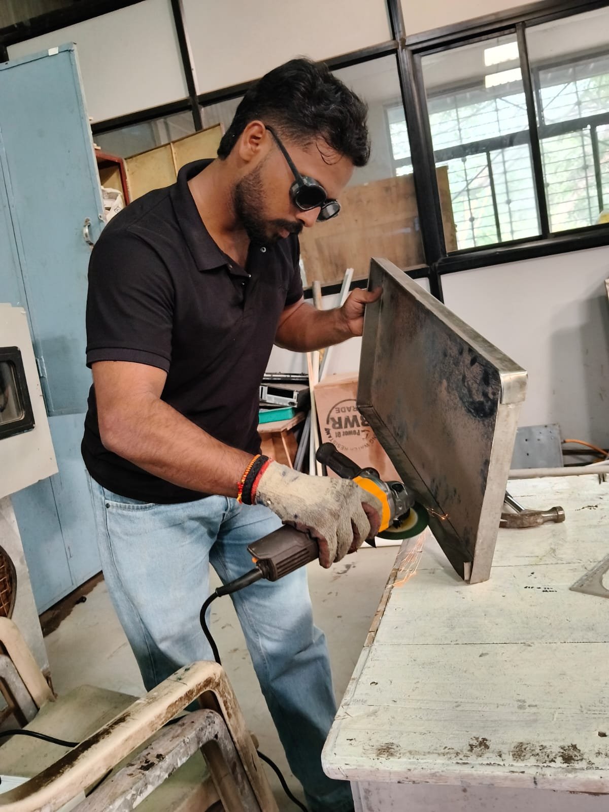
Tray Design and Fabrication
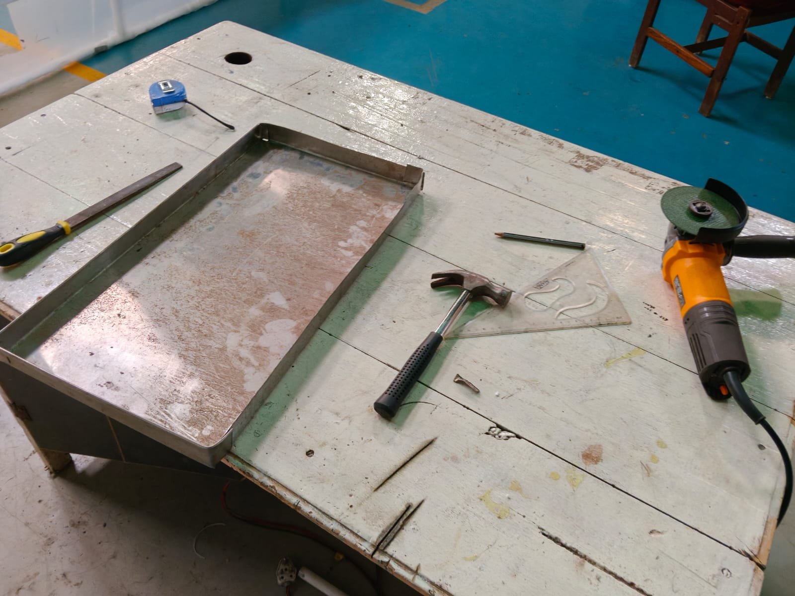
- The existing metal drying tray was further developed for use in the dryer.
- Grinding and finishing work was carried out on the tray/frame to improve its shape and fitting.
- The tray was checked for proper placement and handling inside the drying chamber.
- The existing solid tray surface was studied for modification to improve hot-air circulation.
- Tray dimensions.
| Parameter | Specification |
|---|---|
| Length | 52 cm |
| Width | 19 cm |
| Side Height | 3 cm |
| Material | Aluminium |
Tray Design and Testing
- The initially designed aluminium drying tray without perforation was fabricated and practically tested in the drying chamber.
- The tray was installed in the dryer to check its size, fitting, handling and drying arrangement.
- Practical testing was carried out using the selected drying material.
- Photographs and observations were recorded during the testing process.
- Based on the initial test results, the tray design was further reviewed for improvement in air circulation and drying performance.
- For the next stage, the tray will be modified into a perforated/mesh-bottom design to improve hot-air contact with the drying material.
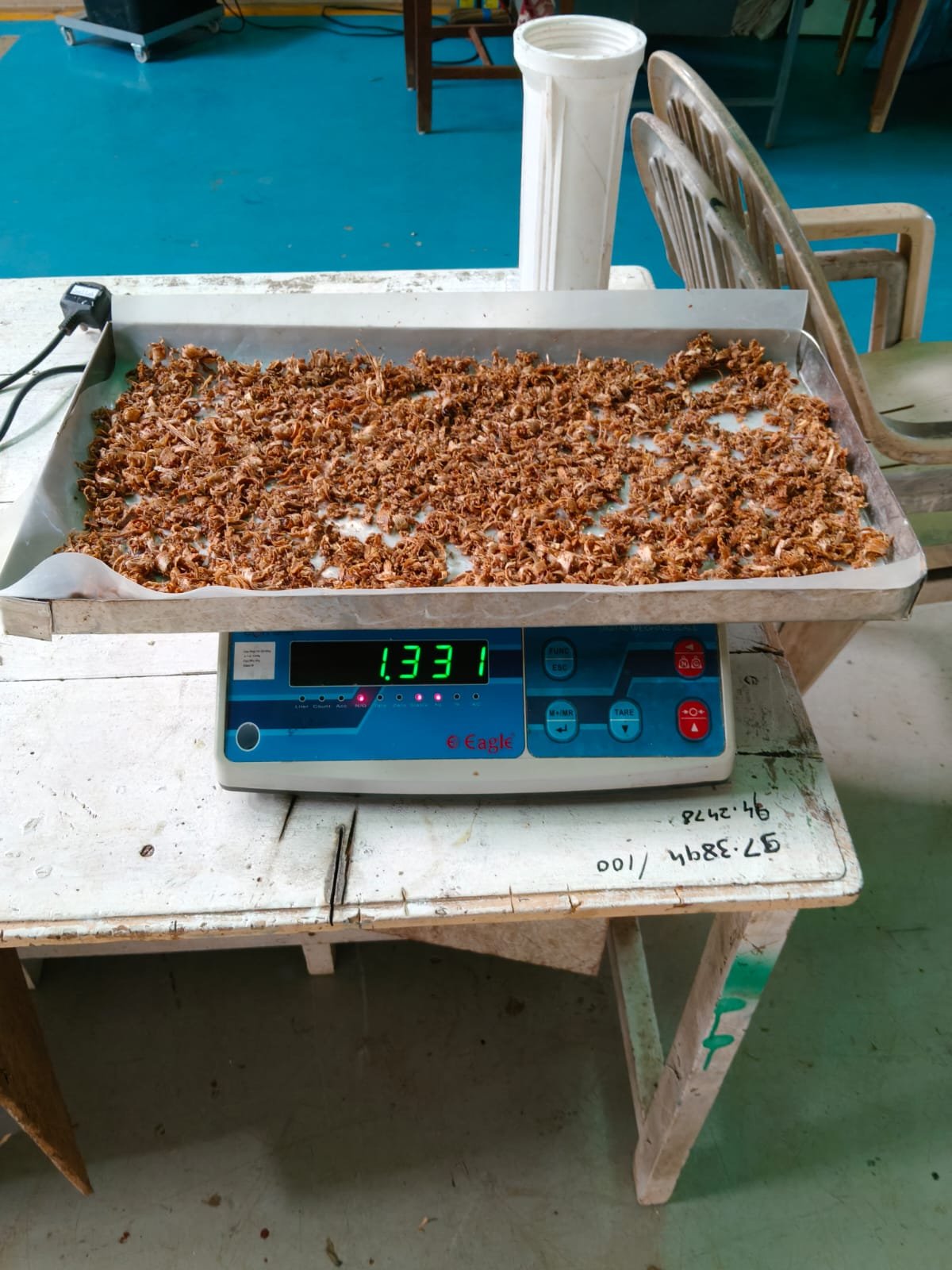
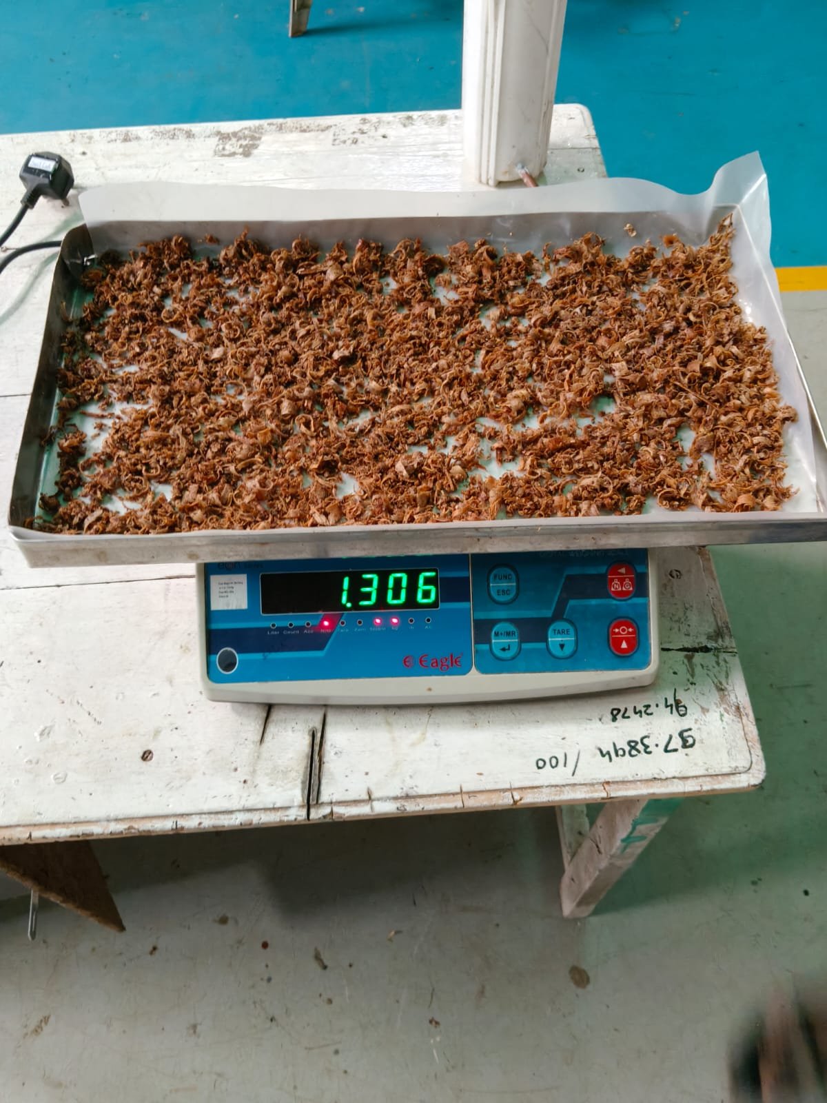
- After discussion with DIXIT SIR , i decide to perform a drying process by the saw dust in the designed aluminium tray.
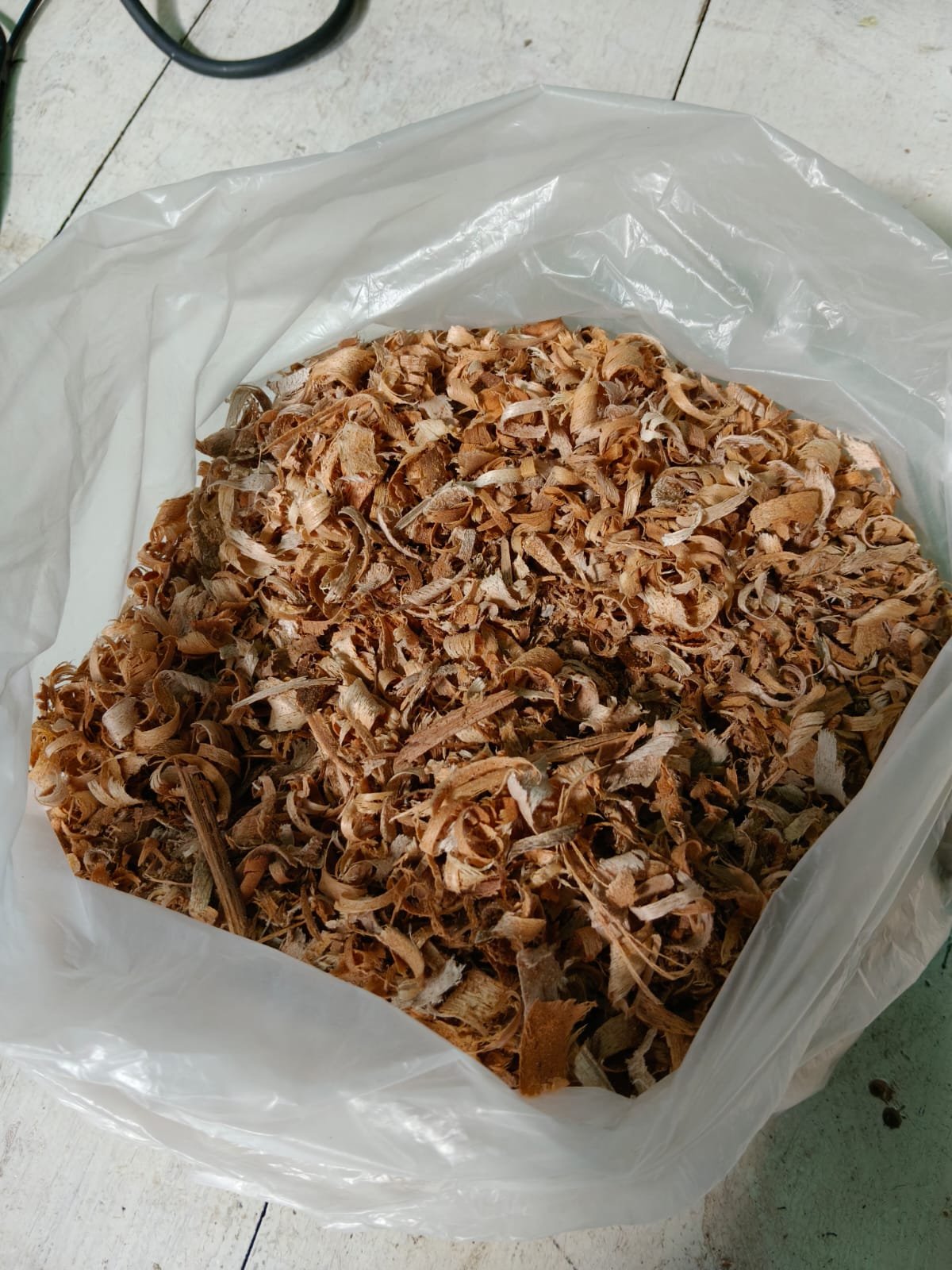
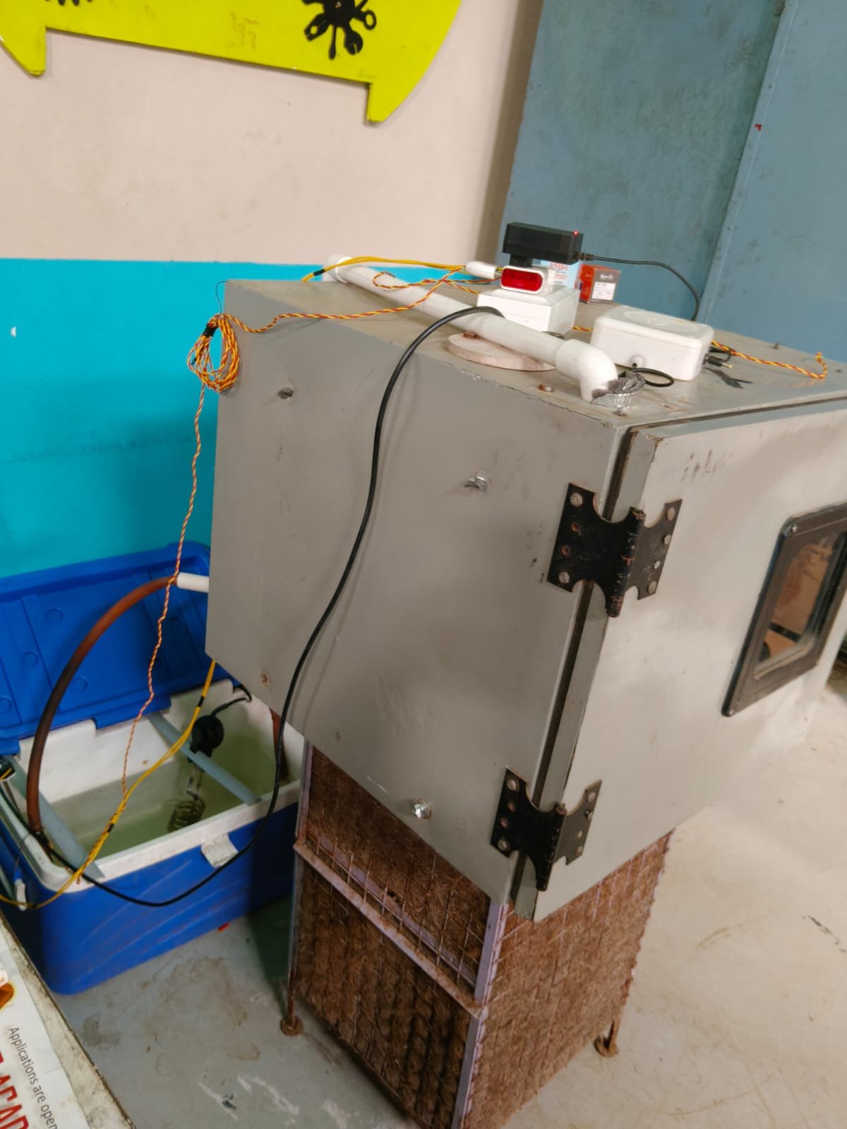
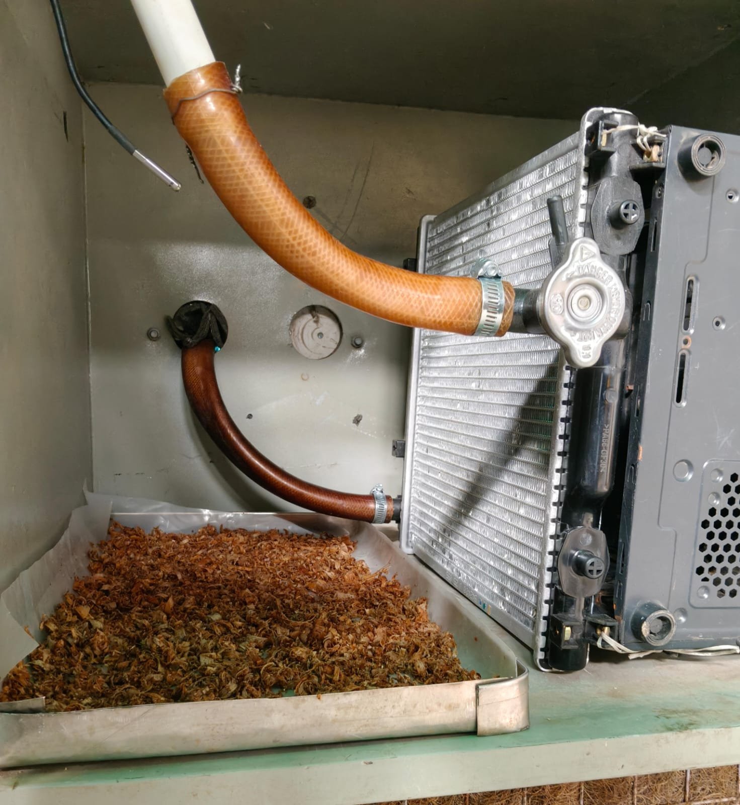
Saw dust drying calculation
| Parameter | Before drying | After 1 h |
|---|---|---|
| Total sample weight | 350 g | 315 g |
| Dry-solid weight | 77 g | 77 g |
| Water content | 273 g | 238 g |
| Water removed | — | 35 g |
| Drying time | 0 h | 1 h |
Weight Loss During Drying
Weight loss = Initial weight − Final weight
= 350 − 315
= 35 g
Percentage Weight Loss
Percentage weight loss = (Weight loss / Initial weight) × 100
= (35 / 350) × 100
= 10%
4. Drying Rate
Drying rate = Weight loss / Drying time
= 35 / 1
= 35 g/h
In minutes:
Drying rate = 35 / 60 = 0.583 g/min
Modification of tray
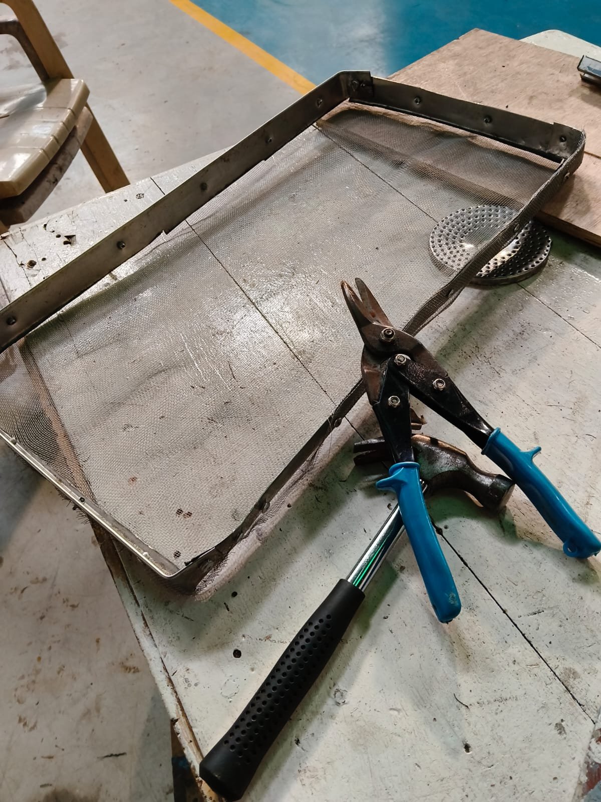
- The aluminium plan tray is to be modified into perforated mesh tray by wired mesh.
- The pop rivets are used to connect the wired mesh to the tray frame.
- The modification of the tray is necessary to incerase the air circulation of the tray in the oven cabinate.
- The perfored mess type tray is very beneficial for the good drying of the products like, saw dust, onion slices etc.