All you need to know about Solar Drying!
How does the solar dryer work?
Solar dryers are devices that use solar energy to dry substances, especially food.
Traditional method of sun drying food is to place food in the sun in the open. This is effective for small amounts of food as the area needed for sun drying increases with food quantity and since the food is placed in the open air, it is easily contaminated. Therefore, one major reason why sun drying is not easily performed with larger quantities of food is that the monitoring and overview of food becomes increasingly difficult.
In contrast to sun drying, the solar drying method uses indirect solar radiation. The principle of the solar drying technique is to collect solar energy by heating-up the air volume in solar collectors and conduct the hot air from the collector to an attached drying chamber. In this closed system, consisting of a solar collector and a drying chamber, without direct exposure to the environment, food can be dried more hygienically as there is no contamination of the products through rain, dust, insects, rodents or birds. The products are dried by the flow of hot air only. There is no direct impact of solar radiation (sunshine) on the product either. The solar energy produces hot air in the solar collectors. Increasing the temperature in a given volume of air decreases the relative air humidity and increases the water absorption capacity of the air. The use of this property of hot air for drying results in effective dehydration of the product.
Types of Solar Dryers
There are a variety of solar dryer designs. They can be primarily classified on the basis of the type of air flow generated in the drying chamber:
Natural convection dryers
These are solar dryers that use the natural vertical convection that occurs when air is heated. Generally, natural convection dryers are sized appropriately for on-farm use. The structure consists of three main components: a solar collector, a drying bin and a solar chimney. Natural convention dryers that are smaller in scale are basically wooden boxes with vents at the top and bottom. Food is placed on screened frames which slide into the boxes. A properly sized solar air heater with south-facing plastic glazing and a black metal absorber is connected to the bottom of the boxes. Air enters the bottom of the solar air heater and is heated by the black metal absorber. The warm air rises up past the food and out through the vents at the top.
Forced convection dryers
The convection is forced over the food through the use of a fan. In the case of forced convection dryers, the structure can be relatively similar. However, the forced convection dryer requires a power source for the fans to provide the air flow. The forced convection dryer doesn’t require an incline for the air flow however, the collector can be placed horizontally with the fan at one end and the drying bin at the other end. In addition, the forced convection dryer is less dependent on solar energy as it provides the air flow itself; this allows the design to work in weather conditions in which the natural convection dryer may not be viable.
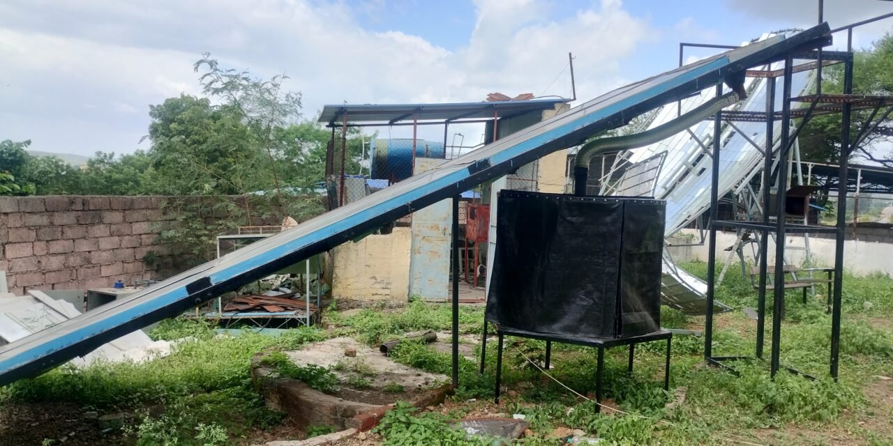
Introduction
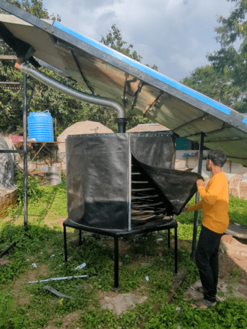
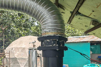
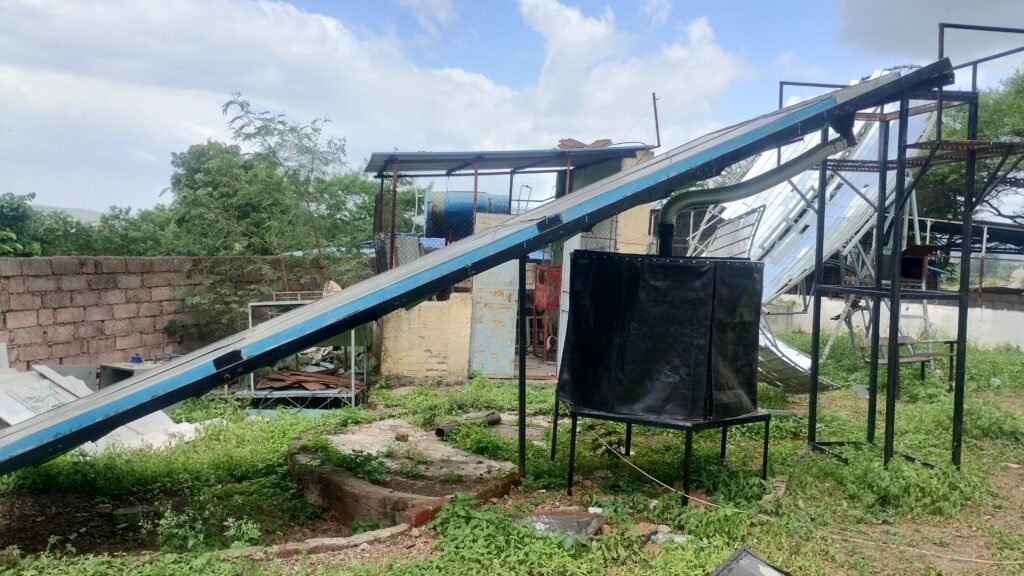
The Solar Dryer installed at Vigyan Ashram, Pabal is a Forced Convection Type Solar Dryer. It relies on a 12 sq m Glass Solar collector plate for Air Heating. The air rises upward into the air duct and is forced into the drying chamber with the help of an AC Exhaust fan. The dryer was not functional due to panel gaps in the drying chamber and ineffective air flow for dehydration. Our task was to improve upon the existing dryer by fixing its issues in air flow and making it fit for drying spices and vegetables.

September 01, 2024
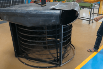
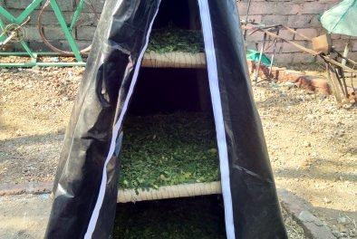
Creating doors for the drying chamber
The doors previously installed on the drying chamber allowed for panel gaps which affected the overall performance of the dryer. To avoid this we decided to go with strap doors which can be lifted to open and can be strapped back to seal the chamber. To build the doors to the drying chamber we decided to use a thick 500 GSM plastic sheet that extends down from all four sides of the frame. To ensure it stays in place and maintains an airtight seal, we attached loop-side of the hook and loop fastener strips to three sides of the plastic sheet: the right, left, and bottom edges. These strips are designed to adhere securely to the frame and allow for easy attachment and removal.
September 02, 2024
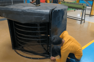
Installing doors on the drying chamber
The installation process involves positioning the plastic sheet so that it is sandwiched between the frame and the top cover of the structure. Once the strips on the plastic sheet are aligned with their counterparts on the frame, the sheet will be folded over itself at the edges. This folding action creates a snug fit and an airtight seal around the door area, preventing any air or moisture from escaping.
By using this method, we ensure that the door is not only secure and stable but also provides an effective barrier against the elements, enhancing the overall functionality of the dryer.
September 03, 2024
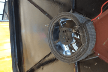
Installing Exhaust Fan
Next we installed an exhaust fan at the base of the drying chamber. The function of this exhaust fan is to suction out the humid air which has cooled down by evaporation of water from the vegetables.
We covered the exhaust fan with insulating foam and covered any remaining small gaps around the opening with a silicone-based sealant. This ensured that the fan was securely fixed and that no air or moisture could escape.

September 04, 2024
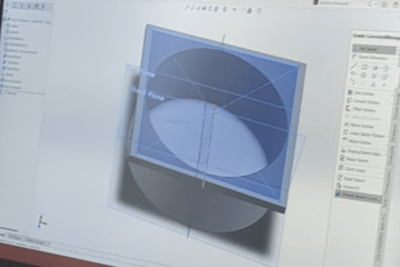
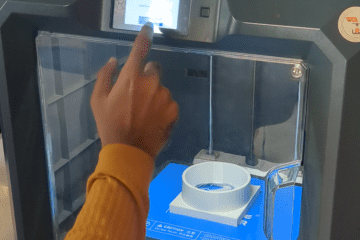
Creating a 3D Printed Intake Fan Adapter
Now we needed to ensure there was sufficient suction at inlet as well for the flow of hot air inside the drying chamber. For this purpose an intake fan is to be fitted on the inlet of the drying chamber. To securely fit the intake fan between the outlet of the hot air duct and the inlet of the drying chamber we designed and 3D printed an Adapter out of PLA resin which can be mounted at both ends of the fan and can be easily be fit between the duct and the pipe.
- The part was first drafted on the basis of the dimensions of the components in assembly.
- We then utilized Solidworks for Solid Modelling to get a .stl file of the part design.
- The .stl part design file was then processed over a slicing software.
- The sliced part design file was uploaded into the 3D printer to begin 3D printing the part.
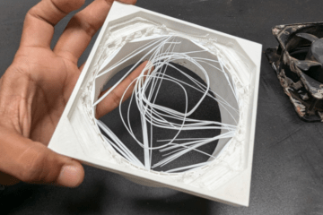
- After 3D printing the PLA resin part, uncured resin was carefully retouched to obtain the required finish.
- This took 2 consecutive days as each part need to be 3D printed individually for 6 hours and then finished by hand.
September 07, 2024
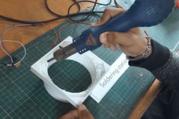
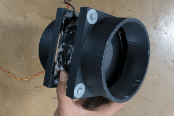
Installing the Intake Fan
Finally we installed the intake fan on the inlet. We drilled holes into the 3D printed adapters and carefully aligning the holes on each corners we fastened the adapter on to the intake fan. Then we installed the intake fan onto the inlet of the drying chamber.
September 08, 2024
Installing a New Inlet Duct
The previous dict pipe used for inlet into the drying chamber was made of a steel pipe and had caught rust over time, even after sanding the surface had trace amounts of rust which would later prove harmful for the dryer. We decided to install a new duct altogether instead. The duct is constructed of a flexible stainless steel pipe clamped by clamp rings screwed at both ends of the pipe making it airtight. The duct can easily come off by unscrewing for disassembly of drying chamber.
September 09, 2024
Assembly and Wiring
With all the individual components ready, I finally assembled the dryer at the site. Every part had been meticulously designed and fabricated. The parts were each screwed on each other and the mating was thoroughly checked for panel gaps and misalignments.
The gaps were inspected and carefully filled with a silicone based sealant to avoids any leakages. Wiring was done using a 0.5 sq mm insulated copper wire with switches.
A brief trial was conducted by turning on the intake and exhaust fans. The dryer seemed to be working well. When the intake fan was turned ON temperature rose steadily in the drying chamber and then dropped after exhaust fan was switched ON.
The project was a great learning experience for me and serves as an amazing introduction to the world of indirect solar drying. The next step in the development of this project would be to install an electronics system for temperature control. The system would automatically turn ON/OFF the fans as per the thermodynamic conditions inside the drying chamber.
September 13, 2024
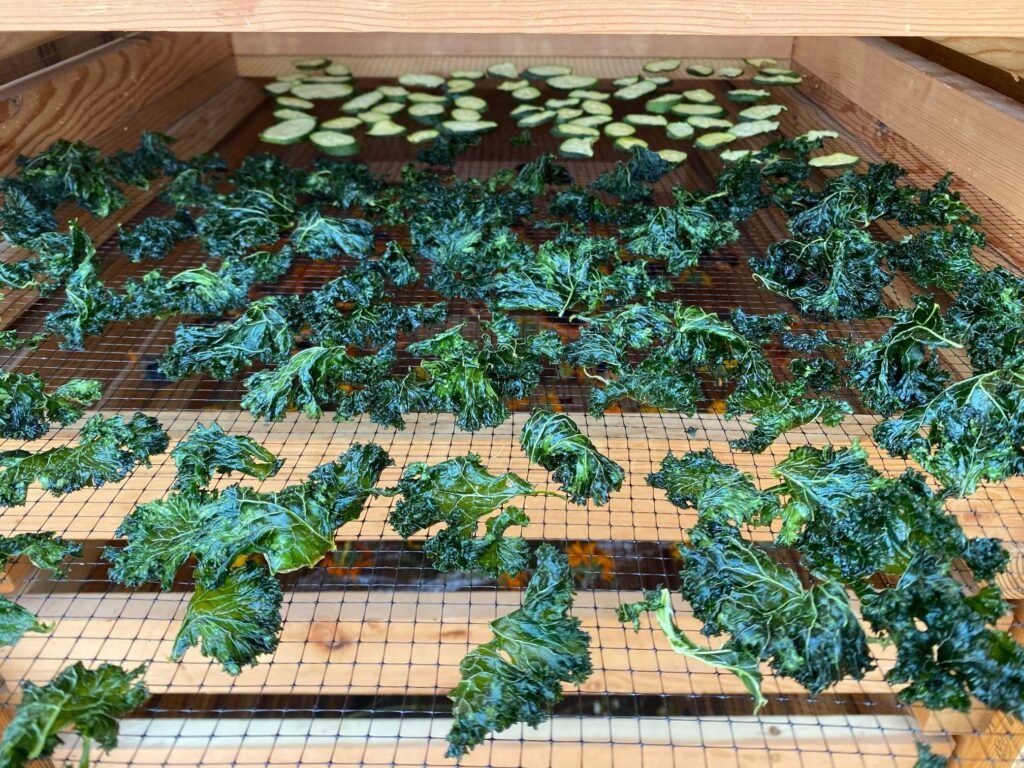
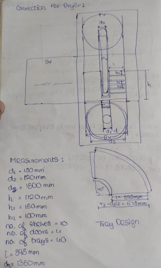
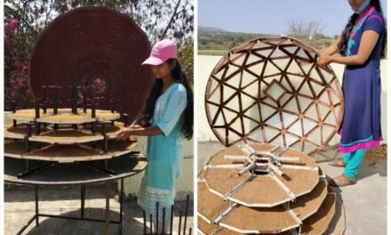
Design of Drying trays
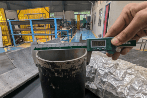
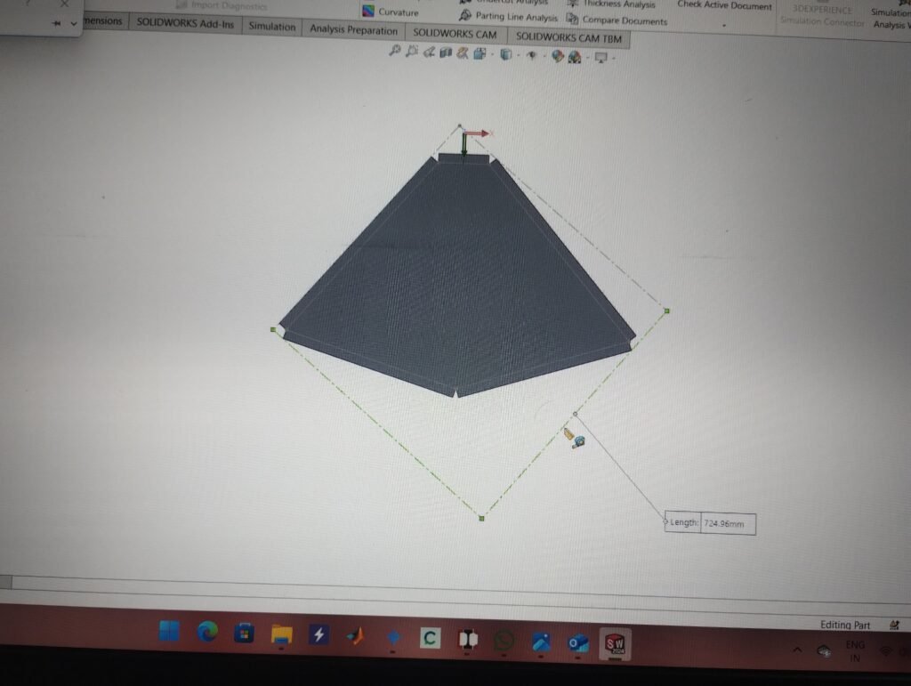
The drying trays for our Forced Convection Solar Dryer were designed to efficiently dry Moringa leaves, Turmeric, Ginger, etc. To determine the optimal dimensions, we carefully measured the dimensions of the drying chamber using a measuring tape and Vernier caliper.
These measurements were used to create a tentative design that incorporated factors such as surface area, depth of the tray and holes for airflow. We also considered the ergonomics of handling the drying trays during the design process.
September 14, 2024
Design for Manufacturing
After finalizing the drying tray design, we focused on the design for manufacturing. To ensure the trays were durable, safe, and cost-effective, we carefully selected SS 304, Galvanized Iron or Aluminum for the fabrication.
We also considered the type of perforated sheet to use. There are mainly three variation in hole size available in the market i.e. 2mm, 3mm and 4mm of hole sizes and three variations in hole types, i.e. standard, dimpled and mesh. We decided on using 3mm standard hole perforated sheets for our drying trays as 3mm holes were sufficient for air circulation while allowing for any food product to be easily stored without risking it falling between the trays.
September 15, 2024
Overcoming Manufacturing Limitations
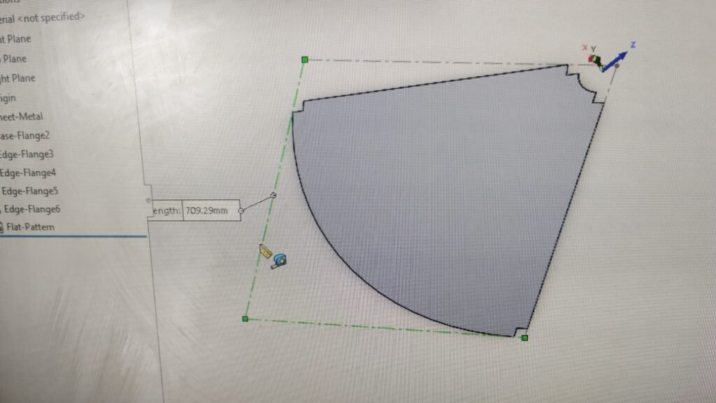
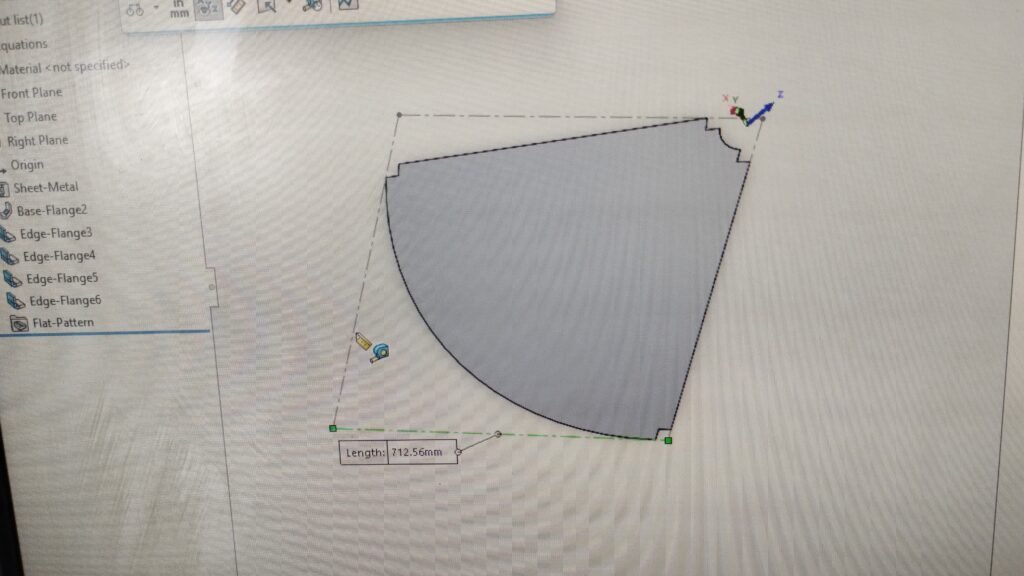
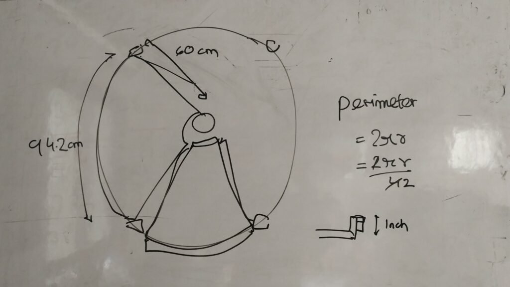
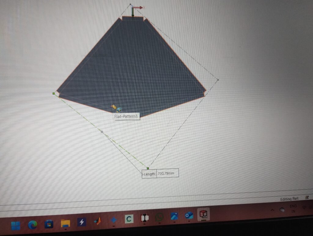
To facilitate the manufacturing process, we created a detailed CAD drawing of the sheet metal flat pattern. This drawing provided precise dimensions and specifications for the laser cutting and bending of the perforated sheets.
A major challenge that occurred during this was the inability of the bending machine used by the manufacturer to bend curved surfaces at 90 degrees. This was overcome by making required changes in design like opting for a lower polygon approach by converting the curved edge to two adjacent plane surfaces at an obtuse angle.
By collaborating with the manufacturer, we obtained a tentative quote for the manufacturing cost. The Manufacturer also provided us with a nesting diagram to utilize maximum available material.

September 30, 2024- October 07. 2024
Market Research
For manufacturing of the drying trays, I required perforated metal sheets. As discussed previously, I did Market research for the availability and cost of the materials. I used various sources for this initial research to contact the possible vendors. Following is the comparison chart of quotes provided by two of these vendors.
https://docs.google.com/spreadsheets/d/1zJUDkbPM3SbKrwRLE7y8URecXDOZNvNT/edit?usp=drive_link&ouid=105022313729015342047&rtpof=true&sd=true: Forced Convection Solar DryerOctober 09, 2024
Design of Experimental Setup
After a discussion regarding the budget for the fabrication of Drying Trays and the performance of the Dryer, we decided to initially fabricate and test drying trays out of polypropylene mesh to have an idea of the performance of the dryer. We decided to have a random arrangement of drying trays in the Drying chamber for the trial run with one tray in each of the 9 levels.
There had been a previous iteration of the drying trays for testing, five of which remained at the Vigyan Ashram scrapyard. Thus, the task at hand was to refurbish the five existing trays and fabricate four new trays. I divided my workload into distinct activities:
- Procuring existing trays
- Procuring materials for new trays
- Cutting and Grinding Metal Frames
- Providing Rust-resistant coating
- Assembly of Drying trays
October 11, 2024
Procuring existing trays
After searching through the scrapyard, I salvaged some old drying trays from the previous iteration of the dryer. These trays were made of HDPE sheets. The frame of these trays had been fabricated out of 20mm wide and 3mm thick Mild Steel angles. These frames had visible signs of rusting and had broken welds. The tray frames were disassembled by unscrewing the HDPE sheets and removing the broken welded joints.
October 14, 2024
Procuring materials for new trays
The materials needed for the fabrication of new trays include:
- Polypropylene Mesh
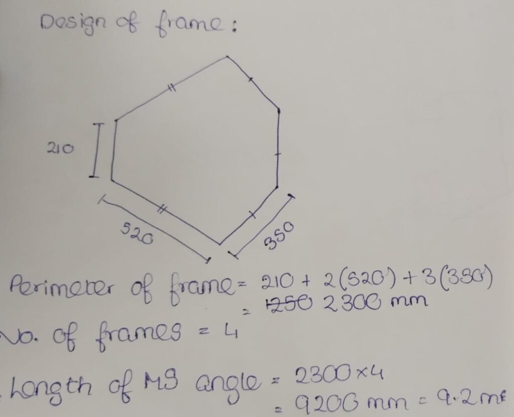
- Mild Steel Angle Bars 20mm wide, 3mm thick
The polypropylene mesh was readily available in the Vigyan Ashram Inventory. I then calculated the quantity of MS angles required and a tentative cost of procurement. The required length came out to be approximately 9.2 meters, as the bars available with the vendor were 18 ft or 5.5 meters long, I decided to purchase two angle bars with a total weight of 10.5 kgs at a rate of Rs 61/kg.
October 15, 2024 – October 16, 2024
Cutting and Grinding Metal Frames
The obtained Steel angle bars were then cut using a tabletop Cutting wheel into the required dimensions. I then proceeded to remove the rust formed on the existing frames by using a grinding wheel. This particular activity took longer then expected as the total number of surfaces to be finished were 100 and each required attention to detail. I further grinded all the cut edges using the grinding wheel.
I also drilled holes at specific positions on the inner surface of the Metal Frame for fixing the Perforated PP sheet with the help of the Vertical Milling Machine.
October 18, 2024 – October 20, 2024
Welding the Metal Frames
The Mild Steel Angles after being cut into the required dimensions were to be joined to form the Metal Frames of the Drying Trays. For this, I used the CO2 MIG Welding Machine to precisely join the angles together. The Welded surface was finished with the help of handheld grinding to achieve a smooth surface.
October 21, 2024
Painting the Metal Frames
To avoid rusting of steel components we often paint them or galvanize the surface to avoid contact with atmospheric moisture. I coated the Mild Steel Drying Tray Frames with a Rust resistant Red Oxide Primer based paint carefully to cover the entire exposed surface of the frame to avoid rusting of the metal. For this I mixed the primer with Paint Thinner in the ratio 2:1 for getting an effective coat of the paint.
October 22, 2024
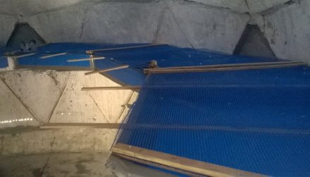
Fixing the PP Mesh onto the Metal Frames
I fixed the PP Mesh onto the Metal frames to finally complete the Fabrication of the Drying Trays. For this, I used Self-driven screws to hold the PP Mesh on the Metal frames. The Trays were then covered with permeable cotton sari cloth for holding the substrate in the trays while allowing the air to pass freely between the trays. Now the trays were ready for Prototype Testing.
December 12, 2024
Design of Experimental Conditions
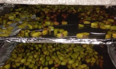
From the previous work done by Vigyan Ashram on various such Forced Convection Dryers we have an understanding of the ideal drying conditions for various substrates. For the previously aimed substrates, i.e. chilies the drying conditions were more or less similar and hence testing conditions for a dryer aimed at current substrate, i.e. moringa leaves could be assumed the same.
From my discussion with the Food Lab staff Ms. Reshma I was able to understand the requirements of the dryer which was mainly to dry a capacity of 20kg/day of leafy vegetables like coriander, moringa leaves and such from a moisture content of 90% to <5%. From literature research I was able to conclude that a temperature range of 48-64 degrees Celsius was sufficient for a achieving satisfactory drying rates while not compromising on product quality.
In our forced convection setup, precise control of airflow is essential to achieve the desired behavior. Inspired by the milking analogy, where milk is squeezed out in stages, we applied a similar approach in our dryer. Hot air is drawn from the collector into the drying chamber using an inlet fan until the temperature reaches a set upper threshold. The air is then held in the chamber for 10 minutes to allow adequate heat absorption and humidification. Subsequently, the inlet fan is turned off, and the outlet fan is activated to expel the humid air.
Testing conditions:
- Substrate: Sawdust
- Moisture content: 50%
- Dry Weight: 9 kg
- Bulk Weight: 18 kg
- No. of Trays: 9 (one for each stack)
- Initial Data Logger Position: Middle of Drying chamber
December 13, 2024
Arrangement of Trays
As per my discussion with Dr. Arun Dixit, to have an unbiased data collection we should randomized the arrangement of the nine trays in either of the four orientations on a rack. this randomization must be done through a random function generator. For this, I made the following cprogram which helps in generating a randomized arrangement of trays.
#include <iostream>
#include <vector>
#include <cstdlib>
#include <ctime>

// Function to check if the sequence meets the constraints
bool isValidSequence(const std::vector<int>& sequence) {
    // Count occurrences of each orientation
    std::vector<int> count(4, 0); // For 4 orientations numbered 1 to 4
    for (int orientation : sequence) {
        count[orientation - 1]++;
        if (count[orientation - 1] > 3) return false; // More than 3 of the same orientation
    }

    // Check if no tray is directly below another with the same orientation
    for (int i = 0; i < 6; i++) {
        if (sequence[i] == sequence[i + 3]) return false;
    }

    return true;
}

int main() {
    std::srand(std::time(0)); // Seed for randomness
    std::vector<int> sequence(9); // To store the sequence

    while (true) {
        // Generate a random sequence
        for (int i = 0; i < 9; i++) {
            sequence[i] = 1 + std::rand() % 4; // Random number in range [1, 4]
        }

        // Check if the generated sequence is valid
        if (isValidSequence(sequence)) break;
    }

    // Print the valid sequence in list format
    std::cout << "Valid tray arrangement sequence (list format):\n";
    for (int i = 0; i < 9; i++) {
        std::cout << "Tray " << i + 1 << ": Orientation " << sequence[i] << "\n";
    }

    return 0;
}
Explanation:
- Constraints Handling:
- Max 3 Trays per Orientation: The
isValidSequencefunction checks if any orientation exceeds 3 occurrences. - No Same Orientation Directly Below: The same function ensures that trays in positions
(i, i+3)don’t have the same orientation.
- Max 3 Trays per Orientation: The
- Random Sequence Generation:
- Trays are assigned random orientations using
1 + std::rand() % 4.
- Trays are assigned random orientations using
- Validation Loop:
- If the generated sequence fails validation, the program regenerates it until a valid sequence is found.