In food processing, the loss on drying (LOD) process is a method used to determine the moisture content of a product by measuring the weight loss upon drying. The choice of insulation material for the drying process is crucial for accurate and efficient moisture analysis. The commonly used materials include:
1. Cellulose Fiber Paper
- Properties: Excellent thermal stability and heat distribution.
- Advantages: Cost-effective, disposable, and provides even heat distribution, minimizing hotspots and ensuring consistent drying.
2. Glass Wool
- Properties: Made of fine fibers of glass, providing good thermal insulation.
- Advantages: Non-combustible, provides good thermal insulation, and maintains consistent drying conditions.
3. Ceramic Fiber Blankets
- Properties: Composed of high-purity ceramic fibers, withstanding very high temperatures.
- Advantages: High temperature resistance, excellent thermal stability, reusable.
4. Silicone Mats
- Properties: Made of flexible silicone material with good thermal stability.
- Advantages: Flexible, durable, reusable, provides even heat distribution, non-stick surface.
5. Foam Glass
- Properties: Lightweight, cellular glass material with good thermal insulation.
- Advantages: Chemically inert, moisture-resistant, provides effective thermal insulation.
Choosing the Right Insulation Material
- Temperature Stability: Select a material that can withstand the drying temperature without degrading.
- Even Heat Distribution: Ensure the material provides uniform heat to avoid hotspots.
- Moisture Resistance: The material should not absorb moisture, affecting the drying process.
- Cost and Reusability: Consider the cost and whether the material needs to be disposable or reusable based on the application.
Usage in Loss on Drying
In practice, the insulation material is used in ovens, desiccators, or drying chambers where food samples are dried. It helps maintain a stable temperature environment and ensures consistent and accurate measurement of moisture content.
For a 275 lumen, 250W BR125 IR clear incandescent bulb used in food processing, the insulation material must withstand the bulb’s heat output while providing effective thermal insulation.
Ceramic Fiber Blankets
- Temperature Resistance: Excellent; typically withstands temperatures up to 1260°C (2300°F).
- Advantages: High thermal stability, effective heat insulation, reusable.
- Usage: Suitable for high-temperature applications, ensuring minimal heat loss and maintaining stable conditions around the bulb.
2. Glass Wool
- Temperature Resistance: Good; can typically handle temperatures up to 500°C (932°F).
- Advantages: Good thermal insulation properties, non-combustible, cost-effective.
- Usage: Commonly used for thermal insulation in various applications. Provides effective insulation but may need to be protected from direct exposure to very high heat to prevent degradation over time.
3. Foam Glass
- Temperature Resistance: Good; can handle temperatures up to 430°C (806°F).
- Advantages: Chemically inert, excellent moisture resistance, provides effective thermal insulation.
- Usage: Suitable for applications where chemical resistance and moisture resistance are important, along with good thermal insulation.
4. Cellulose Fiber Paper
- Temperature Resistance: Moderate; up to about 200°C (392°F).
- Advantages: Cost-effective, even heat distribution, disposable.
- Usage: More suited for lower-temperature applications but may not be ideal for the high heat of a 250W bulb.
Parameters for Calculation
Thermal Conductivity (k):
For ceramic fiber, typically k=0.03 W/m\k
External Convective Heat Transfer Coefficient (h):Typically for air, h= 10−25 W/m2\k
Chamber Dimensions: 27 cm×20 cm×27 cm
Formula for Critical Thickness:

Given the chamber’s application and heat considerations, typical insulation thicknesses for high-temperature applications (such as ceramic fiber) range between 1 to 5 cm.
Let’s assume a practical effective thickness of 2.5 cm (0.025 m) for ceramic fiber insulation.
Calculation for Heat Transfer Reduction
To verify this choice, let’s calculate the heat loss reduction using Fourier’s Law for heat conduction.


Effective Heat Loss Calculation:
To incorporate the 5% heat loss due to ventilation:


To account for this total heat loss, we should slightly increase the insulation thickness to ensure adequate thermal management. Using the adjusted total heat loss, the effective insulation thickness can be recalculated:
Rearrange Fourier’s Law to solve for thickness d:

Impact of Powder Coating on Heat Transfer:
Thermal Resistance of Powder Coating
Powder coatings generally have low thermal conductivity, which adds a small thermal resistance. For simplicity, let’s assume a typical thermal conductivity k coating for powder coatings is about 0.2

Combined Thermal Resistance:


Effective Heat Transfer Calculation:


Another material:


So the effective thickness should be approximately 2.38 cm.
Let’s compare the insulation materials (ceramic fiber, phenolic foam, and cellulose fiber paper) based on several key factors relevant to your closed chamber (27 cm × 20 cm × 27 cm) with a 250W incandescent bulb and powder-coated mild steel (MS) exterior. We’ll consider:
- Thermal Conductivity
- Temperature Resistance
- Thickness for Effective Insulation
- Cost and Practicality
- Moisture Resistance
- Durability and Longevity

Best Overall Choice: Phenolic Foam
Practical Thickness: A thickness of 2.5 cm provides adequate insulation while being practical to apply.
Calculations:
Closed chamber of LOD device (MS with powder coating) wall thickness :


Determine the Thickness of the Mild Steel (MS) Wall with Powder Coating:

The required wall thickness for Mild Steel (MS) with powder coating to maintain the desired temperature with 5% ventilation losses is approximately 15.24 mm.
Let’s calculate the required insulation thickness for each of the listed materials to maintain the inside temperature of 110°C with an outside ambient temperature of 30°C, accounting for 5% ventilation losses


Project Electronics:
Components:
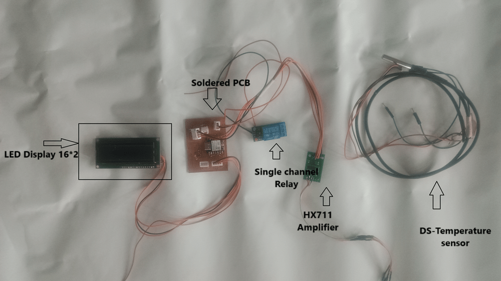
Load Cell– A load cell converts a force into an electrical signal that can be measured. The electrical signal changes proportionally to the force applied. There are different types of load cells: strain gauges, pneumatic, and hydraulic. In this tutorial, we’ll cover strain gauge load cells.


The wires coming from the load cell usually have the following colors:

HX711 Amplifier– The HX711 amplifier is a breakout board that allows you to easily read load cells to measure weight. You wire the load cell wires on one side, and the microcontroller on the other side. The HX711 communicates with the microcontroller using two-wire interface (Clock and Data).

Circuit Diagram:

Components: The objective of this project is to automate and optimize the drying process, but I am currently running manual tests to refine the procedure. Once the optimal parameters are established, the system will be automated using a Xiao ESP32C3 microcontroller to manage real-time sensor inputs, cloud-based data monitoring, and automated control features.
- Xiao ESP32C3 microcontroller: Will manage sensor data, relay control, and cloud communication.
- Load cell: Will monitor weight changes to track moisture loss.
- LCD display: For real-time data on weight and temperature.
- DS series temperature sensor: Will ensure the chamber’s internal temperature is controlled.
- Relay: Will control the heating element, turning it off when the temperature exceeds 105°C.
- Exhaust fan: Introduced to resolve moisture buildup inside the chamber.
- Firebase integration: For future remote monitoring of real-time data via a web interface.
In my latest project, I’ve been conducting manual experiments to develop an optimized drying system for peanut drying, with plans to later automate the process using IoT technology.
Manual Peanut Drying Test Results:
Currently, I am manually conducting the tests. Each test was run over an 11-minute period, starting with 50 grams of peanuts in the first test. From the second test onward, the peanuts began to get roasted. The initial weight for each test was set as the final weight of the previous test. Temperature was manually measured with a thermometer, and weights were recorded using a food lab balance. Here are the updated test results:


These results show varying degrees of moisture loss, but from the second test onward, the peanuts began to roast, indicating excessive heat exposure. I am fine-tuning the manual procedure to improve the balance between drying and roasting.
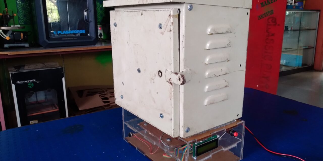
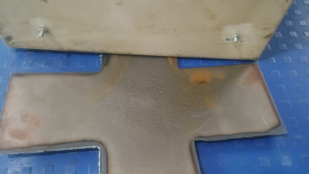
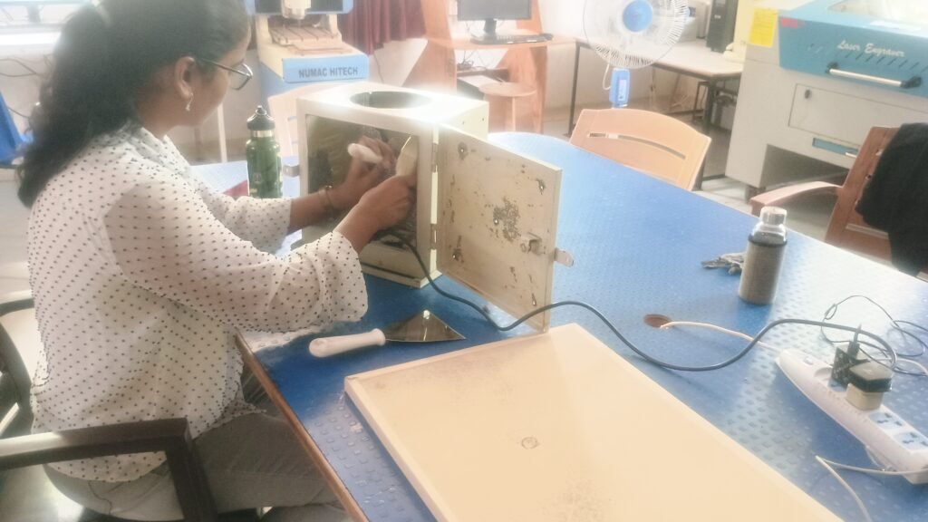
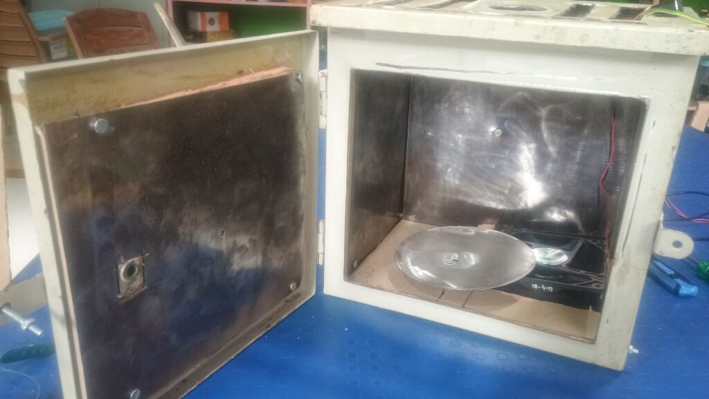
Modifications in the Heating Chamber:
One major issue I encountered was moisture condensation at the bottom of the heating chamber, which negatively affected the drying process. To address this, I welded the bottom of the chamber to prevent moisture from pooling. While this reduced the condensation at the bottom, it caused moisture to move toward the chamber’s walls. Unfortunately, this led to another issue—rust formation on the walls at around 10 cm from the bottom. This observation highlights the need for further modifications to optimize moisture handling and improve the chamber’s durability.
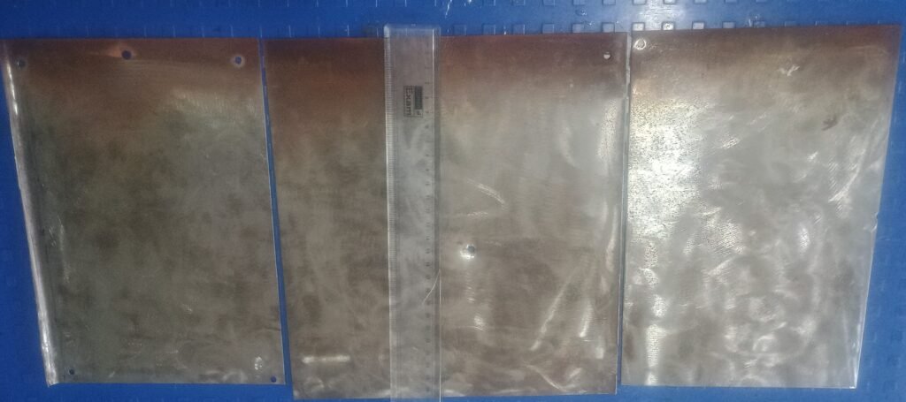
Assembling New Phenolic Foam Insulation:
To enhance the drying chamber’s efficiency, I installed a phenolic foam sheet as an insulator. This insulation significantly improved heat retention, but it also caused moisture to get trapped inside the chamber, leading to suboptimal drying conditions.
To address the moisture buildup, Mr. Prasad Patil suggested turning on the exhaust fan momentarily to allow the trapped moisture to escape. I manually implemented this solution, turning the fan on after a 5-minute delay during the test, and I’ll continue monitoring the impact of this on moisture and heat retention.
Challenges and Manual Solutions:
- Moisture Trapping:
The improved insulation trapped moisture, which was addressed by manually turning on the exhaust fan after a 5-minute delay to help release the moisture without significant heat loss. - Temperature Control:
I manually monitored the chamber’s temperature using a thermometer, ensuring it didn’t exceed 105°C. Temperature control will be automated in the future to maintain consistent drying conditions. - Weight Monitoring:
I manually weighed the peanuts using a food lab balance after each test to track the loss in moisture. This will also be automated using a load cell in future iterations of the system

