
The Fourth workshop for college was held from 04th Nov 2022 to 06th Nov 2022 in which 16 students of Jawaharlal Institute of Technology, Borawan participated.
These students were from different departments. In this batch there were 04 students of Electrical branch, 12 students of Electronic branch.
We made three groups of students.
It was a three day workshop. In this, on the first day, information about the machines were given to the students and all the software related to it were taught to the students.
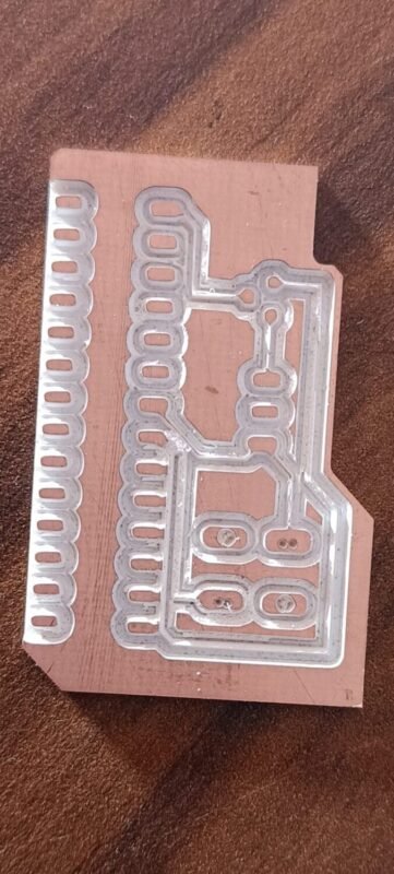
In this workshop they also learned to design PCB and make a simple PCB. A PCB milling system is a single machine that can perform all of the required actions to create a prototype board, with the exception of inserting vias and through hole plating. Most of these machines require only a standard AC mains outlet and a shop-type vacuum cleaner for operation. To design this PCB


A group of them made a project using the sound playback model and then connected the LEDs to the speakers.
Sound playback module
It is a multiple‐message record/playback device. It supports true voice recording, non‐volatile storage, and playback capability for 10 seconds. This module is simple to use. You can have direct control by push button on the module itself or you can control automatically by microcontroller such as Arduino.

In this module there are three buttons named REC, PLAYE and PLAYL
whenever we want to record our voice by pressing REC button.
There are two modes to play the voice in the voice chip:
1. Playback, Edge-activated: If the module detects the HIGH signal on the pin, then the device starts the playback cycle. Playback cycle continues until an End-of-Message (EOM) marker is encountered or the end of the memory space is reached. After completion of the playback cycle, the device automatically powers down itself and into the standby mode.
2. Playback, Level-activated: If the module detects the LOW to HIGH signal on this pin, then a playback cycle is initiated. Playback continues until PLAYL is pulled LOW or an End-of-Message (EOM) marker is detected, or the end of the memory space is reached. The device automatically powers down to standby mode upon completion of the playback cycle.


2nd Project
Second group updated the old project. Old Project did not turn the motor on or off automatically. So we changed its programming and then added relay to it.
Component Used
- Arduino Uno
- Ultrasonic sensor
- relay
- LEDs
About component
What is Arduino ?
Arduino is an open-source electronics platform based on easy-to-use hardware and software. Arduino boards are able to read inputs – light on a sensor, a finger on a button, or a Twitter message – and turn it into an output – activating a motor, turning on an LED, publishing something online. You can tell your board what to do by sending a set of instructions to the microcontroller on the board. To do so you use the Arduino programming language (based on Wiring), and the Arduino Software (IDE), based on Processing.
Over the years Arduino has been the brain of thousands of projects, from everyday objects to complex scientific instruments. A worldwide community of makers – students, hobbyists, artists, programmers, and professionals – has gathered around this open-source platform, their contributions have added up to an incredible amount of accessible knowledge that can be of great help to novices and experts alike.
Arduino was born at the Ivrea Interaction Design Institute as an easy tool for fast prototyping, aimed at students without a background in electronics and programming. As soon as it reached a wider community, the Arduino board started changing to adapt to new needs and challenges, differentiating its offer from simple 8-bit boards to products for IoT applications, wearable, 3D printing, and embedded environments.

About Ultrasonic
An ultrasonic sensor is an electronic device that measures the distance of a target object by emitting ultrasonic sound waves and converts the reflected sound into an electrical signal. Ultrasonic waves travel faster than the speed of audible sound (i.e. the sound that humans can hear).

Ultrasonic sensors have two main components: the transmitter (which emits the sound using piezoelectric crystals) and the receiver (which encounters the sound after it has traveled to and from the target).
To calculate the distance between the sensor and the object, the sensor measures the time it takes between the emission of the sound by the transmitter to its contact with the receiver. The formula for this calculation is D = ½ T x C (where D is the distance, T is the time, and C is the speed of sound ~ 343 meters/second).
Relay
A Relay is a simple electromechanical switch. While we use normal switches to close or open a circuit manually, a Relay is also a switch that connects or disconnects two circuits. But instead of a manual operation, a relay uses an electrical signal to control an electromagnet, which in turn connects or disconnects another circuit.
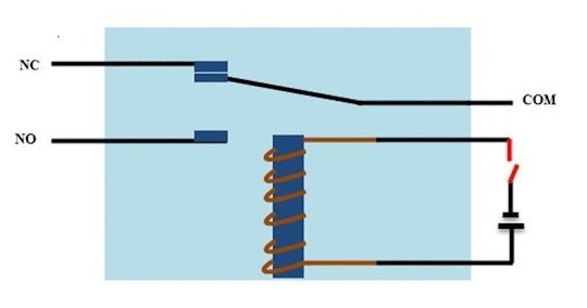
Relays can be of different types like electromechanical, solid state. Electromechanical relays are frequently used. Let us see the internal parts of this relay before knowing about it working. Although many different types of relay were present, their working is same.
Code :
#define trigpin 7

#define echopin 6

int led1 = A0;
int led2 = A1;
int led3 = A2;
int led4 = A3;
int led5 = A4;
void setup()
{
Serial.begin(9600);
pinMode(trigpin, OUTPUT);
pinMode(echopin, INPUT);
pinMode(11,OUTPUT);
pinMode(led1, OUTPUT);
pinMode(led2, OUTPUT);
pinMode(led3, OUTPUT);
pinMode(led4, OUTPUT);
pinMode(led5, OUTPUT);

digitalWrite(led1, LOW);
digitalWrite(led2, LOW);
digitalWrite(led3, LOW);
digitalWrite(led4, LOW);
digitalWrite(led5, LOW);
digitalWrite(11, HIGH);

delay(1000);
}

void loop()
{
int duration, distance;
digitalWrite(trigpin, HIGH);

delayMicroseconds(1000);
digitalWrite(trigpin, LOW);

duration = pulseIn(echopin,HIGH);

distance = ( duration / 2) / 29.1;
Serial.println("cm :");
Serial.println(distance);

if( (distance > 3) && (distance <= 7) )
{
digitalWrite(led1, HIGH);
digitalWrite(led2, HIGH);
digitalWrite(led3, HIGH);
digitalWrite(led4, HIGH);
digitalWrite(led5, HIGH);
digitalWrite(11,HIGH);
}
else if( (distance > 7) && (distance <= 10) )
{

digitalWrite(led1, LOW);
digitalWrite(led2, HIGH);
digitalWrite(led3, HIGH);
digitalWrite(led4, HIGH);
digitalWrite(led5, HIGH);

} else

if( (distance > 10) && (distance <= 17) )
{

digitalWrite(led1, LOW);
digitalWrite(led2, LOW);
digitalWrite(led3, HIGH);
digitalWrite(led4, HIGH);
digitalWrite(led5, HIGH);
} else

if( (distance > 17) && (distance <= 25) )
{

digitalWrite(led1, LOW);
digitalWrite(led2, LOW);
digitalWrite(led3, LOW);
digitalWrite(led4, HIGH);
digitalWrite(led5, HIGH);
} else

if( (distance > 25) && (distance <= 27) )
{

digitalWrite(led1, LOW);
digitalWrite(led2, LOW);
digitalWrite(led3, LOW);
digitalWrite(led4, LOW);
digitalWrite(led5, HIGH);
}

if( distance ==27 )
{
digitalWrite(led1, LOW);
digitalWrite(led2, LOW);
digitalWrite(led3, LOW);
digitalWrite(led4, LOW);
digitalWrite(led5, LOW);
digitalWrite(11, LOW);
}

}
The third group thought transmitting wireless sound.
So they used 433 MHz RFID Module and with the help of that they transmitted voice.
Component Used
- 433 MHz RFID module
- 3.5 mm plug pin
- speaker
- supply battery
Component Information
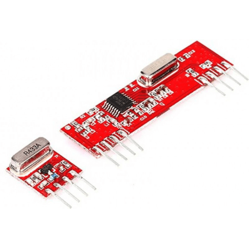
433 MHz RFID module
This hybrid RF Transceiver Module provides a complete RF transmitter and receiver module solution which can be used to transmit data at up to 3KHz from any standard CMOS/TTL source.
The transmitter module is very simple to operate and offers low current consumption (typical. 11mA). Data can be supplied directly from a microprocessor or encoding device, thus keeping the component count down and ensuring a low hardware cost.
The RX – ASK is an ASK Hybrid receiver module. The RF Transmitter Receiver Module is an effective low-cost solution for using 433 MHz. The TX-ASK is an ASK hybrid transmitter module. TX-ASK is designed by the saw resonator, with an effective low cost, small size and simple to use for designing.
Specifications of 433MHz RF Transmitter Receiver Wireless Module:-
- Range in open space(Standard Conditions) : 100 Meters
- RX Receiver Frequency : 433 MHz
- RX Typical Sensitivity : 105 Dbm
- RX Supply Current : 3.5 mA
- RX IF Frequency : 1MHz
- RX Operating Voltage : 5V
- TX Frequency Range : 433.92 MHz
- TX Supply Voltage : 3V ~ 6V
- TX Out Put Power : 4 ~ 12 Dbm
Circuit Diagram

we made a 6.5k and 3.3k resistor by 1k resistor to joint them in series and parallel. for antenna we used 2.5 mm aluminum wire and roll it.


