Laser Machine
About laser
Laser stand for Light amplification by stimulated emission of radiation.when atoms of active system of laser medium absorbed energy goes to the excited energy state , after completation of life time it jumped from higher energy level to the ground energy level.during this transition it emit photons by the process of stimulation emission.these photons get applied in resonator,emits Laser light which is highly coherent, monochromatic, intense and unidirection.
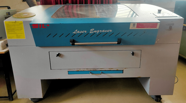
- FEATURES
- Top cutting precision and positional accuracy
- Improved edge quality and surface finish
- Strong repeatability
- The use of materials not cut by traditional devices
- Drilling and engraving in addition to cutting
- Negligible workpiece degradation
- Cost-effectiveness
Laser Cut Smart Phone Stand
INTRO: LASER CUT SMART PHONE STAND
STEP 1: measure your phone
First, we need to get some measurements. Here with the detail we only need the height, width and thickness of the phone.
Calipers are very helpful for this kind of measurement. With small objects like this, it’s much easier to work in metric, so I measure my phone in millimeters.
STEP 2: Create Sketch
Step 3: Enter the Dimensions
Now that you have a rectangle, click on the Stop Sketch button. You can drag Shift+Middle Mouse to move the scene around and see the sketch you just made.
Now it’s time to create a solid object to represent the phone- go to Create > Extrude and click on Rectangle Sketch
STEP 4: Extrude rectangle
STEP 5: Fillet corners
Step 6: Status Phone Model
To model a phone stand, you’ll need to figure out which position you want the phone to be in while it’s on the stand. You can do this by rotating and rotating the phone. You can rotate it as you like.
Step 7: Make the Laser Cut Profile
Now that our design is finished, we need to export the profile lines so that we can laser cut them. To do this, go to Sketch > Create Sketch, then click Panel. Rename the sketch in the browser so you can keep track of everything.
Step 8 :-Create a new sketch from the side face of the panel
Step 9 :-Right-click the sketch in the browser, then choose Save as DXF, then save the files to a folder you can easily find later.
Save as DXF for Illustrator Import
Step 10: Laser Cutter Settings
The document size for this project is already 24″X36″, so the size should be set to match. Illustrator Print Dialog This project uses 1/4″ (6mm) plywood, so the speed is half (10%) as fast as the 1/8″ plywood settings from the last two lessons, and for good measure the power is set to 95% is extended to.
Step 11: Finished Products
First cleaning it and , the stand fits the phone properly. This project may work better with a thinner material.
Assignment 1-Laser Cut Cart-Pushing Robot

Materials
- 3mm plywood*
- TT 6V Geared Motor
- 2 AA Battery Holder with Switch and Wire Leads
- 2 AA Batteries
For the Laser Cut Cart-Pushing Robot design consider the following steps
Download the SVJ file.
I have downloaded this file from internet we can make design using Vector Illustration Software or CorelDraw.

Step1:- Use RD works Software
Download and open the RD work software.
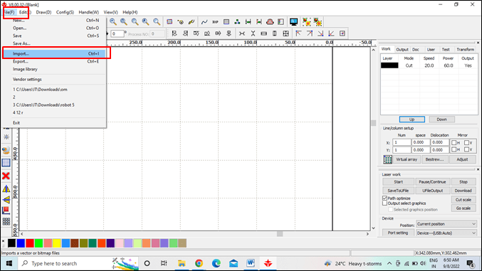
Go to the file menu and select import and emport
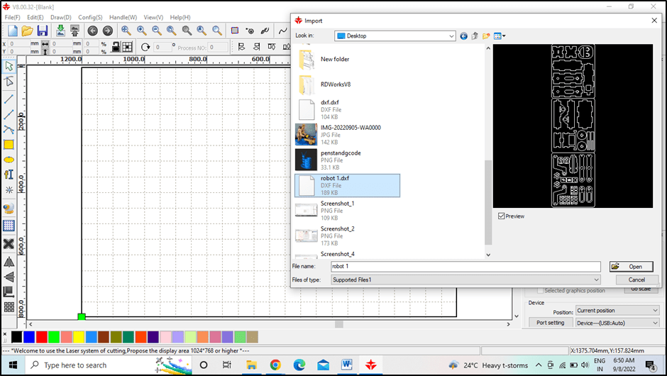
Step 2 :-Select the Dxf file you want to open in RD works.
Step3:-Set the Speed & power
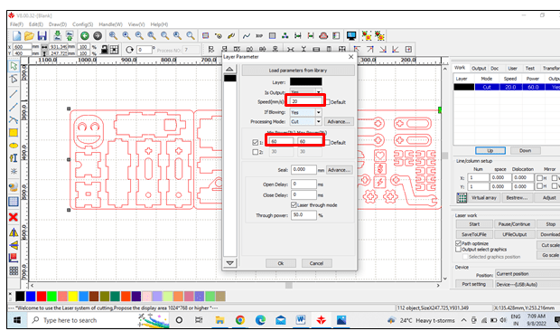
Select design you have to cut ,give it proper color default color is black .
Doulble click on cut mode present at right side of the screen with color layer.
Note- that the speed and power for plywood (3 mm)is set as 20mm/s and60% respect.as per group assignment
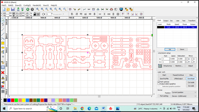
Step4:- Make sure that USB port is properly connected with laser cutter other wise it will provide communication error.
Click on download and file will be downloaded in machine
Step 5:-Hands on Laser cutter
This is the monitoring panel of SIL laser cutter. Through that we can change different parameters of machine before cutting the materials.
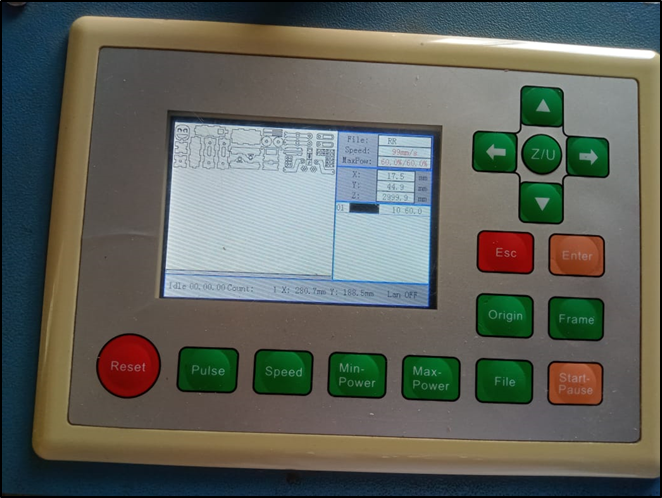
Step 6:– Placed the material on the bed.
Set the origin
Adjust Z axis i.e position of laser head from the material surface.
Select the file in panel. identify the cutting area with frame.
Click on start/ pause button.

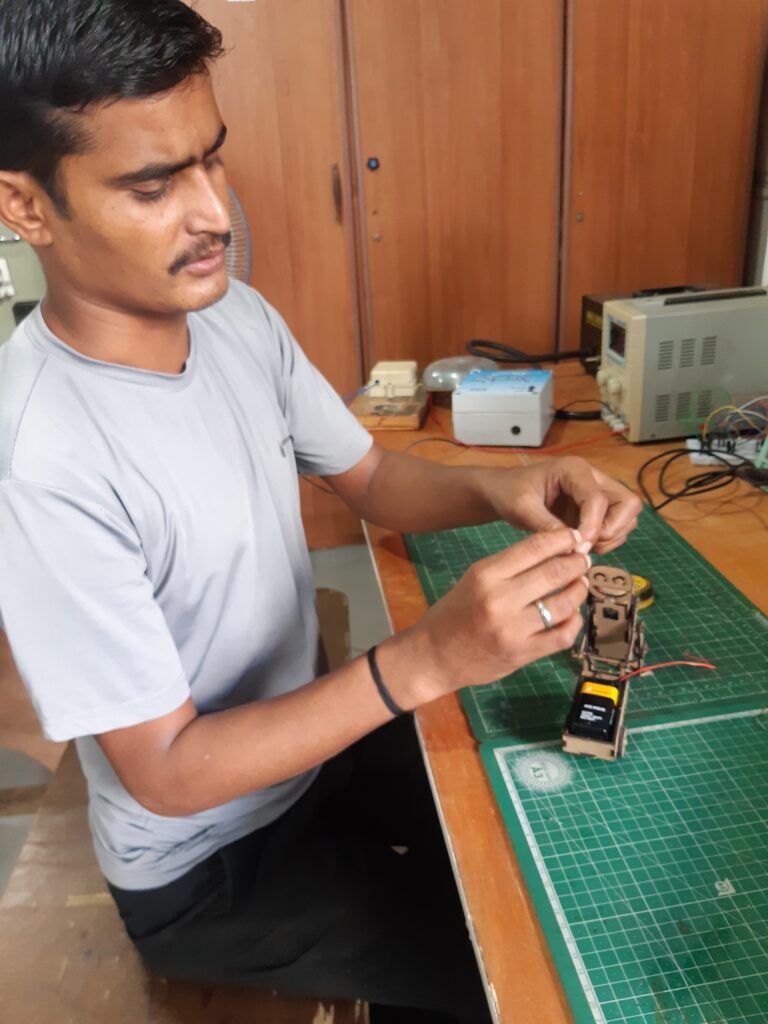
Assembling all parts of the robot

Connecting all electrical components
3D printer
The term “3D printing” originally referred to a process that deposited a binder material layer by layer on a powder bed with inkjet printer heads.
printing
Before printing a 3D model from an STL file, it must first be checked for errors. Most CAD applications produce errors in the output STL files
of the following types:
hole
faces the normal
self intersections
noise balls
manifold errors
overhang issues
A step in STL generation known as a “repair” corrects such problems in the original model.
Once complete, the STL file needs to be processed by a piece of software called a “slicer”, which converts the model into a series of thin layers and produces a G-code file containing a specific type 3D Printer (FDM) compliant instructions. printer). This G-code file can then be printed with 3D printing client software (which loads the G-code, and uses it to instruct the 3D printer during the 3D printing process).

Printer resolution describes the layer thickness and X-Y resolution in dots per inch (dpi) or micrometers (μm). Typical layer thicknesses are about 100 µm (250 dpi),

finishing
Although printer-generated resolution is sufficient for many applications, greater accuracy can be achieved by printing a slightly larger sized version of the desired object in standard resolution and then removing the material using a high-resolution subtractive process.
3D CAD Design
Fusion software, it was explained in detail in the class, it is designed in Autodesk Fusion 2D 3D, it runs with education ID.
Whenever a design is made in it
so he always has to title
In this, at least the command has to be given which can correct the design.
then we made a design
In which a circle is taken of 30 mm
After setting its size and then extruding it and
flat file on top of that and
By giving command in place printer, STL file is saved in it and tax code is generated.

Thunder laser software has been given information about it and it was also told to make some designs in which we also made the design
told the cutting command
Cardboard runs at max power 30 speed 50
And engraving has 15 power speed 280

Information about electronic components was given in the class today.
Resistor – in which information about resistors is given, it is of many types and it is told about its color code that it is told about extracting its value V=IR
Capacitor – works in units of Faraday and
serves to filter the voltage
tells its value in micro
it is of two types
Ceramic Paper, Electro Lightning
Diode – It allows current to flow in one direction and blocks the reverse current
Transistor– it has 3 plugs ammeter base collector
Motor servo motor stepper motor
Servo motors work in angle grinders
Stepper motor works in number of angles
Relay – It acts as an electric switch in which a magnetic leaf is attached.
display -It is a 16 character basic character by 2 line alphanumeric display. White text on a blue background. The interface code is freely available. Works with almost any microcontroller
sensor – A sensor is a device that generates an output signal for the purpose of sensing a physical phenomenon. Different types of light sensor. Different types of light sensor. image sensor pressure sensor tactile sensor light sensor pressure sensor
microcontroller – A microcontroller (MCU for microcontroller unit) is a small computer on a VLSI integrated circuit (IC) chip. Contains in a Microcontroller A microcontroller (MCU for microcontroller unit) is a small computer on a VLSI integrated circuit (IC) chip. in a microcontroller
Arduino – Arduino is an open-source hardware and software company, project, and user community that designs and manufactures single-board microcontrollers and microcontroller kits for building digital devices.
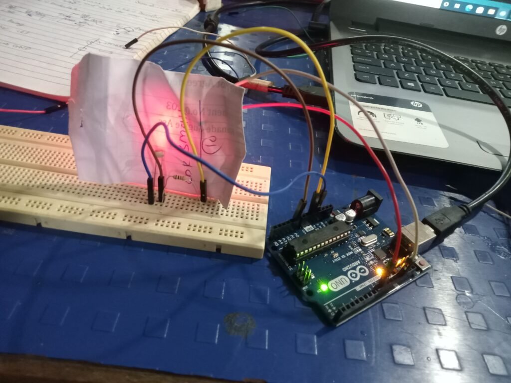
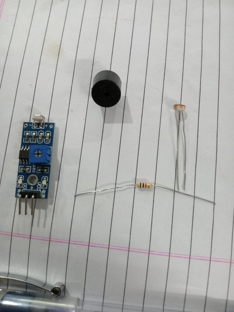
ESP32 – A range of low-cost, low-power system on chip microcontrollers with integrated Wi-Fi and dual-mode Bluetooth. After that programming with Arduino + buzzer + ldr sensor.
Arduino+buzzer+ldr sensor programming

Arduino+buzzer+led+ldr sensor programming

Eagle software
EAGLE – EAGLE is a scriptable electronic design automation application with schematic capture, printed circuit board layout, auto-router and computer-aided manufacturing features. EAGLE stands for Easy to Implement Graphical Layout Editor
General pcb
Control panel
Ic
about pcb
never cross wiring in pcb
Cutting is done by saving the PCB file in Image and Gyber scale
In this, changing the wire to make it thicker / smaller, sets it in the width.
After this the xyz bed is set for the pcb milling machine
then later a pcb was designed

Assignment 2
Arduino+RelayProgramming
Informations about relay was given in class today.
First of all, we have installed a uv tube in water filter chamber in dream house. And I grouped Arduino +relay to make water pump on/off at regular time.
First made drawing of Arduino +relay programming

After, wiring Arduino +relay wiring and plug socket.
Coding was done in Arduino

Later a box was made for it with a laser cutter
Arduino +relay and plug socket are installed in it
And uv tube and water pump were connected by installing in dream house

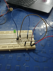
LDR +darkness sensor
The circuit of a sensor is given by Suvarna Mam in which ldr darkness sensor is used and as soon as it gets dark on the sensor the LED light turns on
9volt = battery
LDR =1
Transistor =BC547
Resistance =50k or 1k
Basic parameter checking of solar micro dome
An assignment has been given in which two solar panels are installed one of 3 watt panels are installed in parallel connection and on grid
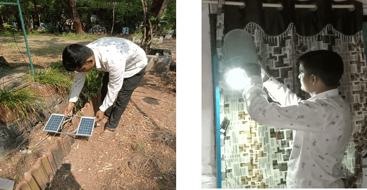
So by wiring them, the lamp was run inside the room and its light was seen and then mam was also checked.
The voltage and ampere of the lamp were checked, and the same was seen there and the voltage and Amp were checked as much as the wire was found to be correct.
| Voc | 10.5 |
| Isc | 410mA |
| Pmp | 03wp |
| Vmp | 8.2v |
| Imp | 375mA |
Assignment 3 weight machine repair of food lab
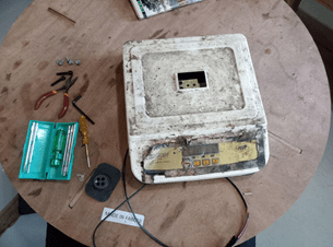
got the assignment to repair weight machine in fablab
First of all, I opened the machine and checked from inside. Some wires were loose. I corrected it.

One wire was broken, so it was soldered a new one.
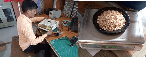
I checked my work, and the machine turned on
He was later charged
Assignment 4 Kitchen exit fan
Problem
There is a lot of smoke in the kitchen where the food is cooked, so there was a discussion with Dixit sir and Swarna to take it out by turbine or by exhaust fan, in which Kulkarni sir suggested to install on grid system exhaust fan by solar.
purpose
Our main aim is to solve the problem of smoke in our kitchen due to burning of wood in wood stove. Our main objective is to reduce the smoke using various methods
There is smoke in the kitchen, to get it out, an exit fan has to be set up.
First of all I took 12 volt solar panel and checked its voltage and amp and
Checked by running each 12v/0.155 exit fan on it.
After checking the solar panel and fan were soldered.
After this, the place where the stove burns in the kitchen, chose that place where there is more smoke.
Then the exhaust fan was installed.
Then Suvarna ma’am checked and it is working perfectly to blow out the smoke from the kitchen and told to use big exit fan setup
Assignment 5 solar street lights
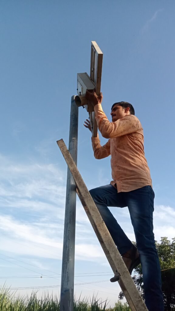
3 solar street lights were checked at Mukhabadir school near Vigyan Ashram
I opened it in the lab in Vigyan Ashram and saw that the LED (smd) panel was defective, then I removed it and soldered a new smd (smd) panel.
It was charged and installed in the school.
Inventory name plate design & cutting
For those who use the tray to keep the material in Fab lab. I created name plates. I had to make a zip by cutting it on an acrylic with a laser cutter, which can be used to put name cards in it.
First of all, the design of the track card was made in Corel Draw, after that it was saved in DXF.
After correcting in RDWORKS, I created a laser cutter file. It was cut on acrylic. Before that, it was cut on cardboard and it was seen that it was correct. I attached it with favi quick. Now it is ready for use.
Conclusion
I learned how to use laser cutter, 3D printer and their software. I improved my designing skills.

