123 D soft ware
introduction to 123d software
3D modeling is a method by which 3-dimensional graphics of any person, object or place are created. The product we get during this is called 3D Model and its creator is called 3D Modeler or 3D Artist (3D Modeler/3D Artist).
There are different software for 3D modeling, we have used 123D software for this 3D modeling.

Use 123 D software
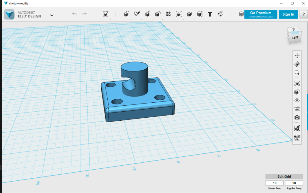
Final design
Use this option
- primitive & sketch :- To take any type of shape
- Construct :- Extrude – To convert from 2D to 3D
- modify: shell – to empty any shape from inside
- Pattern :- Circular pattern – To make any design on the shape
- combine :- Subtract – to hall in shape
- Transform :- Move /rotate & smart scale – To move the shape
Take Box from Primitive Option
And set size

Step 2:- Take a cylinder by going to the Primitive option
And set size

Step3:– Copy the cylinder shape and set the four corners of the object

Step4:– Go to combine and select subtract option
And this option is used to remove the smaller object from the larger object.

Step5:– Take a cylinder by going to the Primitive option again
And set size

Step6:– set to object

Create final design
Wire Getty

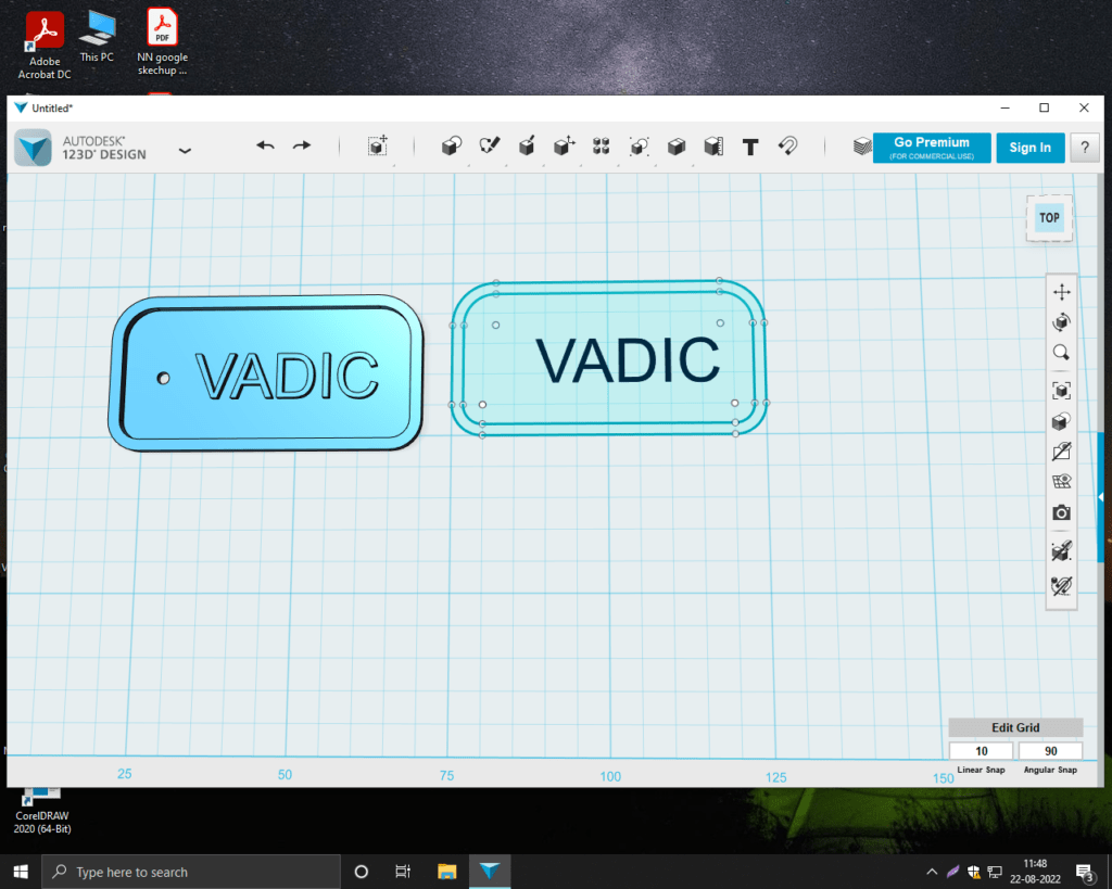
Second Design in 123d design key chain
SolidWorks
What type of software is SolidWorks?
SolidWorks is a 3D CAD software program for machine design released by Dassault Systèmes. SolidWorks is one of the most popular and widely used 3D CAD software programs, used for design in a wide range of industries including industrial equipment, medical equipment, architecture and factory design.
Features of SolidWorks
SolidWorks has a wide range of features such as sheet metal, welding, molding, data conversion, and animation, along with lots of additional options developed by other vendors. This makes it very versatile and suitable for use in many different industries.
ways to use solidworks
SolidWorks is 3D CAD software widely used in design.
How to use SolidWorks to create a 3D part model of a simple flange. We’re going to make the flange shown below.
Create a sketch, a 3D model or a 2D drawing
create a new file
Well then, let’s get started!
Click [File] then [New]. Select [Part] from the file types to create the file, and click [OK].
using the sketch command
After creating the file, create a sketch to create the profile.
When creating a sketch, you must specify the surface you are working on.
I want to create a sketch on the right plane, so choose [right plane ] from the tree on the left side of the screen.
Plastic net cup
First step go to Top plane
Active center line click this point to this point
Active center line click this point to this point and this
Point active three point r click this point make a sames recall
Create this r and this line make the engine
active smart dimension create this line and point make this 10 to 150mm
Make this circle reduce is 5mm
Active sketch filet
This line and this line my angle 95 degree
Go to surface refer surface
I don’t to show this edge delete this feature
Go to edit sketch
Active fit spline
Activate the four surface again click this axis line
See this x looks smooth
Active ticking click this face
Make parameter ticking is 1.5mm
Now the first part be a solid part go to right plane
Active circle click this point center line
This point to active smart dimension make the centerline length is 230mm
And this circle diameter is 20mm linear sketch pattern
Use directional y axis click this circle
And make 9 circle
Activex root cut
Cut this bucket and circular button
Click this cut extrude crease this edge for direction
Bucket is ready
Second Design
designed file
Google Sketchup
SketchUp (formerly Google SketchUp) is 3D modeling software that is easy to use and has an extensive database of user-created models for download. You can use it to sketch (or import) models with all kinds of projects—furniture manufacturing, video game creation, 3D printing, interior design,
Create a home design in Google Sketchup
The opening the window of google SketchUp is show in the image
Step 1:- Select and draw rectangle

Step 2:-Select the push / pull option and drag the wall up

Step 3:– Select the Paint Bucket option and color the wall

Step 4:-Draw a line from one point to another with the Line tool for the roof

Final design home

Second Design in Google Sketchup
CorelDraw Training
CorelDraw is a 2D Design Software
We will open CorelDraw from Google Chrome and to take some design in it, we will take the image from Google and filter it and refresh it and Trace Bitmap it and do Line Art in it in Outline.
Correct the design shape and use the toolbar to group after the shape and zoom in freehand.
To remove any object in laser cutter, it will be saved in DFX file.
Software has to be used for 3d printer.
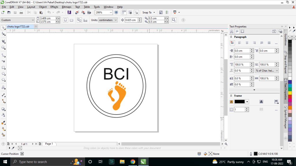
Logo Design in CorelDraw

- First of all select the ellipse tool and refresh it with ctrl + shift and make a circle, its size is to be 700 * 700 MM
- again select the ellipse tool and make a circle inside it and its size is to be 250 * 250
- Then take the pick tool and select both and increase the out line a little (3px).
- After that, we will select the center circle and we will correct it by moving it out of left & right.
- have to select these three by going to the view
- Guidelines
- Alignment Guideline
- Dynamic Guides
- After this you have to select the circle and hold shift and select the background circle and fresh the (c) key and it will come in the center.
- After this, pick up from here and copy it by taking it down
- Now we will select it and with Shift we will also select the second copy.
- Rotate it and copy it
- We will select the center circle and it was 250 * 250 in its measurement, we will do 251 * 251 and 699 * 699 of the circle on the outside.
- will select it and group with ctrl + g If you want to ungroup then you have to use ctrl + u.
- To delete some line using Virtual Segment Delete tool.
- will shape it and (F4) will refresh, after that select it and with its smart
- After this, after selecting from the smart tool, click on the circle
- After this everyone’s shape has to be created and
- After this will take out the back ground sphere
- And those who work on this circle and select it will remove its outline
- and F11 will refresh it and feel the color in it
- After feeling the color, take out the single layer in it
- Now all objects will be separated
- Now after selecting its out line, we will remove its out area and
- Put this background circle on the foot
- This is how our logo is ready
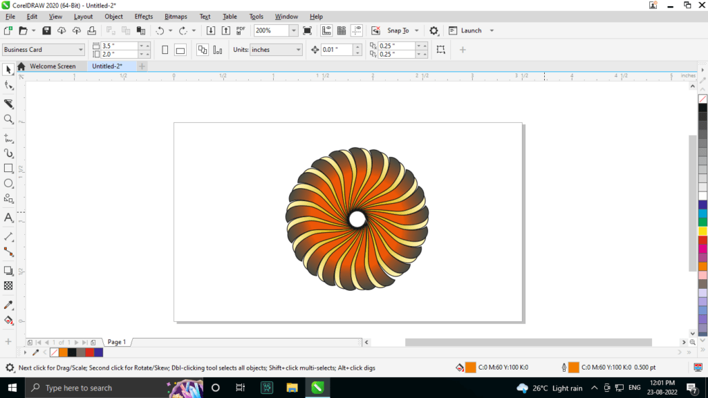
Second Design in CorelDraw
logo & flower
CAD Design Fusion 360
Fusion 360
Fusion 360 is a cloud-based 3D modeling, CAD, CAM, CAE, and PCB software platform for product design and manufacturing. Fusion 360 is a cloud-based CAD/CAM tool for collaborative product development.
Fusion 360 combines organic shape modeling, mechanical design, and manufacturing in one comprehensive package. Autodesk Fusion 360 provides a basic understanding of product design.
Learning Objectives
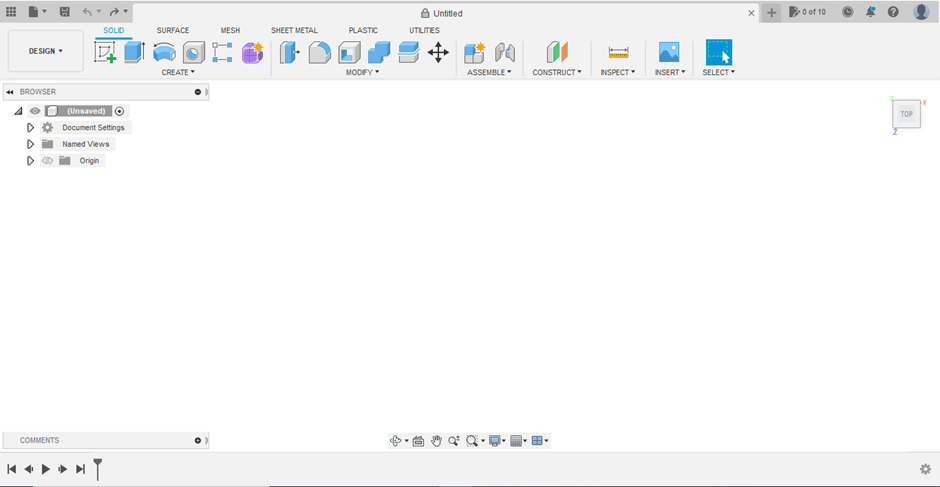
Navigate through the user interface of Autodesk Fusion 360
Understand the design process in Autodesk Fusion 360
Create conceptual designs and organic forms using T-Splines
Design mechanical parts using solid modeling tools
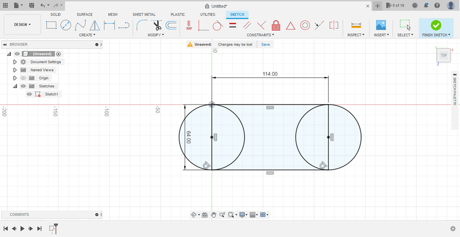
Create Sketch
Enters Sketch mode, where you create geometric profiles that define the foundation of a design. Then use commands like Extrude, Revolve, and Loft to create 3D bodies from sketches.
Select a construction plane, then create lines, arcs, or points to create sketch and construction geometry. Constrain sketches with dimensions and constraints. Select Finish Sketch to exit Sketch mode.
2-Point Rectangle (r)
Creates a rectangle using two points for the diagonal
corners.
Select the first point as the start of the rectangle. Select the second point or specify the width and height values.
Extrude (e)
Adds depth to open or closed sketch profiles or faces. Select an extrusion type, select sketch profiles or faces to extrude, then specify the distance and taper angle. For the Thin Extrude type, specify the wall thickness.

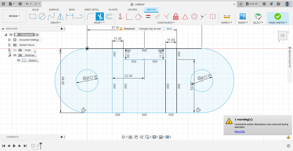
Trim (t)
Trims a sketch curve to the nearest i curve or boundary geometry.
Origin
Sketches
Sketch1
Pause the cursor over the curve to p portion to be trimmed. Select the cur
Finish Sketch
INSERT
SELECT
FINISH SKETCH
Exits the edit sketch state.

EAGLE
EAGLE – EAGLE is a scriptable electronic design automation application with schematic capture, printed circuit board layout, auto-router and computer-aided manufacturing features. EAGLE stands for Easy to Implement Graphical Layout Editor
General pcb
Control panel
Ic
about pcb
never cross wiring in pcb
Cutting is done by saving the PCB file in Image and Gyber scale
In this, changing the wire to make it thicker / smaller, sets it in the width.
After this the xyz bed is set for the pcb milling machine
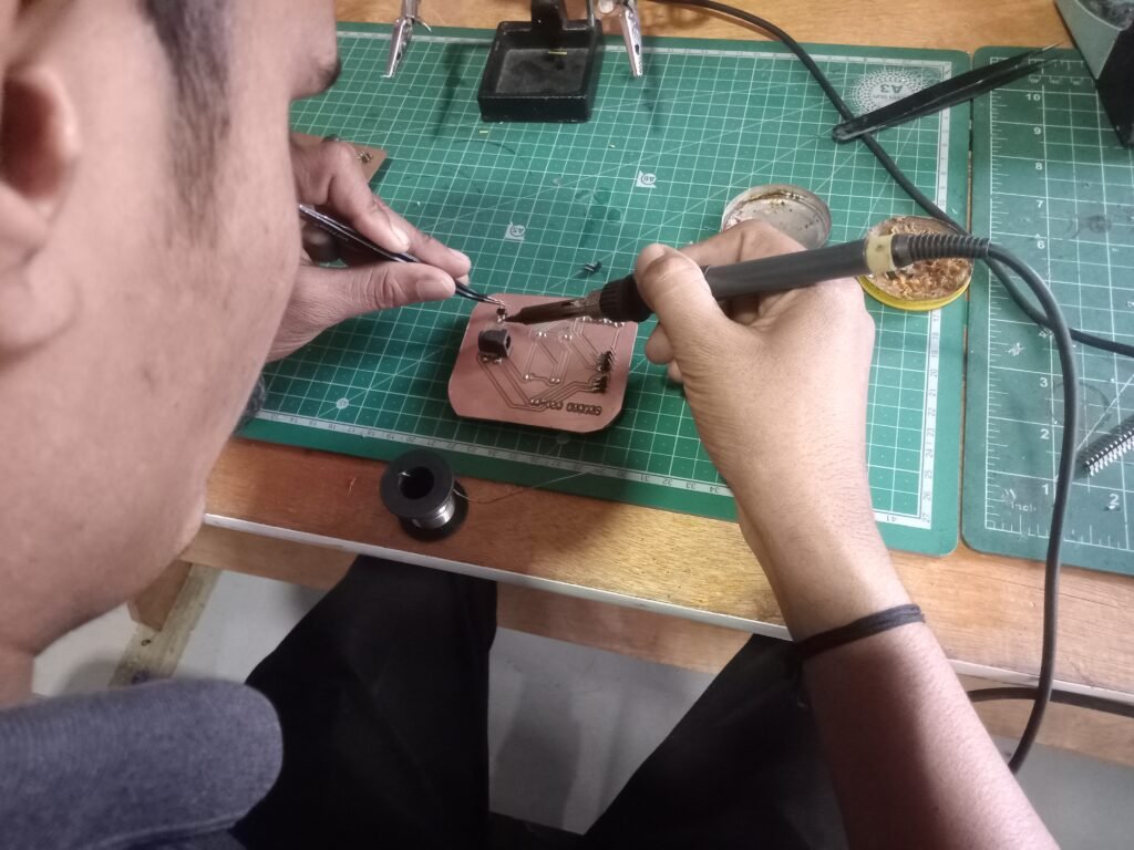
then later a pcb was designed
Conclusion
I learned how to design pieces on different 3D softwares such as SolidWorks, Fusion 360, 123D, Google Sketchup, Coraldraw and Eagle.


