
Introduction :
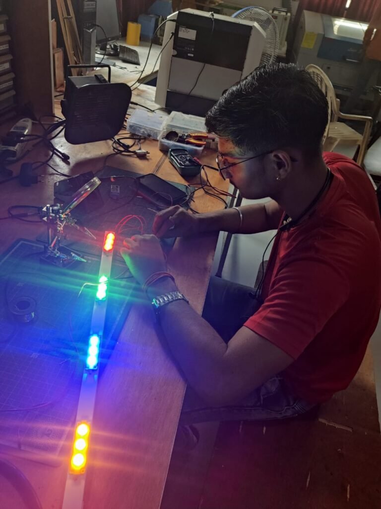
I have work on the project of running light, which was explained below 😇.
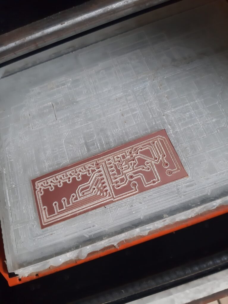
I design the PCB first, then I cut it, and then I use a tool (hand drill) to drill it.
I have to attach the component using the given circuit schematic following the drilling procedure.
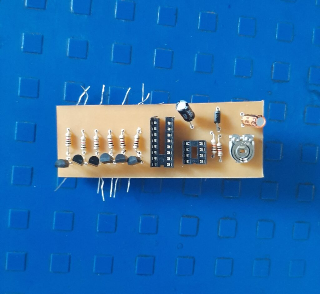
Then I need to solder every component listed below :
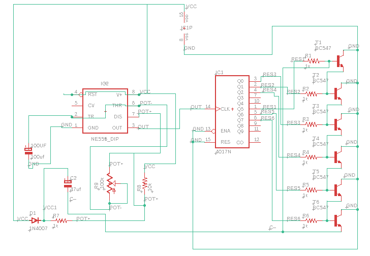
- BC547
- 1k Resistor
- 10k Resistor
- 100k POT
- IC 4017
- 555 timer IC
- 1N4007 diode
- 100uF and 47uF capacitors
After the soldering process our PCB is now ready to test 🤩🥳. After checking the PCB twice and one more, I discovered that the polarity of our diode was reversed. I changed the polarity and checked the PCB once more, but the problem persisted🤔. The issue was that since LEDs do not blinking when we turn on the power, they remain on.
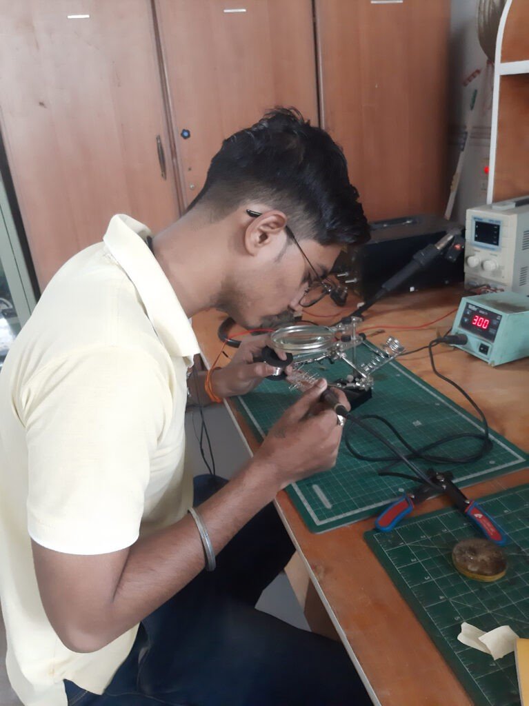
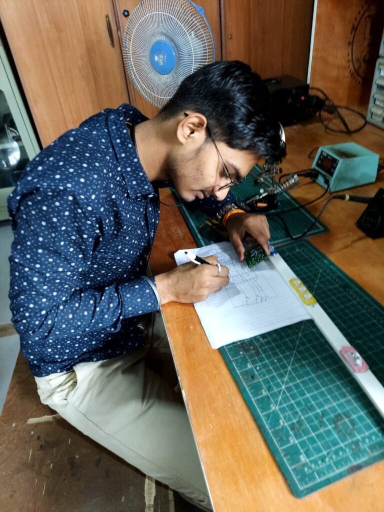
I made the decision to test the circuit on a breadboard and for that I start to tracing the circuit schematic on paper using the model available in the market.


