- PROBLEM STATEMENT :
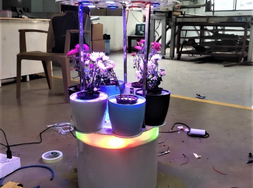
To design a hydroponics system for the Shevanti plant to present it as a gift for interior decor.
- OBJECTIVES :
- The system designed should be aesthetically pleasing.
- It should be easy to use.
- It should be detachable so that it could be transported easily.
- SYSTEM SELECTED :
Out of all the available hydroponics systems, a flood and drain (F&D) system was chosen.
- REASON FOR SELECTING F&D : The trials taken for Shevanti in F&D hydroponics systems showed better results as compared to other hydroponics systems, so we selected flood & drain method to design a system.
- VARIOUS DESIGNS PROPOSED :
1. VERTICLE SERIAL SYSTEM

2. ALTERNATE VERTICLE SYSTEM :

3. CIRCULAR SYSTEM :

4. STAIRCASE SYSTEM :

Out of the above designs proposed – a circular system was chosen.
- Reasons for selecting this system :
- Considering aesthetic point of view it was a better designed proposed.
- Ease of Fabrication.
- Ease of Functioning.
- Ease of Mobility.
- Compactness.
- Modularity.
- Material availability.
- PROCESS FLOW DIAGRAM :

- DETAILED PART LIST :
| Sr. No | Material | Quantity |
| Electronics | ||
| 1 | LEDs | 15 |
| 2 | Wire | 3 meter |
| 3 | Wire | 1 meter |
| 4 | Top pin | 1 |
| 5 | Adapter | 1 |
| 6 | 14W water pump | 1 |
| 7 | Arduino Nano | 1 |
| 8 | Relay | 1 |
| 9 | Jumper wires | |
| Fabrication Material | ||
| 10 | MS Sheets | 4*4 ft |
| 11 | Acrylic Sheet | 34*34*0.4 cm |
| 12 | Nut& Bolt | 5 mm |
| 13 | Cups | 6 |
| 14 | Outlet drip cock | 1 |
| 15 | Rubber Leg | 4 |
| 16 | Flexible Pipe | 5ft |
| 17 | SS Tube | 5ft |
| 18 | 8 mm drip fittings | 6 |
| 19 | Jointer | 1 |
| 20 | 16mm T fittings | 2 |
| 21 | 16 mm rubber fittings | 2 |
- BILL OF MATERIAL
- HAND SKETCHES OF THE SYSTEM :
- CAD MODELS :
ASSEMBLY OF THE SYSTEM :

- FABRICATION :

- Upper plate, base plate, middle plate and bottom structure were cut using plasma cutting machine..
STEPS FOR PLASMA CUTTING :
- Prepare CAD Models in SolidWorks.
- Convert .sldprt files to dxf file.
- Cut the required part.

- The upper LED plate was acrylic sheet of 4mm. Mandella art design was engraved on this to make it aesthetically pleasing.

- CONCEPT AND WORKING OF THE SYSTEM :
- Dosing solution is added in a reservoir of 15 liters. For this system I have used bucket as a reservoir.
- 14 watt water pump is used to lift the solution from the bucket into the cups. A flexible pipe of 16 mm is used for this purpose.
- The flexible pipe is connected to a circular manifold of pipe via jointer.
- By using drip connectors, solution flows from the circular manifold into the cups.
- Water pump remains on for 5 mins and after it turns off solution is drained from the cups.
Problems identified during testing:
As it is a circular manifold the first cup used to get filled very quickly as compared to remaining cups. Due to this the last cups remained half filled. If we keep the water pump on for 5 mins this lead to overflow.
SOLUTION PROVIDED :

- To solve the problem of overflowing I have provided siphon to each cup.
- When the water goes above the siphon height, siphon is activated and water starts draining through the siphon pipe.
- This siphon mechanism helps in maintaining constant water level.
- Now if the pump is on for five minutes , water level is maintained in each cup and thus plants get required nutrients.
- Water drained from siphon gets collected in a plate which is fabricated in concave shape, thus water get accumulated at the centre of the plate.
- Galvanized Iron pipe is used as a drain pipe. Water accumulated at the centre gets drained out through this pipe back into the bucket.
- A drain cock is provide to the system so that when user has to drain all the water out of the system it would be easy for them.
WATER CIRCULATION DIAGRAM :

PIPING SYSTEM AND WATER CIRCULATION :
- Considering aesthetic point of view, main challenge while designing the system was its piping .
- Target was to hide all the pipings and if there are leakage issues they should be easily identifiable.

- Drip pipe of 8mm are used to circulate the water from manifold into the cup.
- Drip connectors are used for connecting drip pipe and the flexible pipe.
WATER CIRCULATION VIDEO :
ELECTRONICS OF THE SYSTEM
- Pump should be on for 5 minutes after every 1 hour of duration. This water circulation is automated by using arduino and relay.
- LEDs need DC supply for functioning so 12V, 5A adaptor is used.
CIRCUIT DIAGRAM :

CODE :
- Final System Pictures :
- System Trail :
- Dosing of the system was done for 10 litres of water.
- The system was under trial for about 14 days.
RESULTS OF THE SYSTEM WERE AS FOLLOW :

- REASONS FOR SYSTEM ISSUES :
- Internal unseened leakages of water were observed in the system.
- The electronics of the system was placed openly, it didnt had casing. As there were leakages, electronics came in contact with the water and this lead to damage of adapter as well as arduino.
- As the electronics got damaged, water circulation system stopped and plants didnt recieve the nutrients and as a result got dried up.
POSSIBLE SOLUTIONS :
- Removing leakages of the system. This can be done by simply applying araldite or m-seal.
- Electronics should be provided proper casing.
- Relocating electronics at a place where it won’t be in contact with water.
CUSTOMER FEEDBACK :
On the scale of 1 to 10, customer Dr. Arun Dixit rated the mechanical system as 8.5 .


