Objective
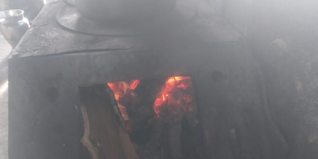
Our main objective is to solve smoke problem in our kitchen due to burning wood in wood stove. Our main objective is to reduce smoke by using different methods like working on our kitchen chimney, providing heat to wood by heating torch & maintaining roof ventilation through Turbo ventilator.
Smoke Causes:
While burning the wood, the reason it causes smoke is as follow
- If wood has moisture content in it, then while burning it causes smoke.
- If wood is burning is insufficient oxygen, then it can cause smoke.
Project Work
We did first discussion related to this problem on date 3 January 2022, Monday. In that discussion , we discussed smoke causes & ways to reduce it. We discussed Ideas as follows.
- To provide initial heating to the wood so that its moisture content can be reduce & can reduce smoke.
- To design chimney.
- Fix fan at the top of chimney.
- To uncover turbo ventilator & do necessary maintenance if required.
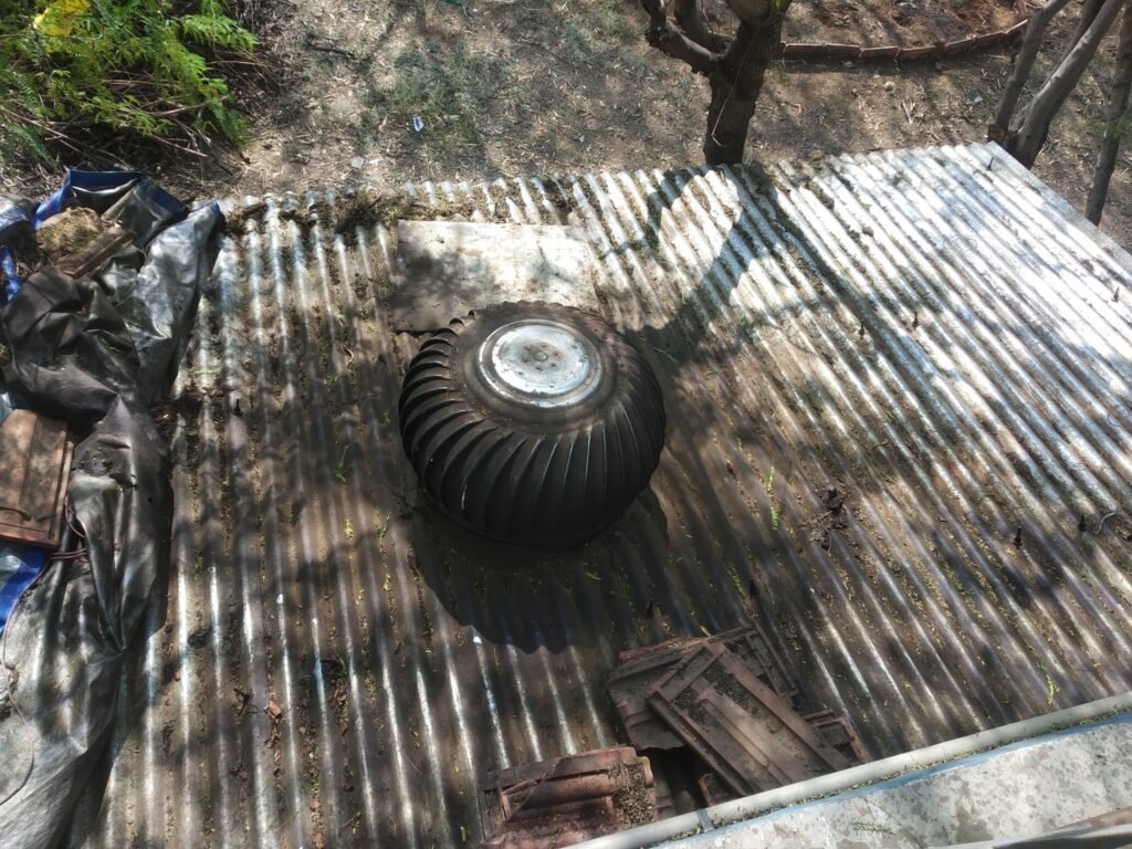
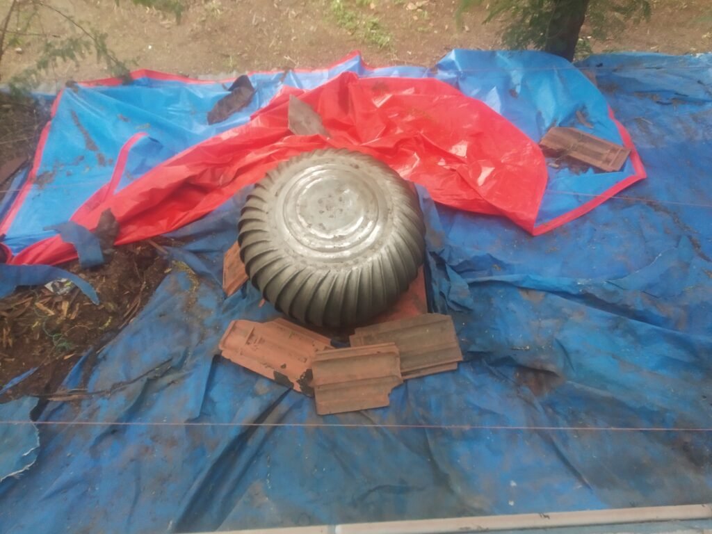
After that, on 8/1/2022, we uncovered turbo ventilator which was fixed on our kitchen roof wall. The turbo ventilator was covered more than a year because rain water was coming inside. The turbo ventilator’s now’s condition is as follows. After rotating turbo ventilator by hand, we came to know that Turbo ventilator is difficult to rotate. So its necessary to make it free.
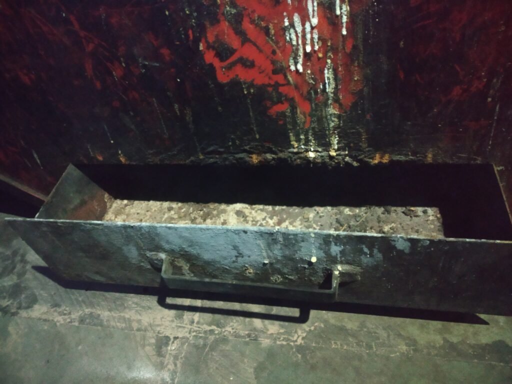
Then we cleaned wood stove’s tray where ash gets collected.
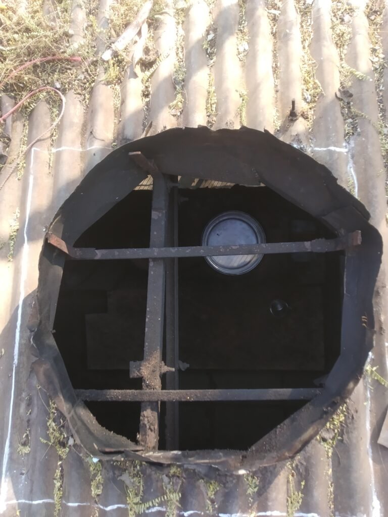
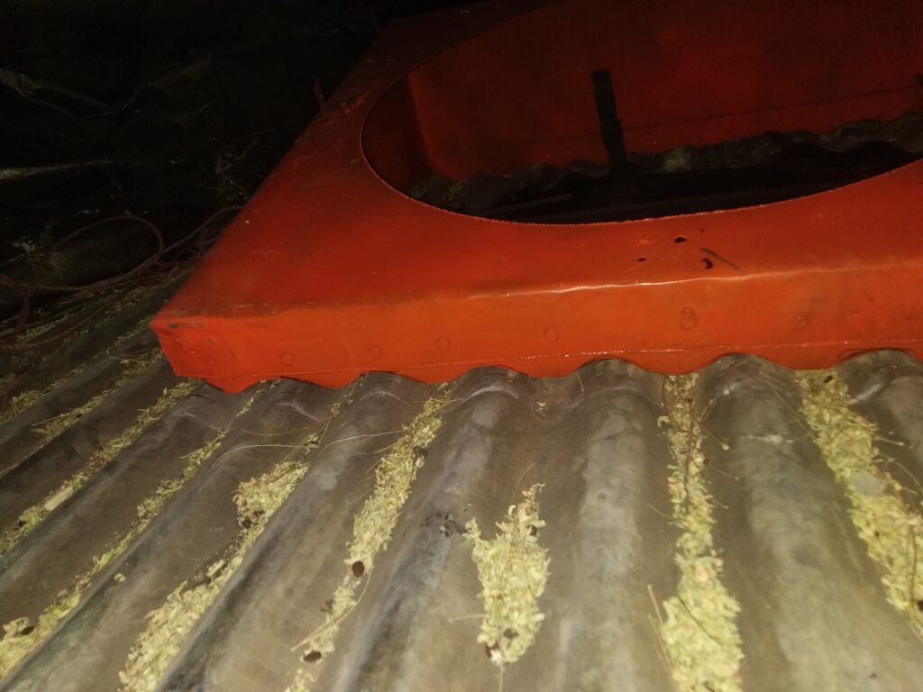
Then we applied WD40 in rotating bearings to remove rust & for easy rotation. But even after that , turbo ventilator rotates so tight. After examining, we came to know that, the kitchen roof is stucked in the bottom of Turbo ventilator as shown in figure.
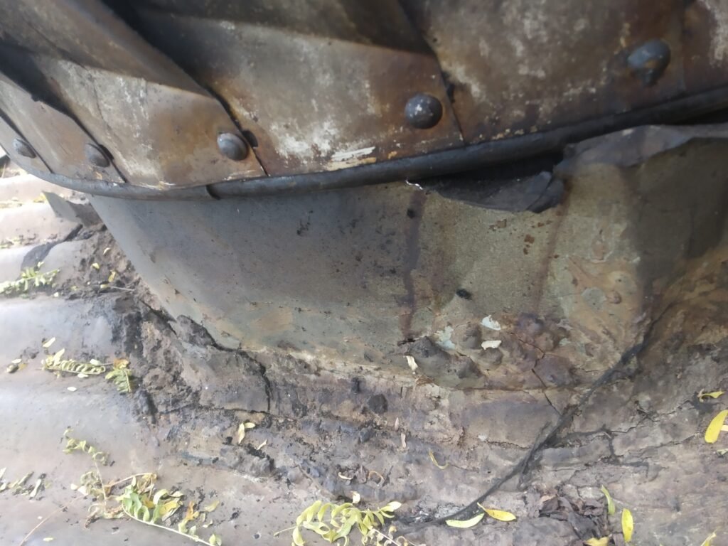
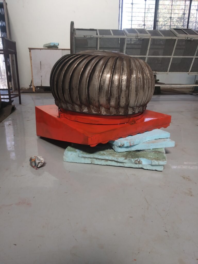
so for this, we are designing mounting for the ventilator. The turbo ventilator with mounting looks like this.
Our tasks in this project
- To design chimney for wood stove.
- To maintain turbo ventilator & provide roof for the ventilator so water won’t leak through it.
- The system to provide heat to wood.
Date 11/1/2022
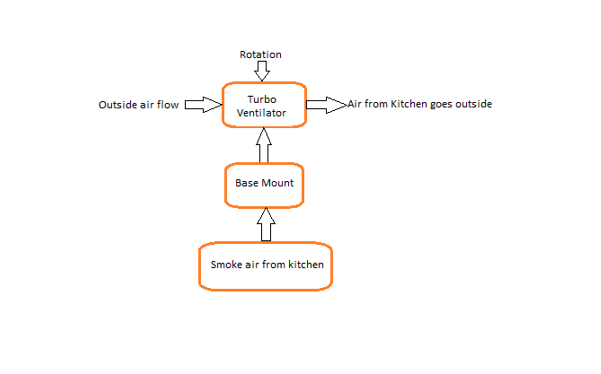
The process flow diagram of Turbo ventilator with base mount should be like this
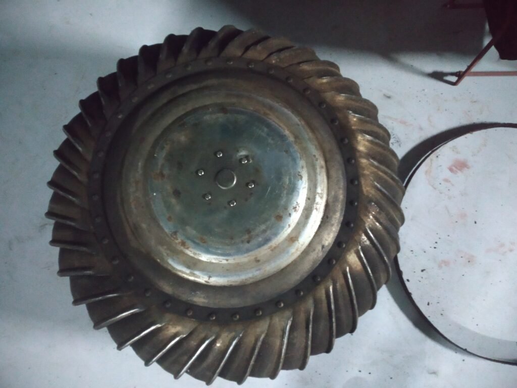
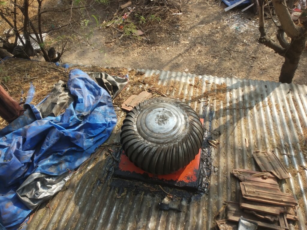
Today we removed turbo ventilator from our kitchen roof. It is necessary to clean it . It’s current situation is as given below.
Our another work is to construct chimney for kitchen . Our current kitchen chimney is as follows.
Measurements of chimney are as follows:
We did enquiry in market for pipes required to make kitchen chimney.
| Sr. No. | Name | Rate |
| 1 | G. I. Pipe | 600 rupees per foot |
| 2 | M. S. Pipe | 700 rupees per foot |
Date: 12/01/2022
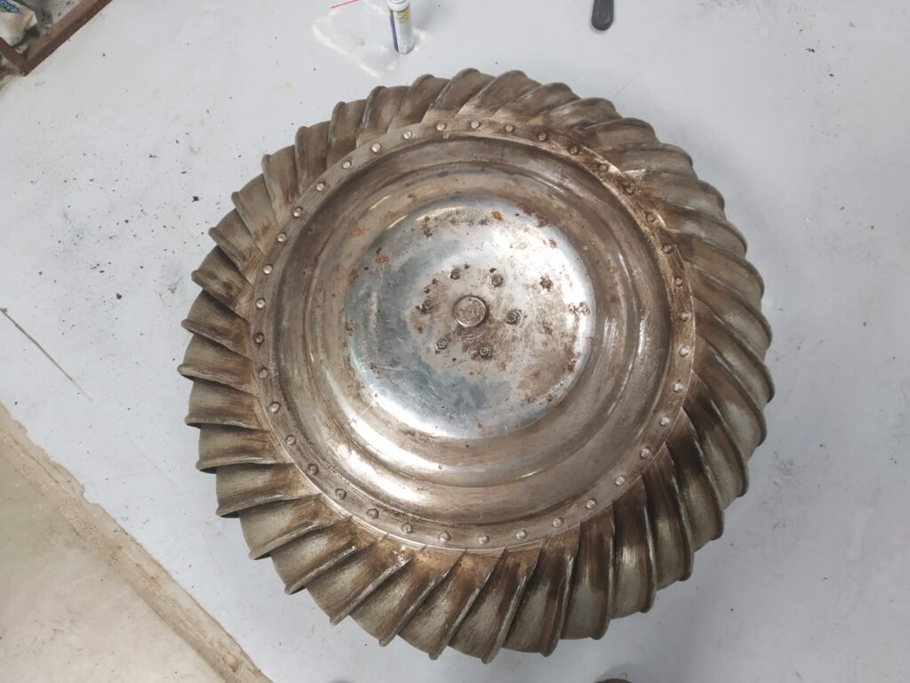
Today cleaned turbo ventilator with turpentine. Applied WD40 & Grease on bearings. Now turbo ventilator is rotating freely.
Please go on video link given below to see current Turbo Ventilator condition.
https://drive.google.com/file/d/1kRfCxutX3tIZr3QJ_nVyuPmioVtVfyTB/view?usp=sharing
Our next task is to design base mount for turbo ventilator.
Date 13/01/2022:
After discussion with Dixit sir & Prasad sir, we came to know that it is necessary to consider the relation between Throat diameter & Length of base mount to maintain air volume inside turbo ventilator. After searching we got some data of relation between Throat diameter & total length from hvac express. It’s link is given below.
https://drive.google.com/file/d/1kPyXQ6wRQGVplpi67Jq0gsJf_dnhg1-u/view?usp=sharing

Also screen shot of required data is as above.
Date: 15/01/2022
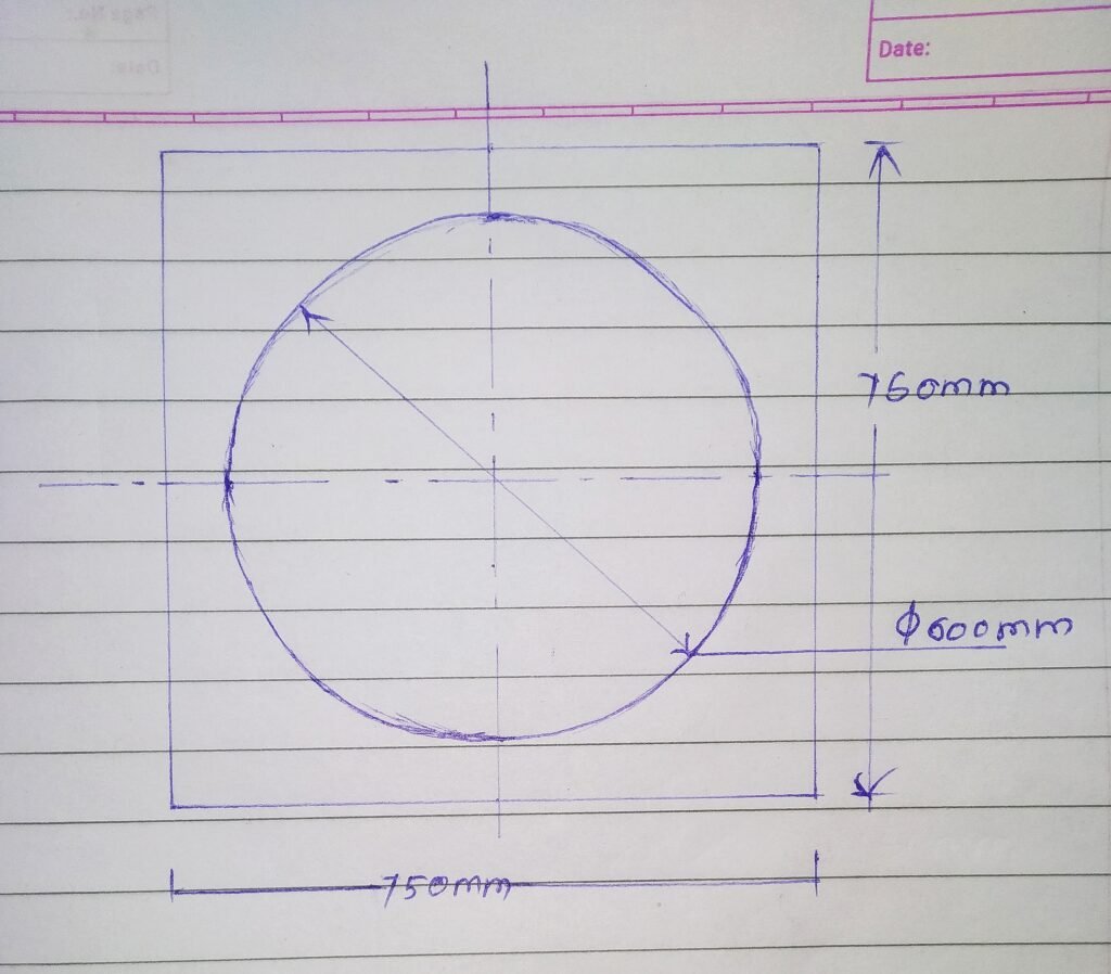
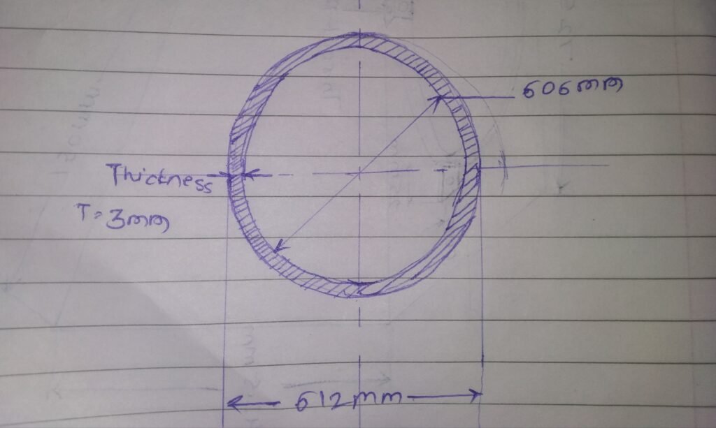
Diameter of throat ring : 610 mm
Total vertical length of turbo ventilator without is 33.5 cm. So length of base mount is 21.19 cm.
So considering cylindrical base mount on flat surface our volume is : 3.14*650mm*650mm*219mm= 70,314cm^3
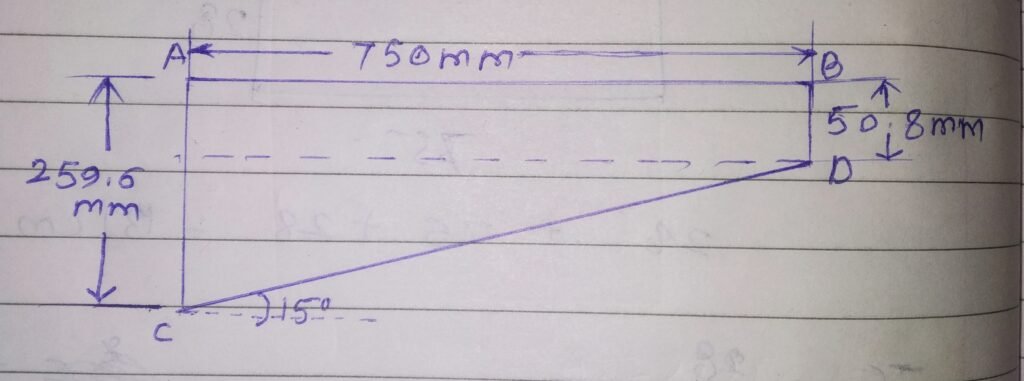
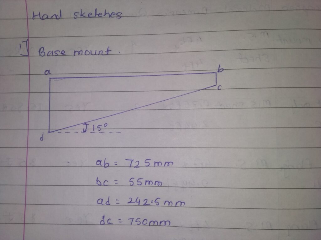
Our kitchen roof is tilted at 15 degree & our exhaust needs to be stand straight. So for this we need to make modifications in our kitchen duct from lower side so it should stand vertical.
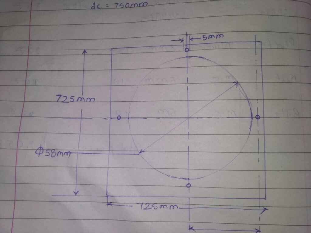
We take base mount upper dimensions as 750 mm * 750 mm square.
Date 22/01/2022:
After discussing with Prasad sir ,considering volume of 71314 cm cube & for fabrication suitability, we zero down on below shape structure.
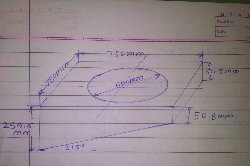
| Sr.No. | Volume we required | Volume we obtained |
| 1 | 70,314cm cubic centimeters | 88,189 cubic centimeters |
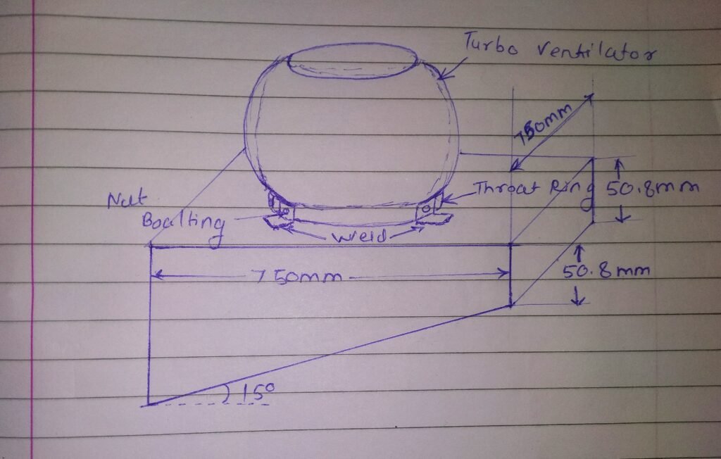
Complete assembly should look like this.

Date: 23/01/2022:
In today’s discussion with Dixit sir & Prasad sir, we discussed various ideas for our kitchen chimney. We discussed about ferro cement chimney. For this we need chicken mesh & cement.
We also discussed about making duct as chimney. For this, we considered M.S. Sheet & did market survey for M. S. sheet.
Please click on link given below to see part list.

Also screenshot of part list is as above.
Date: 24/01/2022
Today we did market survey for Turbo ventilator base mount. For today’s market survey, we used contacts from India mart. Our main concern about Turbo ventilator base mount is, it should adjust with roof angle & also should accommodate with roof gaps. But we couldn’t fix that, the turbo ventilator from market can fulfil our requirements & price is high too.
Also did market survey for M.S. Pipe by using India Mart contacts for our kitchen chimney. But pipe dimension were not matching. it’s price & weight is another reason we cannot go with market M.S. Pipe.
Market Survey
Please click on link given below to see market survey list. https://docs.google.com/spreadsheets/d/1bo_biPO3DjBjKWMEIi9IZAkyehg7_k47/edit?usp=sharing&ouid=102509193490900660230&rtpof=true&sd=true

Part List
please click on link given below to see part list.
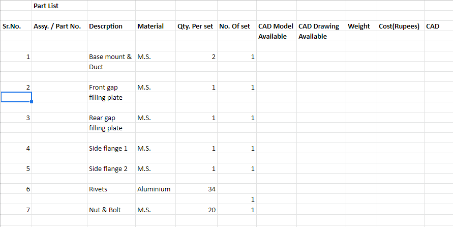
Also, screenshot of part list is as above.
27/01/2022:
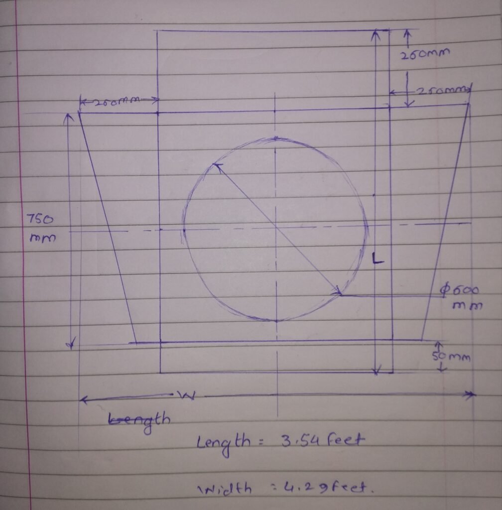
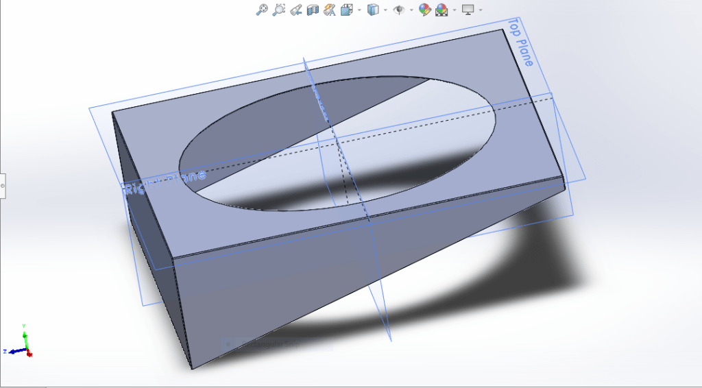
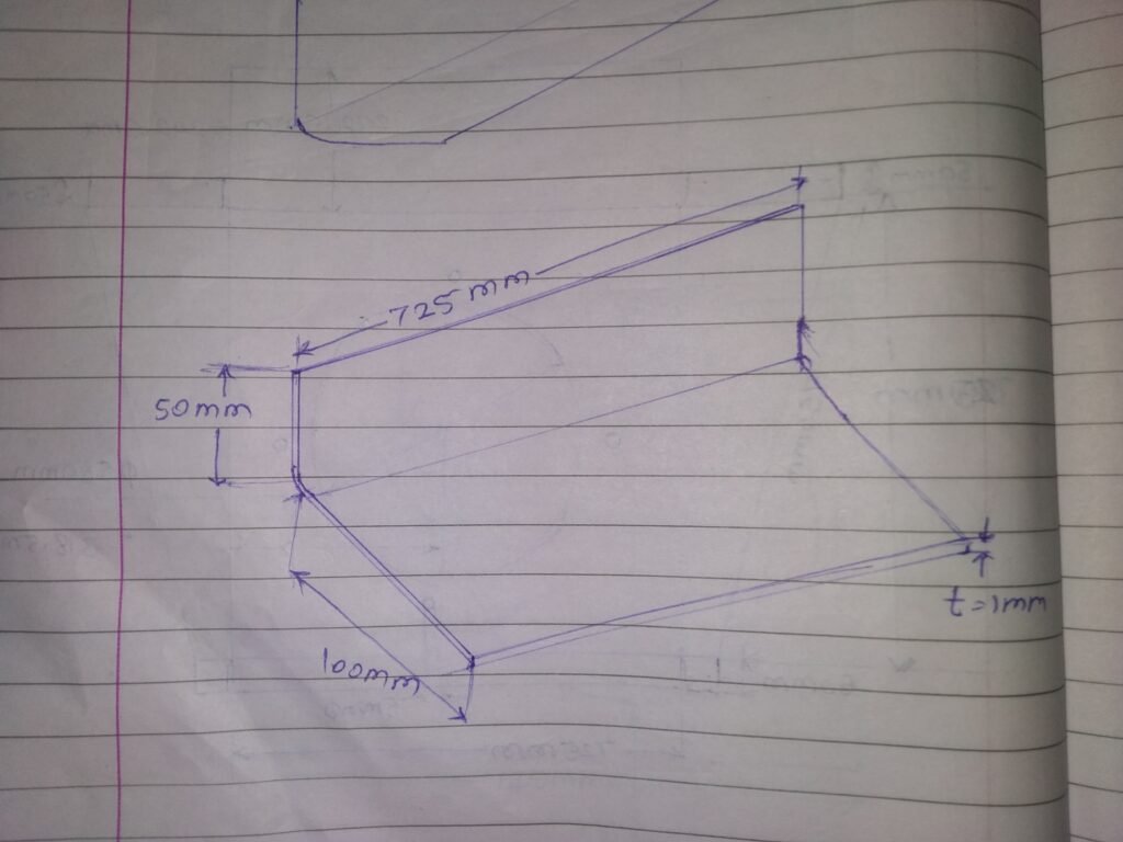
Today, redesigned turbo ventilator base mount for volume and actual material dimensions.
Our new base mount should look like this
To fix throat ring on turbo ventilator, we need some fittings.
Throat ring dimensions are shown as below.
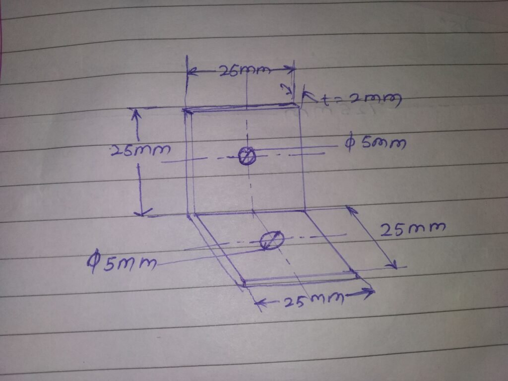
Dimensions of fittings to fix throat ring are as below.
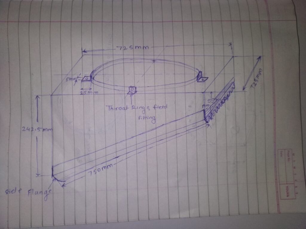
Fittings to fit throat ring on mount base is as follows.
Date: 28/01/2022
Today, marked Turbo ventilator box position as shown in figure.
From this, we can say that our dimensions are correct box can fix over the opening.
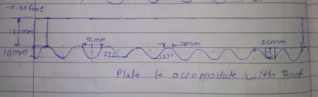
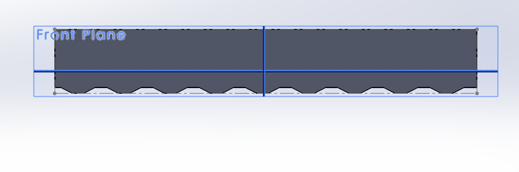
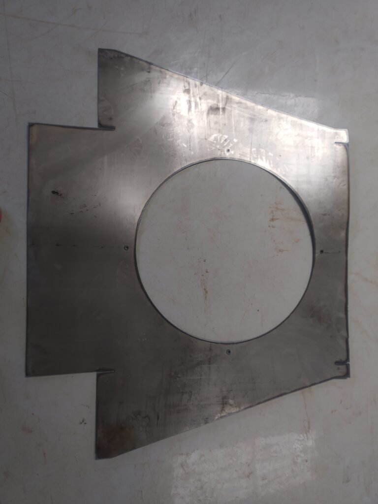
Our kitchen roof is not plane, it has wave structure. So to fix with this, we need to design two plates for front side and rear side to accommodate with roof and to fill the gap. These plates looks like this.
Also side flanges at both sides needs to be fitted. To fix the box from both side, we need to design side flanges, as roof is no plane surface.
Design of both side flanges is as follows.
After assembling, the final diagram is as follows.
CAD Drawings


Final Assembly
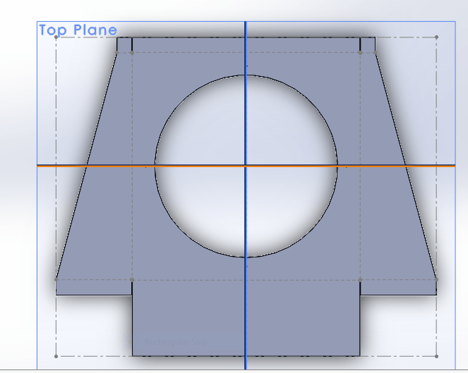
Date 3/02/2022 : Today cut flatten shape of base mount on M. S. Sheet as shown in figure.

Date 5/02/2022 : Today by using bending machine, made the desired base mount shape and fixed its ends by using rivets as shown in figure.

Date 6/02/2022 : Applied red oxide on base mount and throat ring as shown below and let it rest for 6 hours.
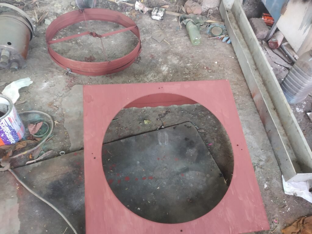
Date 7/02/2022 : Applied paint on base mount and again let it dry for six hours.
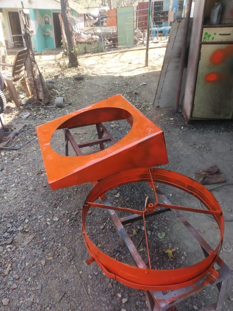
Date 8/02/2022 : After applying red oxide and paint on the base mount, we assembled base mount with turbo ventilator.
Our next task is to fix base mount on kitchen roof. Today we placed base mount on kitchen roof, but the front and rear adjustable plates are not fixing properly. Some curves are fixing while some are maintaining gaps. So next task is to grind front and rear plates curves to fix base mount on roof.
Date 9/02/2022 : After grinding the curves, according to roof, base mount fixed on kitchen roof.
Date 12/02/2022 : Fixed the base mount on kitchen roof by using cement. After cement put one jeans cloth pieces on each cement side and applied tar coal on jeans.
Date 20/02/2022 : Today we found that, tar coal is melting and leaked through the gaps. So today removed all the tar coal and cement from the kitchen roof and for now removed base mount from the kitchen roof.

Date 22/02/2022 : Today with Dixit sir & Prasad sir, discussed about sealants for base mount ventilator.
After discussion, we came across ideas are as follows :
- Plaster of Paris
- White Cement
- Regular Cement
- Dr. Fixit
Date 23/02/2022 : After talking with vendors who supplies above materials & few people who have working experience, we discussed finalized to use ‘Asian Paints True care Knifing paste filler’ (Metal Putty) to fix the base mount over roof.

Date 24/02/2022 : Chimney Dimensions. Our kitchen chimney dimensions are as follows
Chimney Pipe Diameter: 165.5 mm Flange Diameter : 210.9 mm
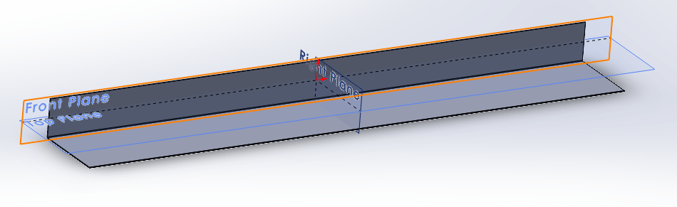
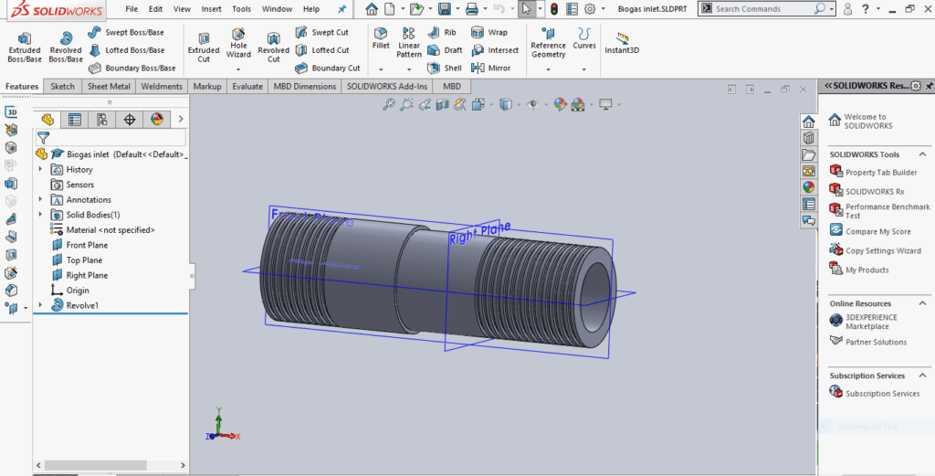
Now, our next task is to design duct for our kitchen chimney. For that, we need to keep our flange dimensions as it is & need to design new duct .
New duct dimensions: 122mm*116*h
New Flange dimensions
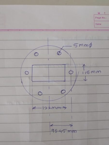
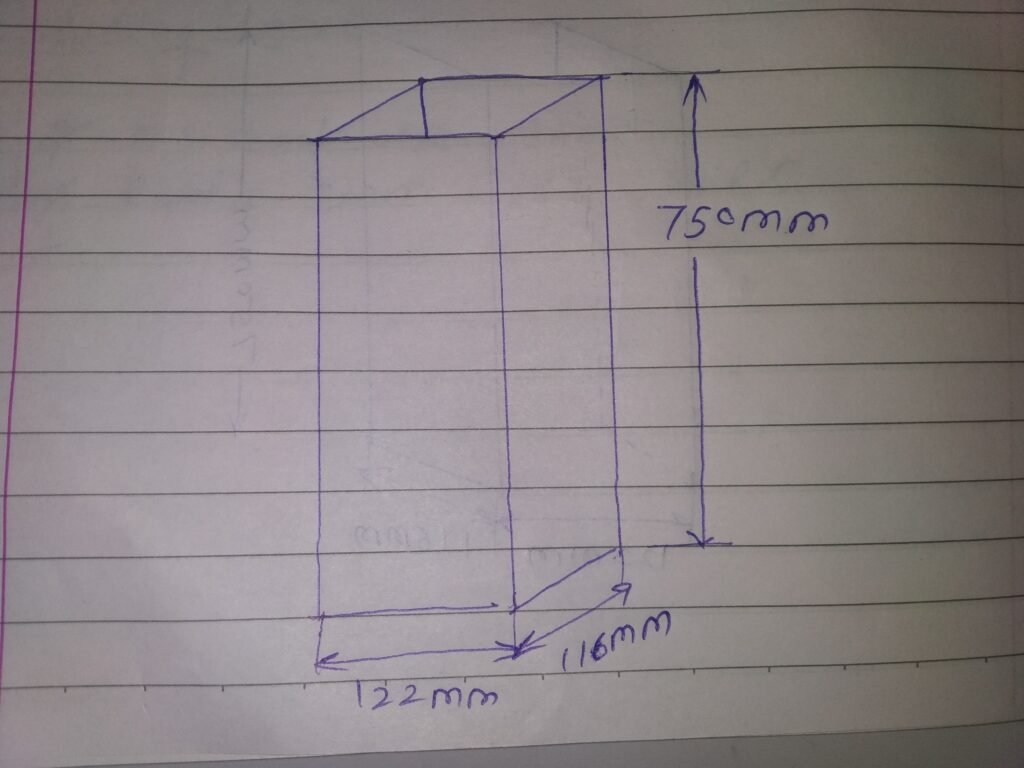
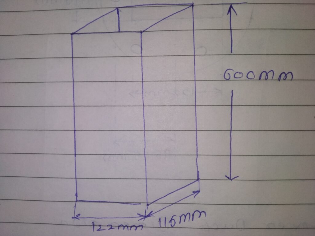
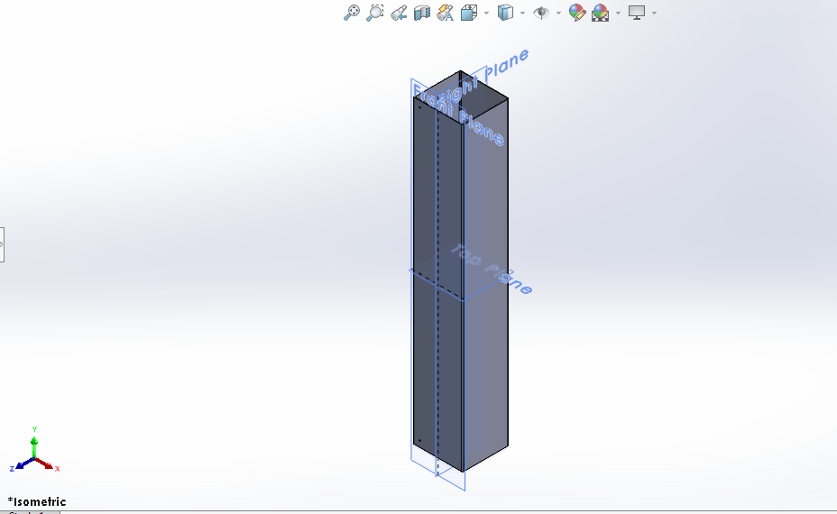
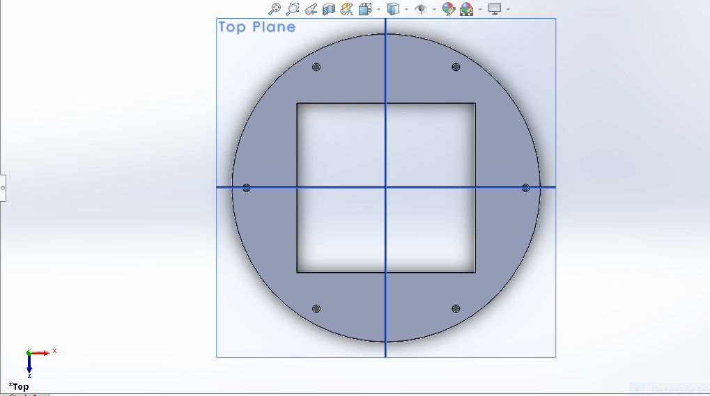
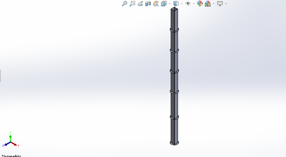
Solid works for duct is as follows:

Date 27/02/2022: Today first, cleaned kitchen roof surface. Placed base mount over the roof hole and applied metal putty on four corners and at front front side of base mount.

Costing
Please click on link given below, to know costing of base mount.

Date: 8/03/2022
Today took water leakage testing by pouring water on one side of base mount. But even after applying metal putty, we failed at water leakage test. So from this, metal putty is not applicable here.
Date: 16/ 03/2022
Today after discussing with Prasad sir, we decided to use FRP ( Fiber reinforced polymer ) to fix base mount as well as to prevent leakage.
How to make FRP?
To make FRP we need following materials:
Glass Wool (to give shape)
General purpose resine.
Hardner
Cobalt.

Procedure: While preparing FRP, we need place Glass wool sheet in the required shape. Then the mixture of resin, cobalt, hardener is applied on glass wool & then it is allow to dry.
Proportion of Resin, cobalt & Hardener.
| 1 Liter resin | 10 to 15 ml hardener | 10 to 15 ml coblat |
In above proportion, we prepared solution & applied on on glass wool & let it rest.
Date: 8/04/2022
Today again, we took water leakage test. But this time also, water went inside kitchen .
After talking with FRP material suppliers from pune we came to know that, chalk powder is the ingredient which fills the gap.
Date: 12/04/2022
Today, mixed resin with chalk powder till it forms thick paste. after forming it’s thick paste, mixed hardener & cobalt in the same proportion & let it rest.

Date: 13/04/2022
Today again, we took water leakage test & this time, water didn’t go inside kitchen instead of this, it remains on the roof. From this came to know that, while preparing FRP leak proof composite, Chalk powder is the main ingredient.
Date: 07/06/2022
Roof where base mount was fixed had gaps causing water leakages. full roof was packed with plastic which covered turbo ventilator also. So cut the plastic & made pocket for turbo ventilator as shown in fig.
In continuing this project, we searched options to reduce smoke & the cause of wood smoke. In smokeless chulhas or stoves wood needs ample amount of oxygen to burn so the burn properly causing less smoke.
- We’ve smoke-less wood stove in our kitchen but not enough big space to burn woods properly. So if wood get maximum heat intense heat they’ll burn properly causing less smoke.
- We’ve floating biogas tank in our campus at kitchen back-yard. We use cow dung & our daily kitchen wet waste to produce biogas. We’ve biogas stove in our kitchen which has inlet to enter biogas. The problem we’ve to maintain continuity in biogas supply to biogas stove inlet through pipe which has direct connection from biogas tank.
Our main objective to solve both these above problems.
To solve the problems first examined system & collected details of system.
- Tank details:- Tank dimensions,
- Diameter:- 2 meter
- height:- 1 meter
- thickness of tank walls:-8 mm
- Area of tank:- 3.14*100cm*100cm= 30,899.6 cm^2
- volume- area*height= 30,899.6 cm^2 * 100 cm= 49,832 m^3
- weight- Tank circumference:- 2*3.14*100cm=622.976 cm
- Density:- 7870kg/m^3
- Extra weight over the tank lid:- 198 kg Density= mass/volume 7870kg/m^3=mass/0.049832m^3 Therefore mass=392.177kg (mass of biogas tank)
- Total load on Biogas :-392.77kg+198kg+ 590.177 kg
- Pressure on biogas in steady position:- force/ area 590.177/30899.8=0.019099kg/cm^2
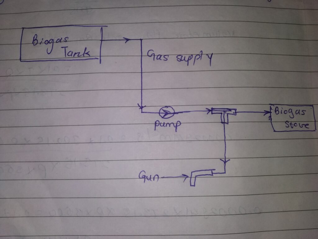
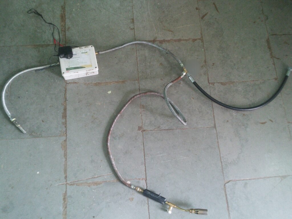
- Now we need to design system to provide biogas to the biogas stove & to provide heat to the wood as shown in figure.
Date:- 09/06/2022
To provide heat to the wood in wood stove.
After discussing above (1) & (2) problems with Dixit sir & Prasad sir, we came to point to do experiment with biogas.
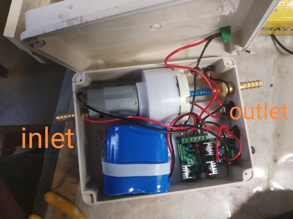
We have one pump module which is suitable for biogas
Date:- 16/06/2022
System details
Motor details:- 12 volt dc , 1.03 Ampere
Battery:- Lithium phosphate batteries, 12.8 volt, 1amp hour
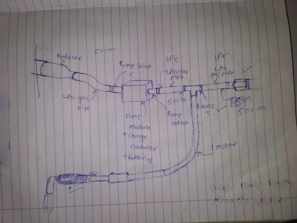
We need to design system by using this pump & existing biogas connection.
Date:-17/06/2022
Date:- 18/06/2022
Collected information of parts required for above design. For this, I took help of Mr. Shubham Jadhave who runs gas stove repairing shop in Pabal.
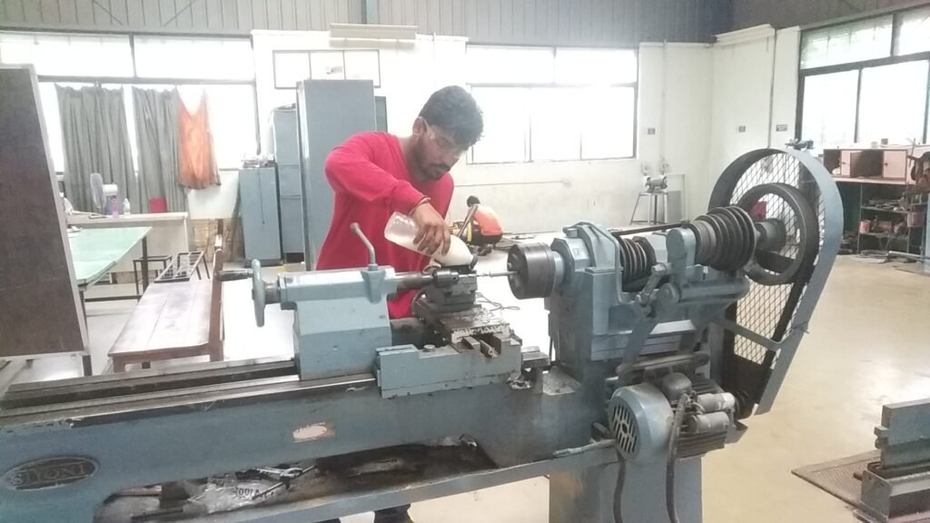
Date:-23/06/2022 To supply biogas in pump inlet, we need to provide some connection at pump inlet. We visited CNC shops in Chakan MIDC to prepare this part on CNC. But the single part cost was so high.
Date:-25/06/2022 So after discussing with Dixit Sir, we decided to fabricate that part in Stainless Steel material in our workshop
Date:- 10/07/2022
Date:-12/07/2022

Date:- 15/07/2022
Date:-18/06/2022 Now as discussed I connected that system in our kitchen & took testing.
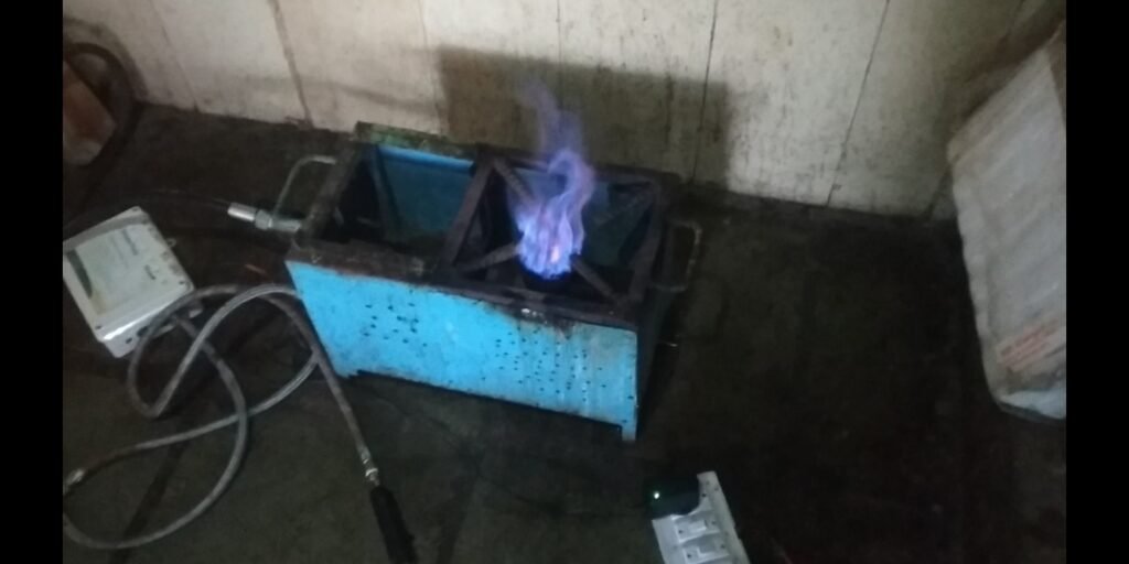
Gas gun didn’t run on biogas. There are chances of gun pressure requirements are not fulfilled due to this gas gun not burnt.
Date:- 23/07/2022 Biogas flow rate calculation when system was connected to the biogas inlet pipe. As we have floating dome biogas tank in our campus, tank height raises & reduces as gas level inside it. Volume before using V1= 3.14*1m*1m*0.16meter= 0.4943m^3
Volume after using V2= 3.14*1^2*0.12m^2= 0.3073m^3 Volume used= V1-V2=0.1236m^3
system was on for 7 minutes Therefore flow rate= 0.1236m^3/7min 0.01765m^3/min=17.65 Liters/min
Gas fluid passing through pipe has following calculations Volumetric flow actual rate (Qa) [m^3/s]= 0.1*T*Q/273.15*P*3600 where, T= Temperature (k) Q= Flow rate Nm^3/h (normal meter cube per hour) P pressure= Mpa ( mega pascal absolute)
Here, our volumetric flow rate is 17.65 liters/min= 0.01765m^3/min=0.01765m^3/60= 0.0002941m^3/second
Gas not burned. Pressure calculation To find flow rate Q from volumetric flow rate Qa Volumetric flow rate* Biogas density 0.000294m^3/s * 1.15 kg/m^3= 0.5 m^3/h
0.0002941m^3/s = 0.1*300.15*0.5 / 0.0002941*273.15*P*3600 Therefor P= 0.05191 Mega pascal Required pressure for LPG gas gun= 1.713 Mpa Obtained pressure of system=0.05191Mpa< Required pressure for LPG gas gun= 1.713 Mpa
Conclusion: Turbo ventilator was fixed on inclined roof. When base mount was designed for it to place turbo ventilator in horizontal plane, turbo ventilator sets on horizontal plane & turbo ventilator rotates continuously removes smoke & hot air in attic & kitchen space. When gas gun is connected to LPG it gives blue flame & burns the wood efficiently & also reduces smoke.

