If you are planning to install a new battery for your e-cycle or e-vehicle, it is very important to select the right battery pack for your system. You have to select a battery based on parameters such as capacity(A-hr), voltage, charging /discharging cycles, Size, safety, and fit into your needs.
I am using lithium iron phosphate cells (LiFePO4) Cell Model: IFR32700N60 of Cell Size: 32650 for making my DIY battery pack. There are many advantages of the LiFePo4 battery over other rechargeable cells in the market. which are described in detail in my privies blog on “Selection of battery for E-cycle”. we will now move from cell to pack.
In this blog, I will show you, how to make a LiFePO4 Battery Pack for applications like Electric Vehicle. The fundamental is very simple: Just to combine the number of LiFePo4 cells in series and parallel to make a bigger battery of desirable voltage and capacity.
The specification of battery build in this blog is as:
As we know I am building this battery pack for my e-cycle project. Which will use to run a 250W BLDC hub motor. The power requirement of the Driver is as described in my prices blog “Selection of battery for E-cycle” considering this we are making a battery pack of the parameter as follow :
Voltage :24v
Amp-hr:24A-hr
Battery Configuration
So, what is Battery?
A battery pack is a set of any number of identical batteries or individual battery cells. They may be configured in a series, parallel, or a mixture of both to deliver the desired voltage, capacity, or power density.
The calculation for Desirable Specification of the Battery Pack I am making is as follows.
Series and Parallel Connection
Batteries may be used in series or parallel to achieve higher operating voltages or capacities to achieve the desired requirement for a specific application.
Series Connection:
Connecting Cells in series add the voltage of the two batteries, but it keeps the same amperage rating (also known as Amp-Hours).
Example: Connecting eight 3.2V / 6000mAh cells in series will produce 24V, but the total capacity remains the same ( 6000mAh ).
Parallel Connection:
Parallel connections will increase your current rating (Amp-Hours ), but the voltage will stay the same. Ultimately you will make a single cell with a higher capacity.
Example: Connecting four 3.2V / 6000mAh cells in parallel will produce 3.2V, but the total capacity will be increased to 24000mAh.

Estimate the Required Number of Cells
To make the battery pack, you have to first finalize the nominal voltage and capacity of the pack. Either it will be in terms of Volt, mAh/ Ah, or Wh. You have to connect the cells in parallel to reach the desired capacity (mAh ) and connect such parallel groups in series to achieve the nominal voltage (Volt ).
For this project, the requirement is: 24V and 24Ah Battery Pack
Specification of 32650 Cells Used: 3.2V and 6000 mAh
Capacity (mAh):
The desired capacity of the battery pack = 24AH or 24000 mAh.
The capacity of each cell = 6000 mAh
No. of cells required for parallel connection = 24000 / 6000 =4 nos
Commonly cells in parallel are abbreviated in terms of ‘P’, so this pack will be known as a “4P pack”.When 4 cells are connected in parallel, ultimately you made a single cell with higher capacity ( i.e 3.2V, 24000 mAh )
Voltage(V) :
The desired voltage of the battery pack is 24V.
The voltage of each cell = 3.2 V
No. of cells required for series connection = 24 /3.2 = 7.5 ~ 8 nos
Commonly cells in series are abbreviated in terms of ‘S’, so this pack will be known as an “8S pack”.
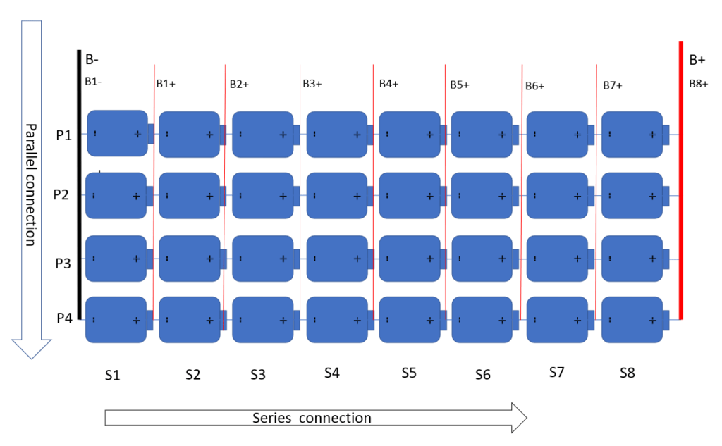
So we have to connect the 8 parallel groups (4 cells in each group of 3.2v 24A-hr ) in series to make the battery pack of 24V,24A-hr.
The final pack configuration is designated as an “8S4P pack” with a final specification of 24V,24AH.
Therefore the total no. of cells I require to make a battery pack of The final pack configuration is designated as an “8S4P pack” with a final specification of 24V,24AH =8*4=32 nos
you can follow the same steps for your designated pack configuration.
Step-By-Step 24v LiFePO4 Build Instructions:
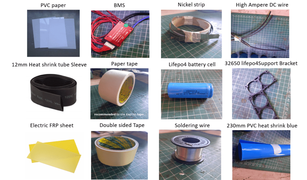
Step1:Matterial Procrastination:
To make your battery pack, you’re going to need quite a few items. They are the following:
Step 2:Tools Used :
1. Spot Welder
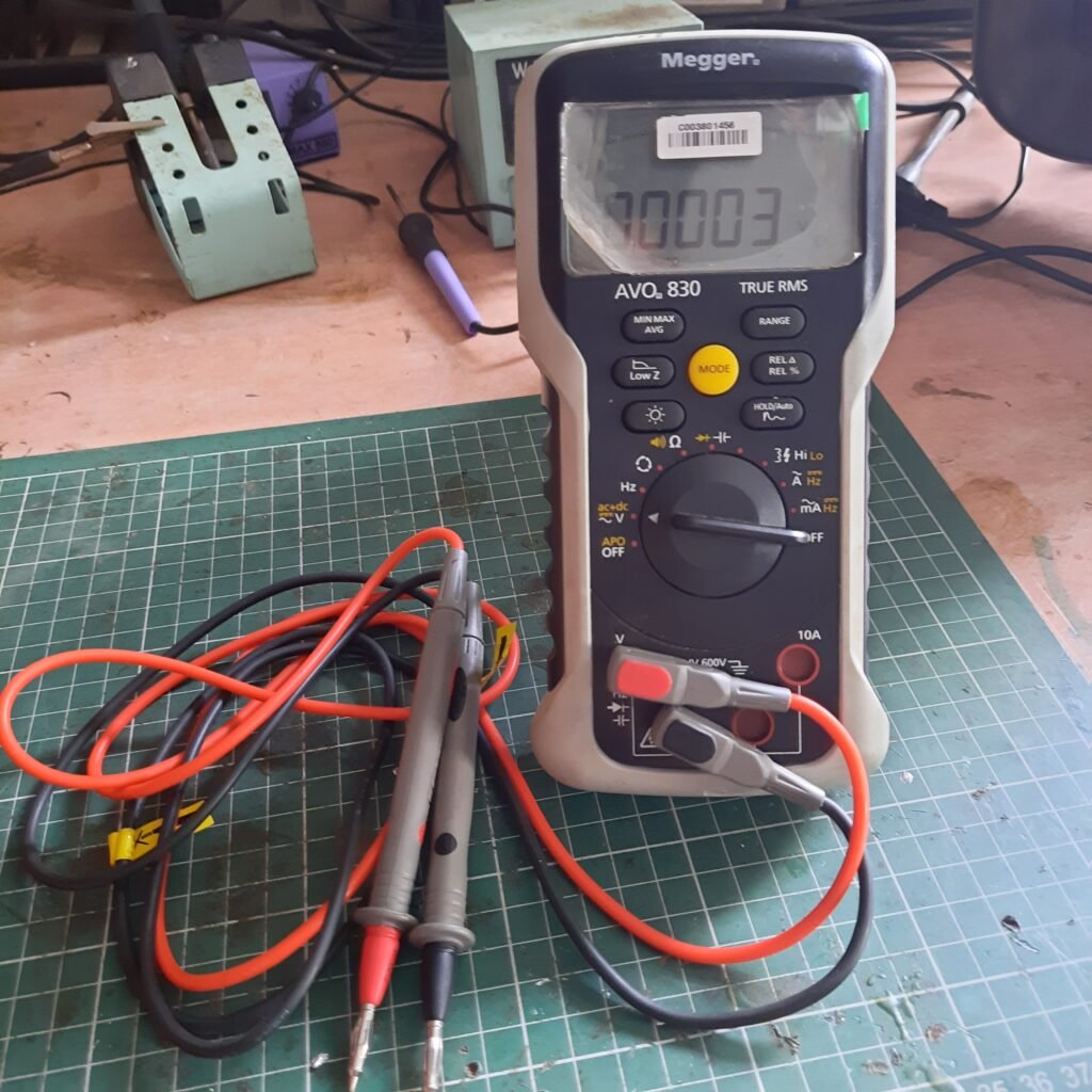
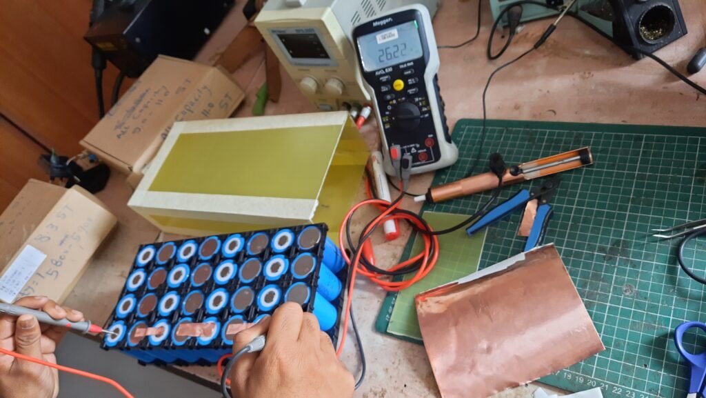
2. Multimeter
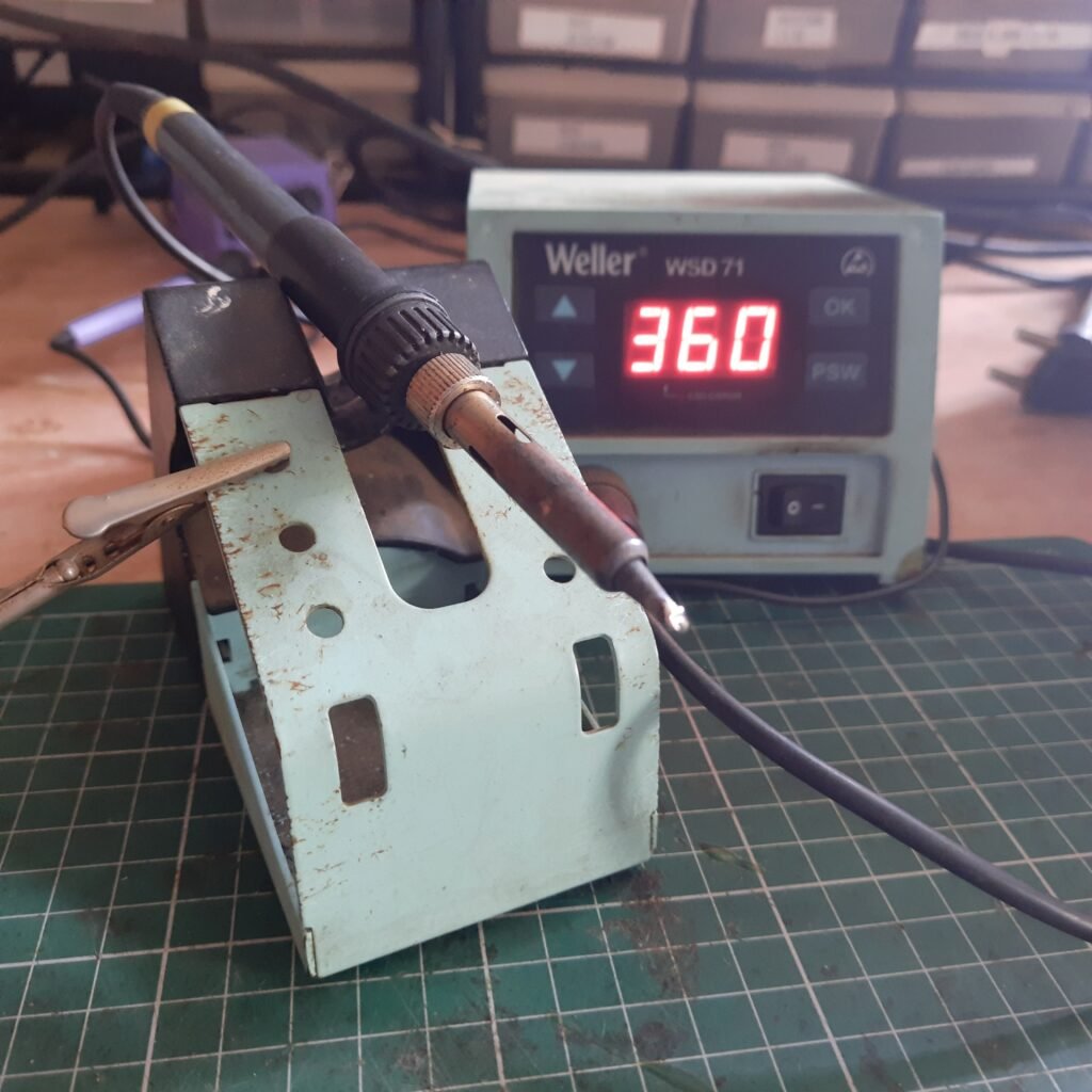
3. Soldering Iron
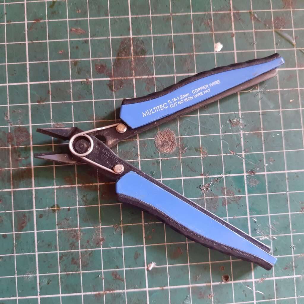
4. Wire Cutter
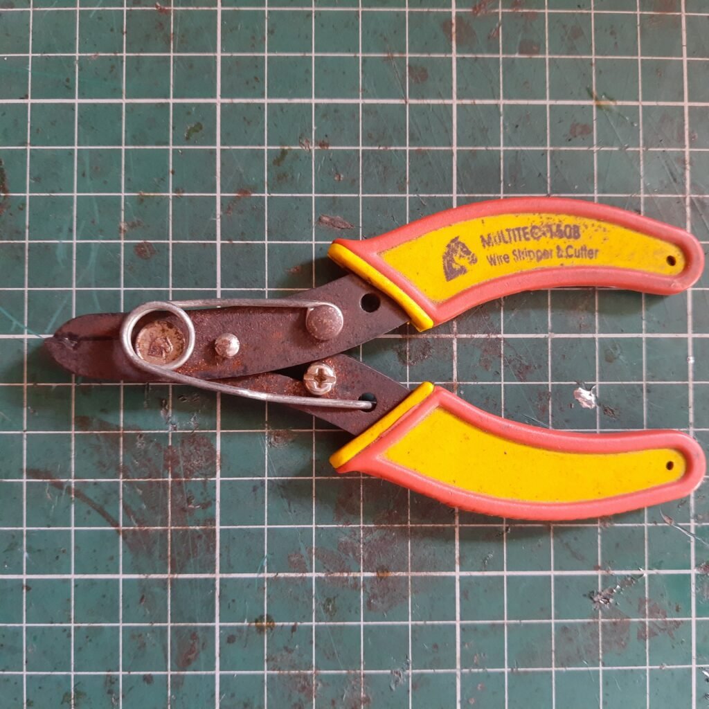
5. Wire Stripper
6. Hot Air Blower
Step 3:Segregate the Cells :
This is the most important step for making any battery. If you take this stape lightly your battery may not work at optimum capacity or may fail down before the expected time. These are some sub-stages or tests which are recemented for any battery maker to take before starting to build their battery pack. Please go through these stapes and I ensure you that your battery pack will work in an optimum way.
Step 1: Check for any physical damage of cells during shipping from vendors such as dent, a deep scratch, any type of penetration on the cell body, etc if such damage is detected it is recommended to not use it.
Step 2: chacking individual cell capacity.
In this stape cells are first fully discharged and then fully charge by using a capacity testing machine .using this machine each cell is checked for its true capacity .and according to which cells are segregated in groups that process is called cell grading.
- This is the first stape of quality chack in which we segregate cell with similer capacity.make shore each cell must have capacity near abou 6000mAh and it should not less than 5900mAh cells of this capacities are not recomended to use.
- using similer capacity of cell in battery pack increas overall efficiency of battery pack . The capacity of individual battery is proportinal to (SOC) state of charge of the cell .use of slightly different capacity cells in battery pack can result in premature discharge and charge cutoff which can result in poor performance of battery pack.If one of the String of cell in battery pack contain lower capacity cell that string tends to full charge earler than other and discharge soon than compare to other strings in battery.which will distorb the functioning of BMS and make battery performance lower than expected capacity and voltage range .
Step 3: Chaking individual cell open voltage.
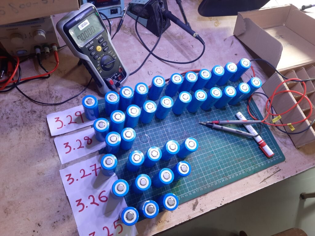
Use this guide to determine how to check your cells:
- If you check the voltage and the cells are identical or within0.05 volts different of each other, you can directly use them for next Step.
- If the cells have a similar voltage, but they are a little bit different (within 0.1 volts of each other), it is recomended that do not use them directly .
- If the cells have a large voltage difference (more than 0.1 of a volt for cell voltage higher than >3.2), you should not connect it in battery , instead discharge the higher voltage cell with a 2-3 watt, 2.7 ohm resistor/ any desired DC load . Just attach the leads of the resistor to the individual higher voltage cell, and wait till it is at a voltage that is closer to the other cells(not less than 3.2V). When they are within 0.05 volts of each other, then you can use them.
- If the cells have a large voltage difference (more than 0.1 of a volt for cell voltage lower than <3.2v), you should not connect it in battery , instead charge the cell using a proper charging circuit and wait till it is at a voltage that is closer to the other cells(not less than 3.2V). When they are within 0.05 volts of each other, then you can use them.
- Also note that it is recamended not to use cell higher voltage than 3.6v and less than 2.5v as it is higest and lowest voltage range of LiFePo4 cell other wise they are damage .
- note this all suggisection are not done by me but this are dissccus by me with LifePo4 battery manufacturers .In my case all the cells were already tested by vendar so they were within the range of 0.05 v.
Step 4: Check cells Internal resistance.
Internal resistance (IR) plays a vital role in the current flowing throw an individual cell in the battery pack. each cell has there own resistance (In milli -ohm) that resist the current flowing in the battery which affect it in various ways. Internal resistance can drop the voltage in series resulting in unexpected end terminal voltage. also, it tends to generate an unbalanced heating effect (H=I^2 *R*T)for any particular cell with slightly different resistance. which can activate thermal security of BMS result in turn-off battery and loss in battery life due to improper charging and discharging due to Slightly different resistance(of the cell) in series connection. So always try to connect the battery with similar internal resistance or make sure the cell you are using in making the battery are IR tested before using them in your battery pack.
I use to buy these cells from a local lithium battery manufacturing factory so in my case I request them to do this test in advance .this all tests take some additional cost which I consider not bad. So I will suggest going on my way and also make sure to re-examine test life open voltage and physical damage.
let’s jump on to the Next Step…
Step 4: Mechanical design considerations:
Step 1: Preparing the Cell Holders Structure:
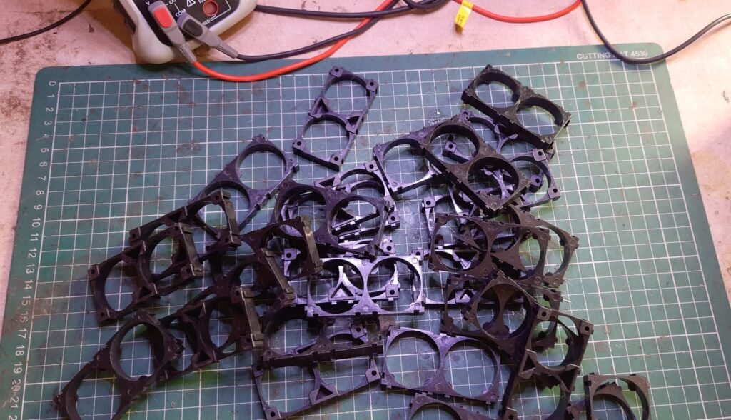
From this stage onward, the real design of the battery pack is started. In this stape, we ensure the mechanical and structural safety of individual cells and the overall battery packs. It is very important to make your battery mechanical designed especially if you’re using it for an application like EV Due to continuing. Dynamic forces acting while riding the EV causes tremendous vibrations which are not safe for lithium-ion or any type of battery. we are using spacers to make cells hold on to their position and be equally separated from each other. So that if one of the cells gets damaged it may not close damage to another one and it also prevents from dislocating of the cell if which happen can cause series damage to nickel strips to result in battery shorting.
For the structure design, I am using 2 Section 32650/32700 Lithium Battery Support Bracket which cost me around 9₹/pice. So as per my calculation total no. of cells, I require to make a battery pack of The final pack configuration is designated as an “8S4P pack” with a final specification of 24V,24AH =8*4=32 nos
Each Space holder can hold 2 cells from one side.
So no of Space holder required =(32/2)*2=32.
8 cells of a series-connected group in horizontal connected 4 times vertically to make a battery pack of the configuration of “8S4P pack”.
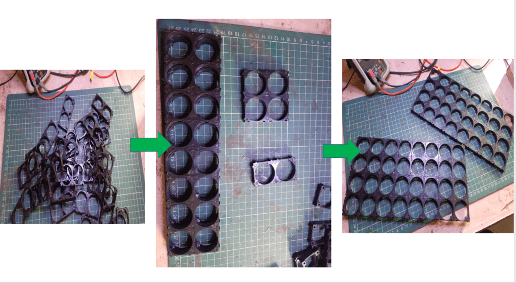
Assembly steps of space holders:
First, arrange the cell holders to make an arrangement of 8 cells in series .you can easily attach them by hand like puzzle chips. by attaching 2 of them side by side. make such 8 pares and attach them together to make a structural configuration of 8*4. We have to make 2 such rectangular shape holders, one will be used at the bottom and another one will be used at the top layer. Use malat for properly fixing them together to make sure not to damage the corner of the cell holders.
Some of the main advantages of using these cell holders are as follow:
1. You can make a custom pack of any size according to your requirement. It’s like solving a puzzle.
2. It provides space between the cells, which allows fresh air to pass and the battery gets cooled easily.
3. It makes your battery pack solid and reliable.
4. It provides safety and anti-vibration to your battery pack.
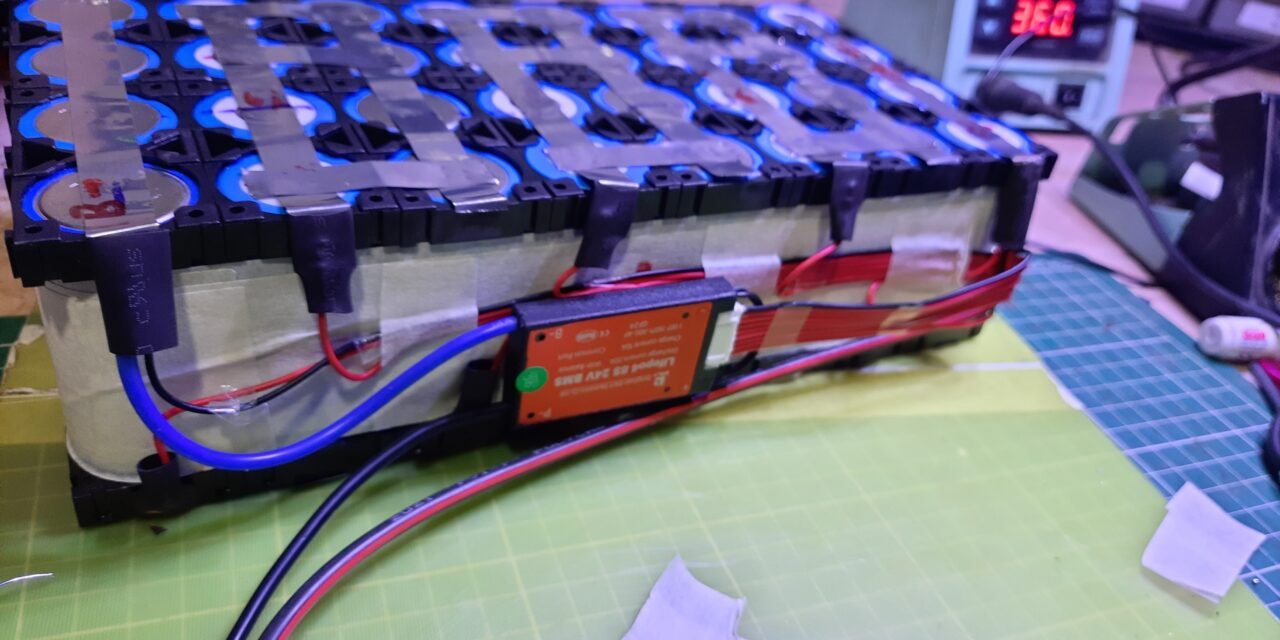
Step 2:Assembling the Cells in the “8S4P” pack:


So to assemble cells in the “8S4P” pack you have to first group 8 cell arrangements in series as done by me in the picture. Where I arrange cells by changing their polarity after each cell. Now you have to arrange the next row of cells arrangement similar to the 1st row considering the polarity in the parallel cell must be the same .now you have to arrange such 4 rows and make the space holder full of cells .while assembling cells use malate to fix them in space holder properly otherwise it will difficult to Spot weld them. Also, note that While arranging in “8S4P” the calculated terminal voltage of the string of cells in series connection must be similar for all 4 Series connections. also, the capacity of each string of 8 parallel connected (each group of 4 parallel cells) must be similar. At last fix the second Space holder structure above the Arranged cell to make a complete assembly.


After assembling every cell. I cut copper paper strips and Stick them in series with each series string to measure terminal voltage. Remember to make sure that the difference between two strings must not be greater than 0.05V.
Step 6:Electrical Designe of “8S4P” pack” :
Warning
From this onwards electrical design of the battery pack starts I am providing a strict warning for those who want to DIY their battery pack. Batteries can be dangerous. Please exercise caution when building your pack. The LiFePO4 cells referenced below can discharge very large amounts of energy quickly, almost like large capacitors. Use caution whenever you handle your pack, triple check your wiring, fuse where possible. You are responsible for your own project. Cross-check the information outlined below as you will own what you decide to implement.


Step 1: Right method to connect cells: Choosing the Right Battery Strips for connecting the cells in series and parallel is an important factor considering electrical design. Using any improper method to connect cells may lead to increase internal resistance and mall functioning of BMS and can cause problems like battery heating issues and less efficiency.
To make the battery pack, you have to connect the LiFePo4 cells together by means of Nickel strips or thick wire. Generally, Nickel strips are widely used for this. In general two types of nickel, strips are available in the market: nickel-plated steel strips and pure nickel strips. I will suggest using pure nickel. It is a little bit costlier than nickel-plated steel, but it has much lower resistance. Low resistance means, less heat generation during the charging and discharging, Which leads to longer useful battery life. Nickel strips come with different dimensions, lengths, and shapes .there are two types of nickel strips available in the market stepwise one is “H” type and another is plane. I personally use plane type with dimensions of 12mm brief and 0.1mm thickness which is capable to conduct a max of 7 Amp. Which is sufficient according to the current rating and electrical requirement.
Step 2: Right method to attach nickel Strip with cell:
You have two options two connect the cells together: 1. Soldering 2. Spot Welding
Soldering :
The best choice is not other than Spot welding .but it is much costly than a good quality of soldering Iron which is available to me in the lab .but the region of not using soldering Iron is that it applies a lot of heat to cells while soldering and it may penetrate throw the cell and it doesn’t dissipate very quickly. This enhances the chemical reaction in the cell which damages the cell’s performance. Ultimately cells will lose some capacity and life of the cells.
But if you are not interested to buy a costly Spot Welder, you can solder the nickel tabs to the cell by following some precautions and tricks :
1. To minimize the contact time of your soldering iron on the cell, make sure the surface is scuffed up sufficiently and you use plenty of flux to allow for fast solder flow.
2. It is better to have a good quality high wattage ( min 80W ) iron with good thermal capacity so it can deliver the heat to the joint quickly so you don’t have to hold the iron to the battery for ages and let the heat seep into it, causing damage to the battery.
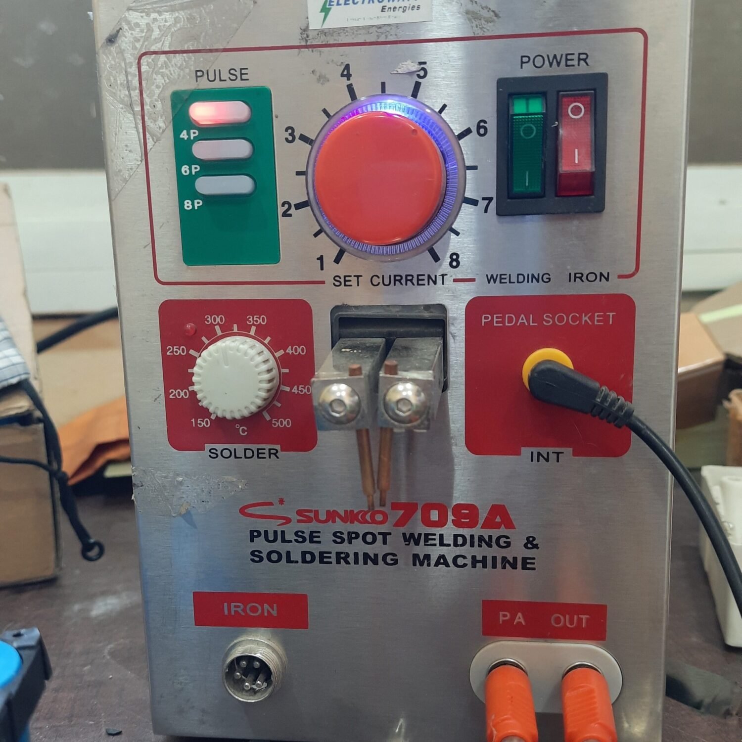
Spot Welding :

The reason goes with spot weld is because it securely joins the cells together without adding much heat to them. As I say we do have not any spot welder available in the lab. I decided to buy one. There are two grades of spot welders currently available in the market: hobby grade and professional grade. A decent hobby-grade Spot welder costs around ₹2000 to ₹2500, whereas a good professional grade may cost around ten times more. So I Order a DIY spot welding Kit from amazon. But it takes a long time to despatch at my place as the manufacture of this machines are manly at china. My second plan was to bring my battery pack assembly to the workshop(ElectroWatts Energy Manufactures of LiFePo4 battery paks) from where I bought all necessary LiFePo4 batteries and material. I also tried to make my own spot welding machine which did not work properly.
So on Saturday 18/09/2021, I went to Pune for welding my battery assembly to Pune at electrowatt workshop. Staps are as follow.


Step 1: Cutting nickel strip of desire shape for connecting cells in parallel and series.
No. of Nickel Strips Required to connect cells in parallel for 8S4P configration=(2 Stripes for connecting 4cells in parallel ) *8=16 nos
therefore I cut 16 long nickel strips for connecting cells in parallel each group of 4 cells. 8 packs of 4cells in parallel connected, each pack required 2 strips to connect cells parallel each other.
No. of Nickel Strips Required to connect cells in Series for 8S4P configration=(3 Stripes for connecting each pack of 4 cells in parallel ) *7=21 nos
and 21 small Strips to connect each group of 4 parallel connected cells in series. To connect each group in the Series. I use 3 stripes. As the max charging and discharging current rating of BMS using is 20Amps and each nickel strip is capable to carry 7Amps .nickel strip used by me. So I assume 3 nickel Strip can carry around 7*3=21Amps. which is more than enuff for me.As the current requirement for my motor is 12 Amp.
Note: make sure to consider the desired values for your configuration of the battery pack and the current rating of nickel stripes you are using to make your battery pack .you can follow the above method .but the figures may not be the same.
Step 2:Spot Weld the Nickel Strips for the parallel connection of the battery pack of configuration “8S4P”:

Top View 
Side View
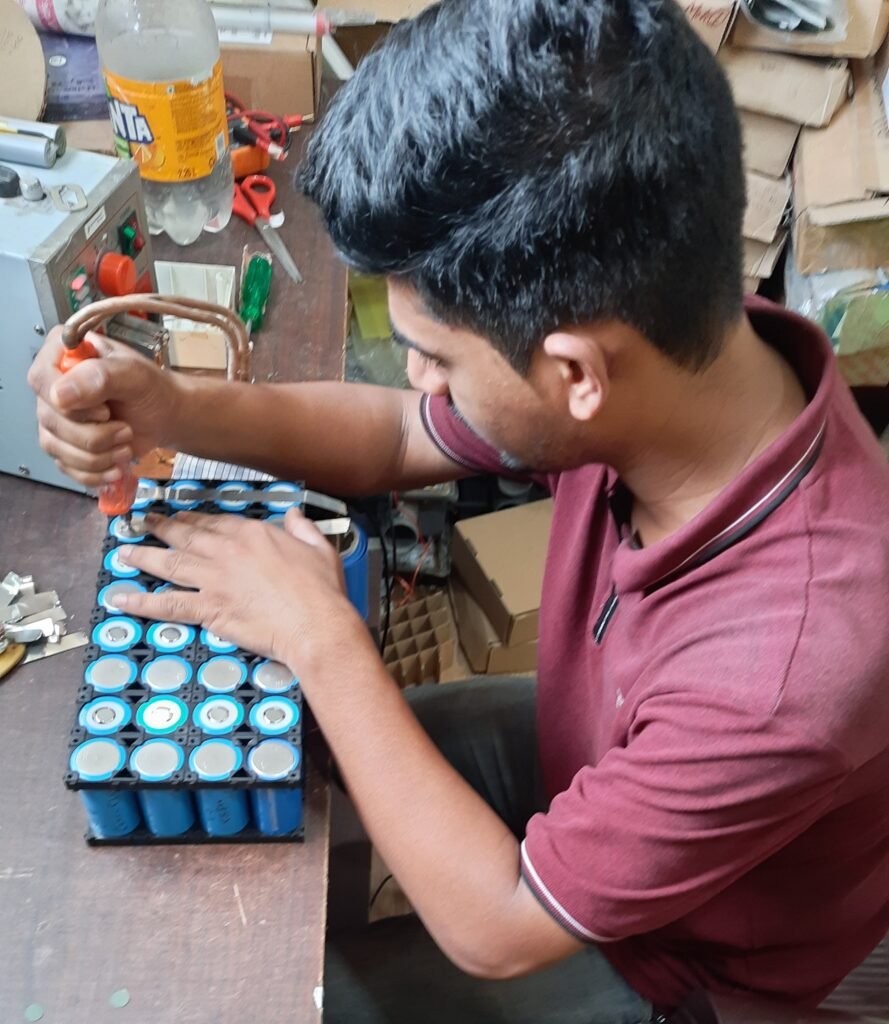
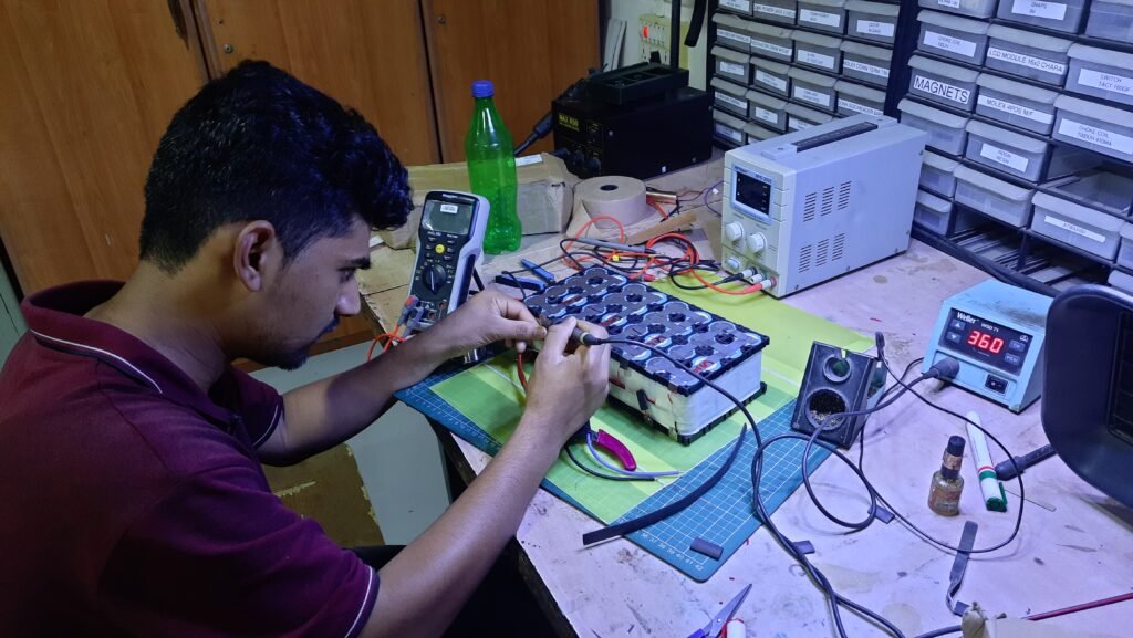
It is recommended that to first spot weld all the parallel connections in the battery pack then move towards the series connections. procedure for using the Spot Welder: here I am talking about the Spot welder that I have used in this project at the Electrowatt energy factory workshop. The Spot welder has three welding choices: fixed welding head, fixed welding head with foot switch, movable spot welding pen with the footswitch. I prefer to use the third option that is a spot welding pen with the footswitch. In this mode, you have to hold the spot welding pen on the nickel strip on the cell cap and press the footswitch for making a spot make sure to repeat this process 2to3 times for welding each cell with the strip. check the weld quality by pulling on the nickel strip. If it doesn’t come off with hand pressure or requires a lot of strength, then it’s a good weld. If you can easily peel it off, then you have to increase the current.
Safety Note: Before starting the spot welding, always wear safety goggles. also do not touch any metal or conducting material to direct contact to open terminals of cells as it leads to a sudden shortage of current and may catch a series of fire issues.
Step 3:Spot Weld the Nickel Strips for series connection of battery pack of configuration “8S4P”:
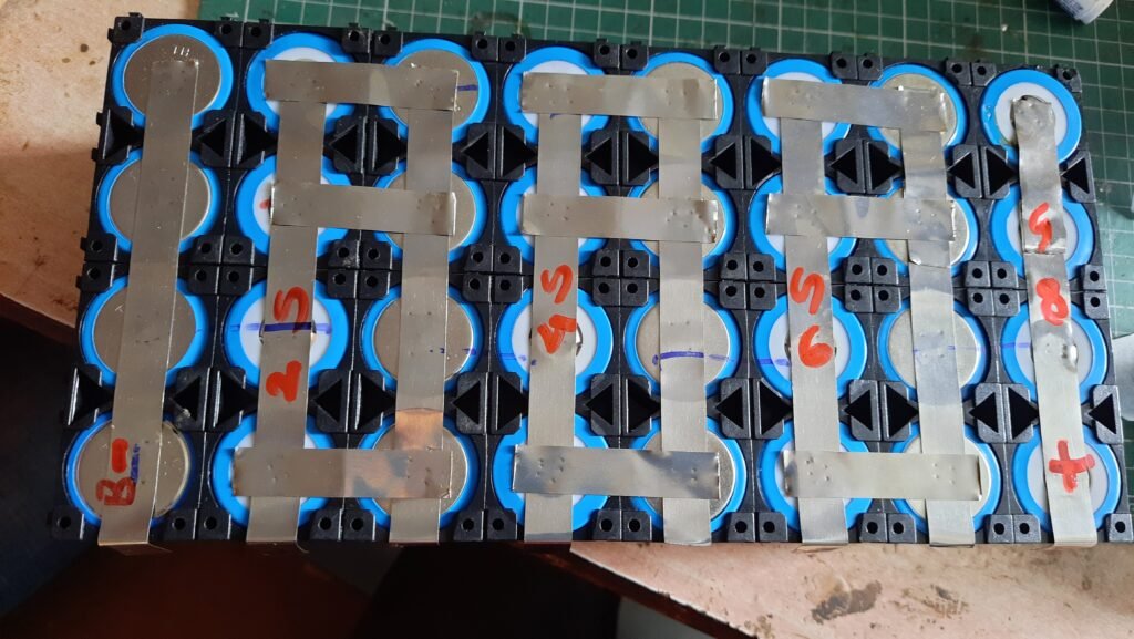
Top View 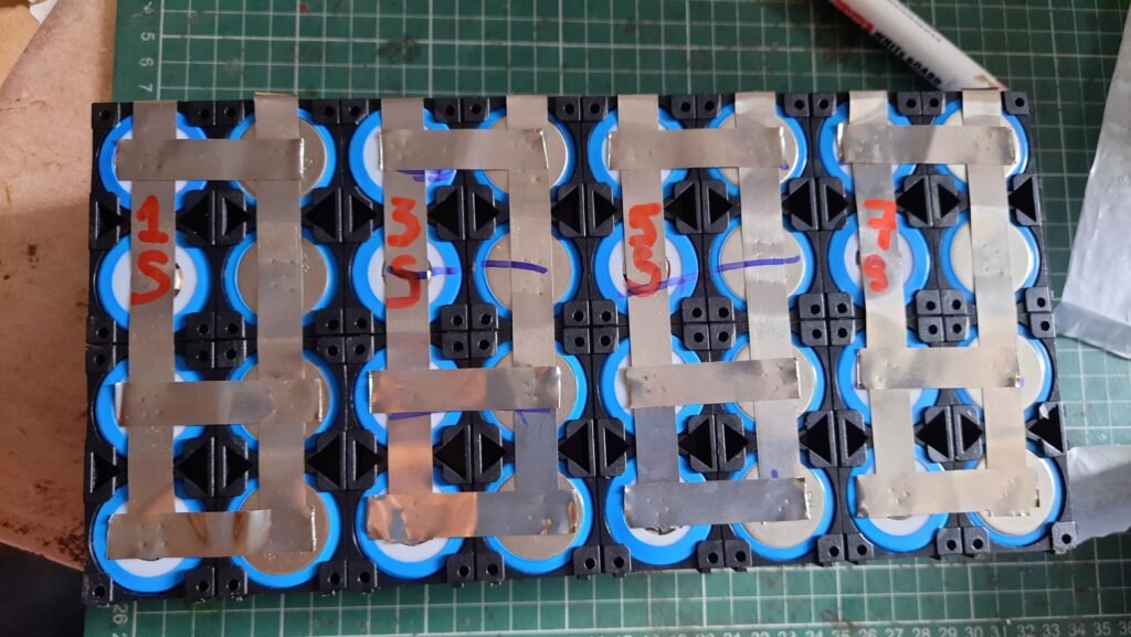
Bottom View
It is recommended that to do parallel connections before series connections as I told before it may close series accident. Make sure to mark all series connections before spot welding using a marker pen and also mark the Vcc and Gnd terminal of the battery. Recheck your connections twice. Keep your battery pack away from any conducting material and make sure not to connect nickel strips accidentally to close the circuit of batteries as it can cause a short circuit. I by mistake mark the wrong connection in the series which lead to a short circuit and burn entire nickel strip and cash fire as you can see in pictures when I just place the nickel strip on it .when happens one of the people in the workshop immediately separate the strip using some non-conductive material (plastic strip ) to brack the circuit. due to this my strip in one of the parallel connections get damaged which I have to cut and spot weld again. So make sure you first make the connections properly as I did.
Step 7:Adding BMS and Arranging the Cables :
What is BMS and why it is used in batteries?
So far we are saying BMS in this blog. But what it is and why it is so important.BMS stands for Battery management system. It performs several functions. . The main functions of BMS are overcharge protection, over-discharge protection, over current protection, short-circuit protection, temperature protection of the Battery. Also, BMS may actively ensure that all the cells that compose the battery are kept at the same voltage or the State of Charge, through balancing.
Selection Of BMS for your battery.
The two important parameters required to Select a BMS are: i) Number of cells in series – like 4S/ 6S /8S
ii). Maximum discharge Current – like 20A /30A /50A. As it clearly seems it depends on the Battery type, its configuration, and Amp you are going to consume.
Always remember that your BMS Discharge Amps must =(Battery Amp-hr)*(normal C rating for discharge per cell) =24A-hr*1C=24A So in my case it must be <24A that’s why I chose 20A discharge BMS.
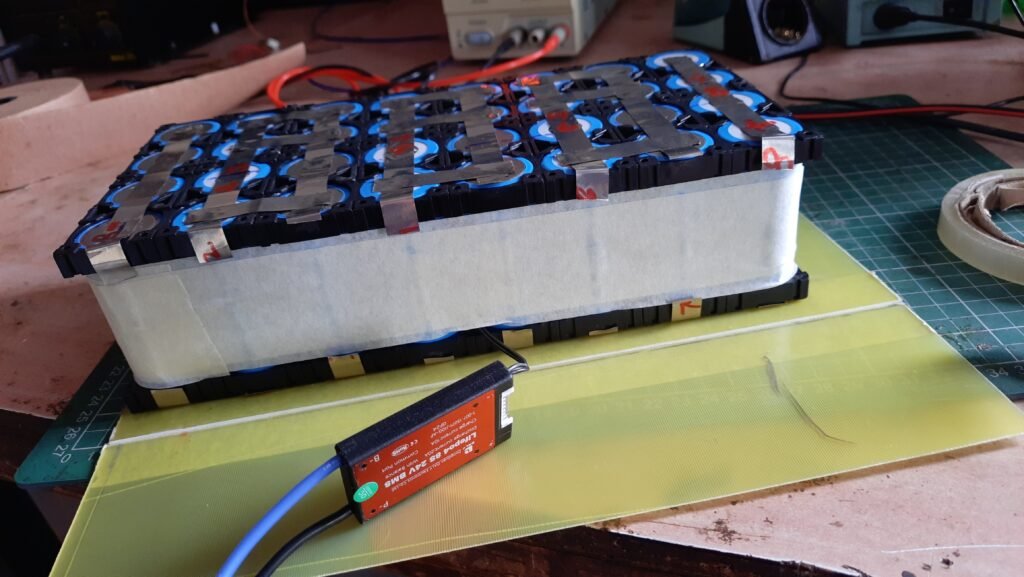
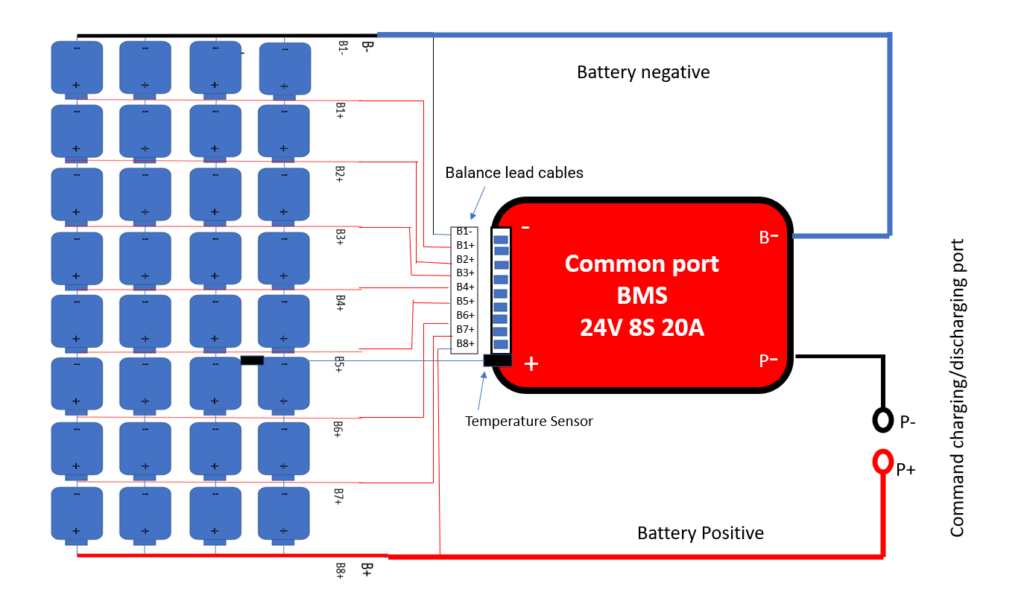
For this project, I have used LIFEPO4 8S 20A BALANCE COMMON PORT BMS 3.2V LIFEPO4 CELL – 24V BATTERY. given in the link.
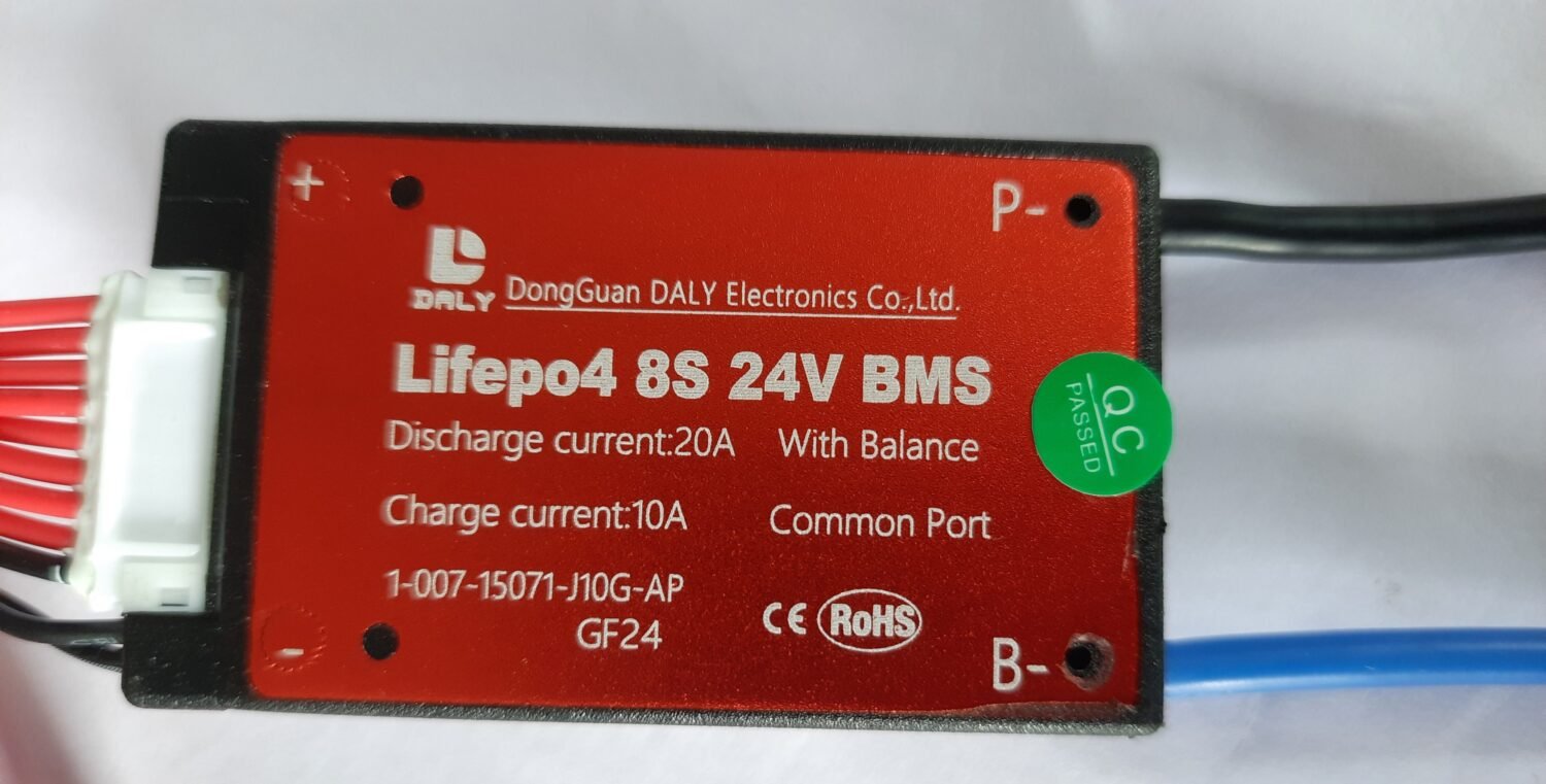
Also, there are two types of BMS available in the market base on their discharging and charging port. Separate port and common port whereas the separate port has another wire for charging because they have a large Current discharging capacity. In the common ports, the charging and discharging ports are the same. with compare to lower discharging capacity and less complexity that’s why I prefer to go with it.
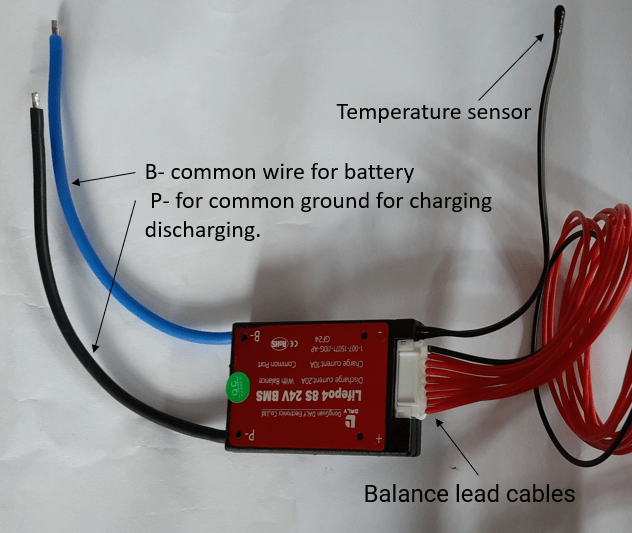
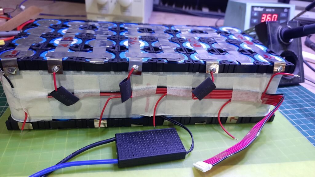
BMS that I am using consists of a thermal sensor,8 cell voltage balancing lead wires, B- common wire for battery, and P- for common ground for charging-discharging.
Here is Scamit from my battery connection of BMS.
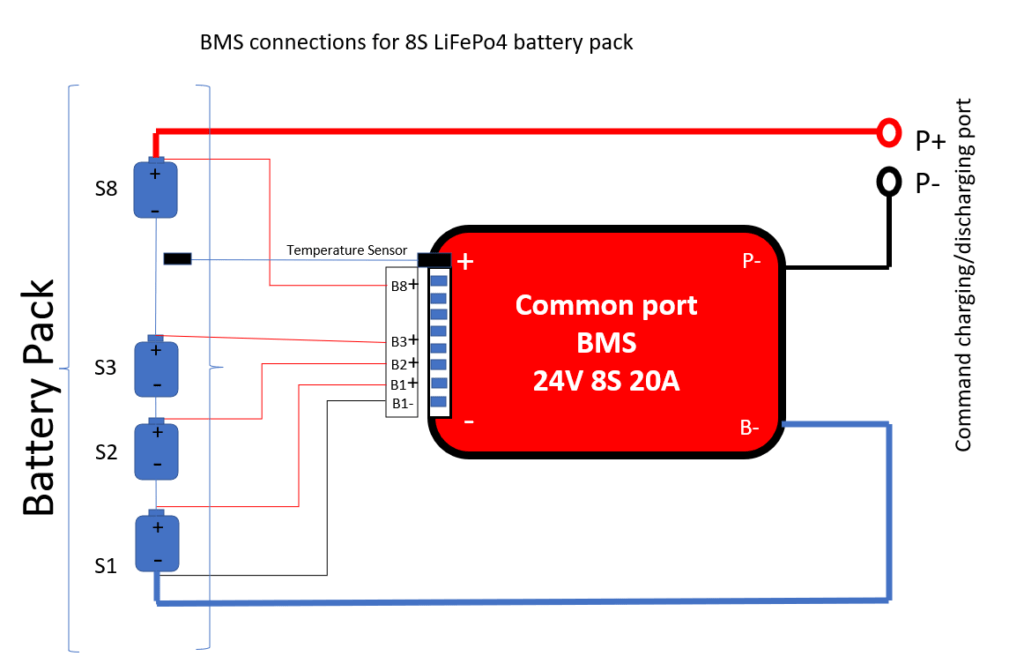
Here are the stapes of how I connect my BMS to my battery pack.
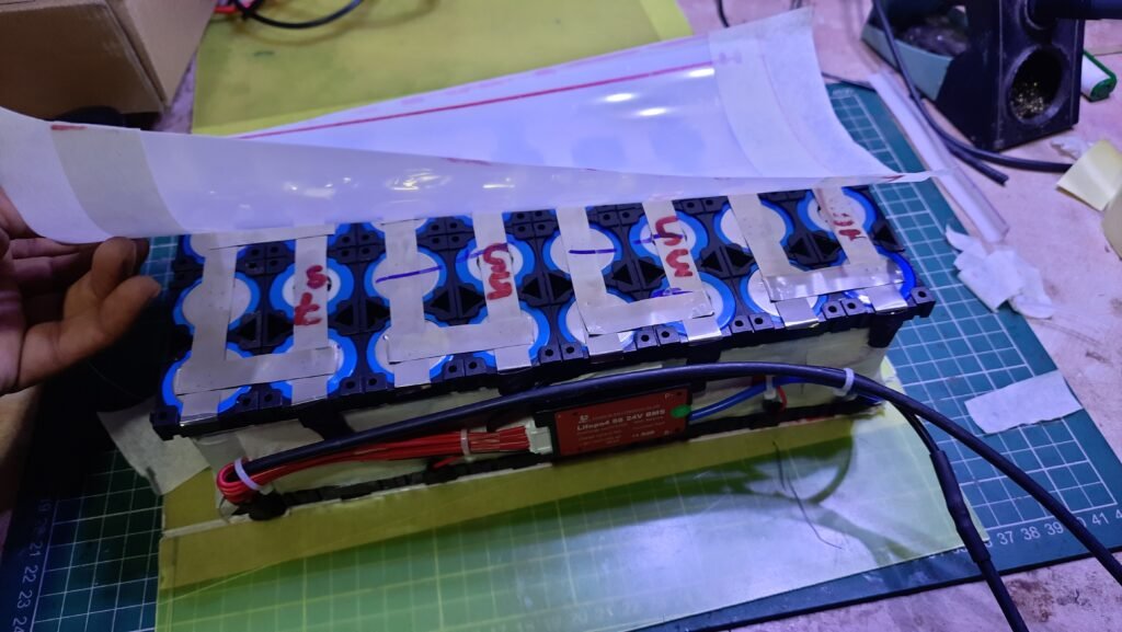
Step1:Attach Temperature sensor In between the cells.
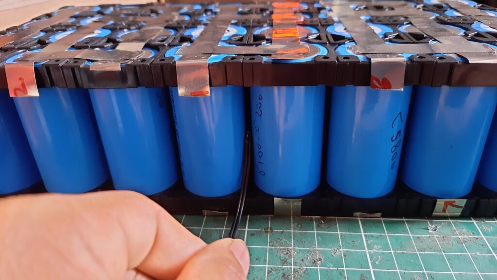

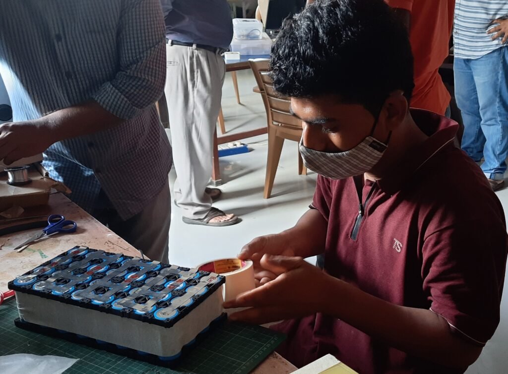
I did it after assembling my battery pack so I have to attach an outer series of cells. But I recement that to attach them in between the battery pack at the model of the cells. As it is going to monitor the temprature of the battery pack. I use paper tape to stick the sensor. But Irecoment that to use Kapton tape instate of paper tape. As it can sustain more temperature and I haven’t one So I go with paper tape.
Step1:Covering the battery pack.
Then I cover the cells using again paper tape(Recommended to use Kapton tape ).To protect cells from outer wiring and all
Step1: Cover the cells pack using paper tape(Recommended to use Kapton tape ).To protect cells from outer wiring, short-circuit, and all.
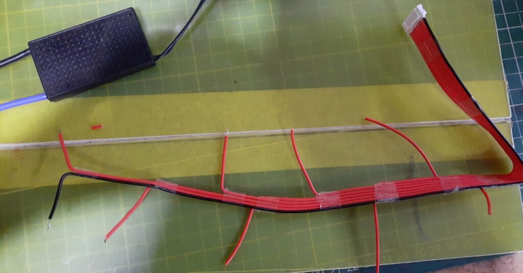
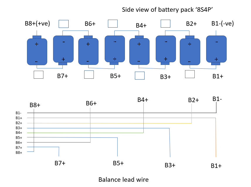
Step2:Making place for BMS and Balance lead cable on the battery pack. Cut the wires in such a way that they can easily get soldered without and wire junk. I cut them into branch-type structures so that I can properly solder them on the respective nickel strips.


Step3:chack all branches of balancing lead cable are in the right location by using a multimeter continuity mode
Step5:After confirming that all balancing leads are in the right position. Solder them on Defined nickel Strips respectively.


Step6:Cover all solder nickel strips using heat shrink tubes. using a hot air gun. It will protect the soldering and stripe.


Step7: Now Solder the main DC wire as Vcc of battery to marked Battery +ve. I use a 4sq.mm, DC solar cable multi-core wire as my +ve. As my battery discharge current rate is 20A it can handle it very easily. I refer universal wire size chart for selecting the size of wire I needed for the battery pack. but I advise using the wire as per your current rate of the battery.
you can refer to the below link for knowing the wire specifications as per your battery current rating.
https://www.altestore.com/diy-solar-resources/wire-sizing-tool-for-12-24-and-48-volt-dc-systems/


Step8: Now it’s time to stick BMS in its place. I use to please BMS on the right side of the battery pack because it felt convenient to make all wiring connections from there. Uses double-sided tape to stick the BMS on the battery pack.

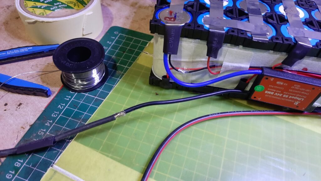
Step9: Now connect the B- of BMS to battery -ve. it is too mashy to connect both wires from balancer lead and BMS main B- to solder together At -VE of battery. Also, I Solder 4 SQ.mm DC wire to P- of BMS To make it long enuff for the battery pack. And not to forgot to cover it using a heat shrink tube.
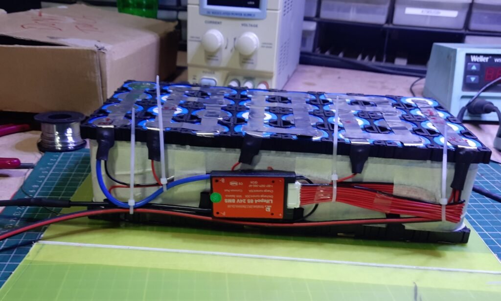

Step10: After all connections and wiring, I tia all wires using cable tia.it makes all bunch of wire together. And finally finishing all this stuff. I chack the end terminal voltages of my final assembly. It was showing me 0.45v .which was a bad sign. I initially thought I short my BMS and got very panicked. I cool down and started to check all the connections again and I found the balance lead wire connections were not fixed properly and after connecting them properly. It started to show voltage.
STEP 8: Insulating & Thermal designe :

Step1: For insulating top and bottom Nickel bus Strips I use PVC paper which is capable to sustain higher temperatures and also works as a grate insulator. If you have a Keaton Tape you can insulate the strip using it. But it is important to insulate electric buses to prevent short circuit and thermal issues.


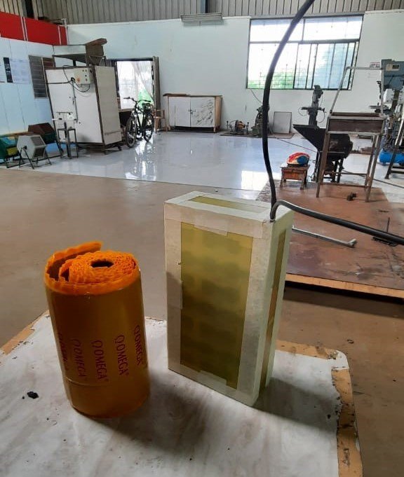
Step2:Now I have to make an enclosed box (for my battery pack. Which have good thermal resistance, mechanical strength and are Easy to fabricate I use FRP (Fiber-Reinforced-Polymer )sheets as a desirable material for making one. I cut them using a mica cutter taking suitable dimensions. use paper tap to stick pieces ensuring that all battery assemblies get perfectly fit in it. Make sure the inner battery pack will not displace due to external vibrations.

Step3: After enclosing the battery pack in the FRP box. Then I try to fit it in my cycle carrier and was surprised it was perfectly fit in it. As we decided to make the battery fit and nonremovable to make it less complex.


Step4: One of my friends in workshop Ghansham who has great knowledge in automobile hands-on work .ask me about the waterproofing of battery packs. As it is surely in future that the battery pack comes in contact with water. So he suggests I seal the battery using a compound rubber sheet which will make it waterproof. He helps me to make it possible.


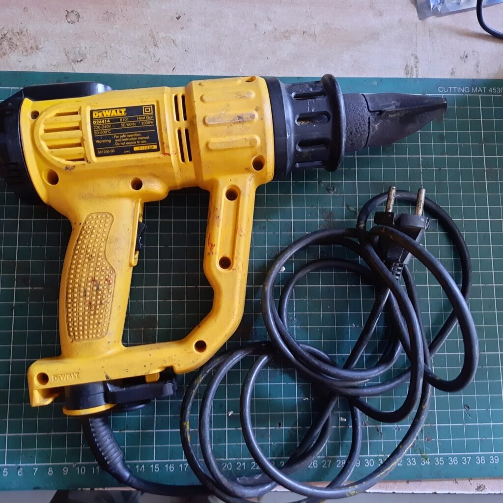
Step5: This is the final stage of making a DIY LIfePo4 battery pack .where we seal the outermost layer of the battery using a PVC tub as most of the battery packs have an outer cover. we see the heat gun setting temperature around 350*C to make it shrink.be careful full and don’t keep the hot blow at one place as it gets tear-off due to excessing.I and Ghanshyam try our best still we make a cut on it.


