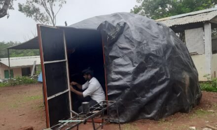
To review the earlier work on plastic belling machine, please refer the following blog.
http://vadic.vigyanashram.blog/belling-machine/
Objectives :
To design a mechanism which will compress the waste plastic (end use polythene bags) , reducing the volume & increasing the density so that it can be easily loaded in pyrolysis unit and also can be easily transported in van in bulk quantity. Aim of compression is 1 : 3.
Calculations for Design of metallic Gears :
28 Aug 2021 – 4 Sept 2021

Terminology of Spur Gear :

Module :
Module defines tooth size of the gear.
If two gears are in contact module of both the gears should be same.
formula , module = Pitch circle diameter / number of teeth
Gear ratio :
i = np / ng = zg / zp
Pressure angle (alpha) :
It is the angle between the resultant force and the common tangent at pitch point.
- if alpha is less power transmission is more but the strength reduces and noise increases.
- because width at bottom of tooth reduced.
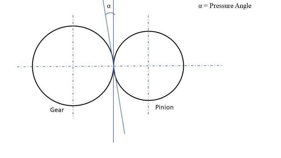
Standard values of pressure angle are 14.5 degree and 20 degree.
Minimum Number of teeth to avoid interference is given by (For pinion)
Z min = 2 / sin2 (alpha)

Force Analysis :

tangential force (PT ) :
PT * (d/2) = Mt (Torque)
PT = 2 Mt / d
Normal force(PN ) :
PN = PT tan(alpha)
Stress Calculations :
Beam Strength :
- maximum value of PT , the tooth of gear can sustain without failure.
Bending Stress :
Assumptions :
- There is only one pair of teeth in contact
- Direct compressive stress due to PN is negeligble
- PT is uniformly distributed over the entire width
- PT is static
Bending Stress in teeth (Sigmab) :


Maximum Pressure applied :
9 Sept 2021
Uptill now we don’t have any figures of how much pressure we are applying to compress the plastic. In technical review with Dr.Arun Dixit and Engineering team we have decided to calculate that pressure.
To Calculate the maximum pressure we are applying to compress the plastic we have done one experiment.
Firstly we have holded the gears at a certain point and then gradually started to load the machine.
At a certain load we observed that if we keep adding more load in it the teeths of the gear will break so we have stop adding load and taken the weight of that load.
Calculations –
Load = 4.2 kg
Force = 4.2 kg + 0.3 kg (weight of plunger and assembly) = 4.5 kg
Pressure = Force / area
= 4.5 / (20 *20 cm )
Applied pressure = 0.01125 kg/cm2
Change of Mechanism :
12 Sept 2021
We observed that the pressure we are applying to compress plastic is very small and insted of designing a gear box we can also use the lifting mechanism which are available in the market.
So, we have decided to move on car jack available in the market.
Car Jack and Bellow Market Survey :
13 Sept 2021 – 15 Sept 2021
Now we are zero down on the car jack mechanism.So, I have done a market survey to konw types of car jack available in the market, their lifting capacity and cost.
And form the conclusion of the trials of present prototype their is small water leakage form the bottom side( hole of the shaft). So, my another task is to find bellow as per our requirements to seal that leakage. I collected the contacts of different vendors who makes custmize bellows from INDIAMART and discussed with them requirement of bellow and cost.
Dimensions of Block Size :
16 Sept 2021 – 20 Sept 2021
We didn’t have any figures of which block size we are going to make form the baling machine. The block size were decided with the help of ‘Pyrolysis Unit’ we decided to make a block of size from which we can fill the Heating tank of Pyrolysis unit at maximum volume.

- The diameter of inlet is 220 mm
- Heating Tank Dimensions – Inner Diameter = 330 mm , Lenght = 1280 mm
- Volume of tank = Pi*r*r*h = 100000 cm3
Constraints to define the block size
– Heght or width of block should be less than 155 mm
We have taken many iterations to decide a proper block size.
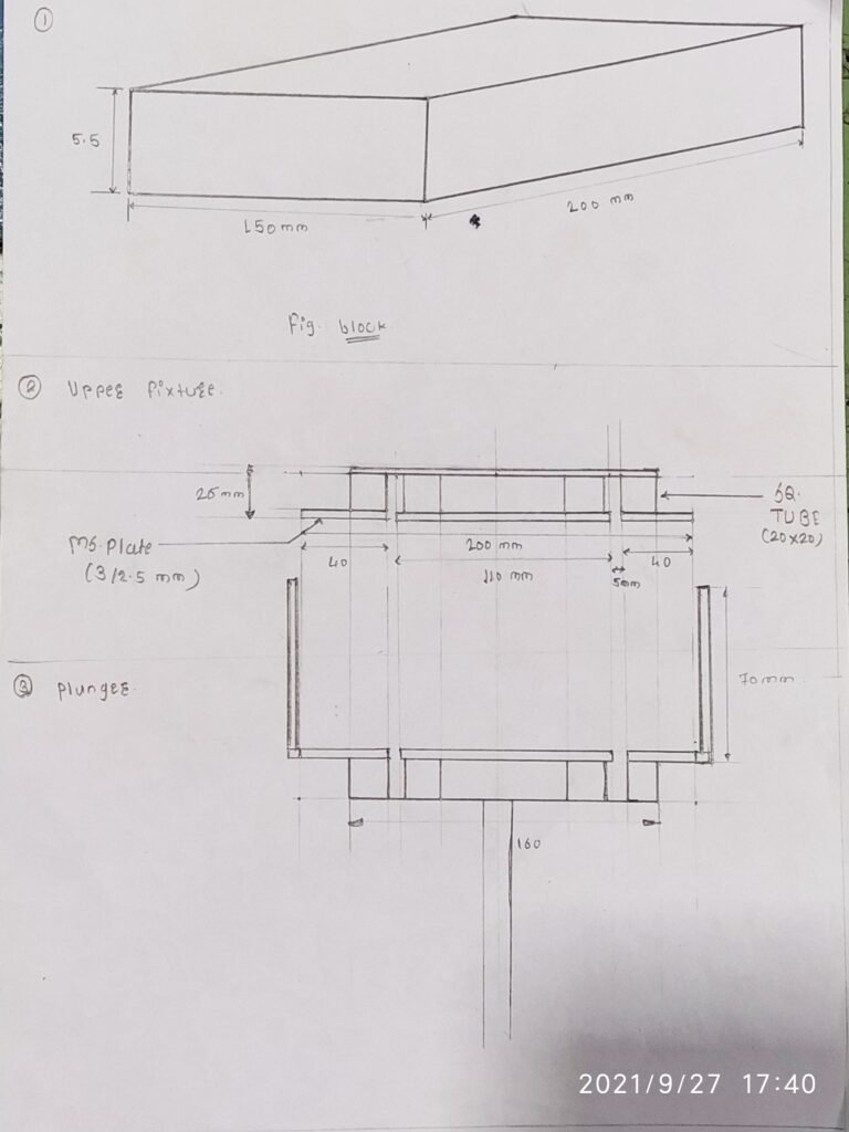
and decided to make a block of size 150mm * 200mm * 55 mm(lbh)

We can insert approximately 42 blocks of size 150mm * 200mm * 55 mm .
The volume of 42 blocks = 69300 cm3
so with this dimensions we can fill the tank upto 69 %
Rough Hand Sketches For new design :
21 Sep 2021 – 23 Sep 2021


Upper Fixture and Plunger 
Container Front view 
Container Side view 
Plunger top dead position 
Hydraulic Jack 
Structure
SolidWorks Design :
25 Sep 2021 – 27 Sep 2021

Front View of Container 
Side View of container 
Isometric View

Upper FIxture 
Upper Fixture Supportive plate 
Container Flange

Upper Fixture Assembly 
Plunger 
Connecting Rod

Structure FV 
Structure SV 
Isometric View

Final Assembly 
Final Assembly
Bill of Material :
28 Sep 2021
Fabrication
4 Oct 2021
Plasma Cutting :
- CAD files are saved as .DXF format
- Then DXF files opened in FASTCAM software
- and converted to machine code and open in plasma cutter
- Drafted Drawings :

Plasma Cutting 


Container After Bending and Welding 
Solution for the Leakage :
To stop water leakage from bottom hole of shaft I have used cycle tube as a bellow one side is fixed to the bottom plate with the help of flange coupling and another side is fixed with the hose clip to the rod.
Prototype
18 oct 2021
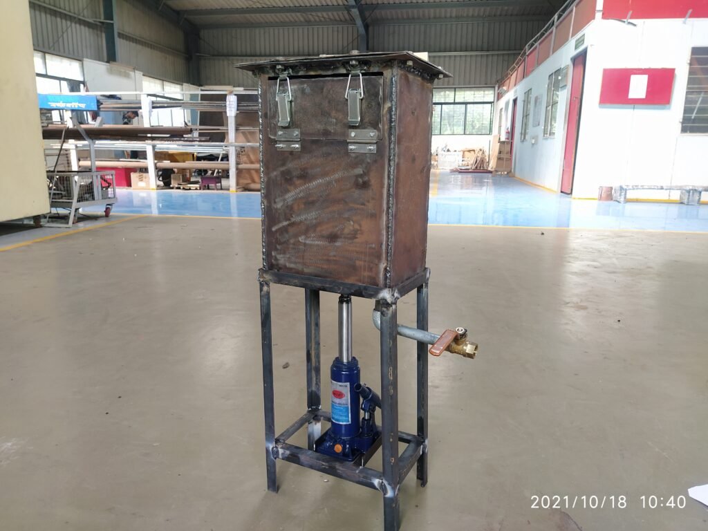
Fabrication is completed and now our baling machine is ready to test…..


Hydraulic jack Mechanism 
BDC of Plunger 
TDC of Plunger
About the System

- Total Height = 830 mm
- Weight = 17.4 kg
- Volume of Container (LBH) = 260 mm * 170 mm *380 mm = 16796 cm3
- Available Volume = 220 mm * 170 mm * 195 mm = 7106 cm3
- Volume below the door = 260 mm * 170 mm *260 mm = 11492 cm3 = 11.4 ltr
- Hydraulic Bottle Jack used.
- Capacity 5 Ton
- Height of Jack 190 mm
- Piston travel 125 mm
- Plastic capacity upto 1200 gm
Trial Report
PDF of trial details :
1st Trial :
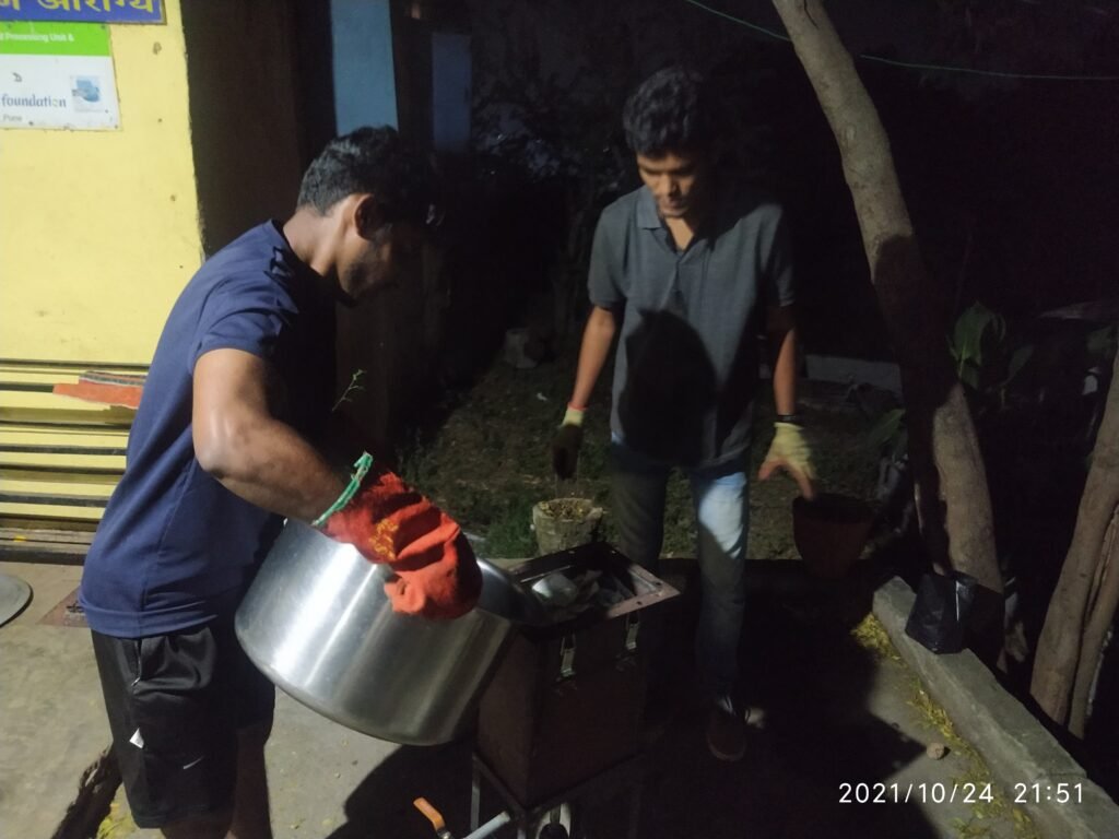
24 Oct 2021
Cold press :
Trial 2 :
24 Oct 2021
Hot press


Comparision 
Discussion With Dr. Arun Dixit sir after the 1st hot water trial:
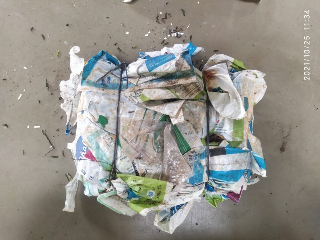
The compression we got in 1st cold press trial is 1 : 2.5 and 400 gm plastic was inserted and in 1st hot press trial the compression we got is 1 : 1.33 and 650 gm plastic was inserted.
Press type
Initial Volume
Plastic Weight
Volume After press
Cold Press
21 * 17 *20 cm
400 gm
21 *17 *6 cm
2142 cm3
Hot Press
21 * 17 *20
650 gm
21 *17 *8 cm
2856 cm3
Therefore , 2856/2142 = 1.33
x = ( 2856 * 650 ) / 400 = 4641 cm3
4641 / 2856 = 1.625
We got 1.625 times greater compression in hot press than cold press.
Pressure calculations :
In this session we have also discussed about the pressure applied to compress the plastic.
I have not fixed the container with the lower fixture so because of that its easy to calculate the pressure with the help of weight of upper assembly.
Weight of upper assemble ( container and upper fixture ) = 11 kg
Water = 11 liter = 12 kg
weight of plastic = 650 gm = 0.65 kg
Weight on machine = 60 kg
Area of plunger = 21 * 15 cm
Pressure = force / area = 83.65 / (21*15)
Applied pressure = 0.2020 kg/cm2
Trial 3 :
Trial 4 :
Conclusion :
- We have got the desired compression ratio.
- The pressure applied to compress the plastic is too low we can apply more pressure on it and get more compression.
- In this system cycle tube is used as a bellow to stop the water leakages but the material is not suitable to expand and conpress with the plunger it requires more force to compress.


