Pyrolysis based sanitary napkins incinerator Version 3.1
Background :
Disposal of used sanitary pad & similar kind of medical waste has been a very common problem. In general the used napkins are thrown to dustbins or flush in to t he drain. The open disposal of soiled pads not recommended due to hygiene issues. Disposal problem is difficult due to use of gel forming polymers used in modern day’s pads. It has also a taboo factor attached to further increasing complicity of disposal. Incineration of medical waste is one of the possible ways to dispose sanitary pads.
Incineration Process –
Incineration is a thermal waste treatment process that involves the combustion of organic substances contained in waste materials. Incineration of waste materials converts the waste into ash, flue gas and heat.
Problems with Direct Incineration –
The pads are wet during disposal, so during incineration the amount of smoke observed from exhaust/ chimney is too much and the flue gases generated are pollutants. So direct incineration of soiled pads is not a good waste disposal method.
To solve this problem we use pyrolysis process for soiled pad disposal;
Pyrolysis Process –
Pyrolysis is the thermal decomposition of materials at elevated temperatures in an inert atmosphere. The products of pyrolysis are combustible gases. So, by complete combustion of those gases the problem in direct incineration can solve.
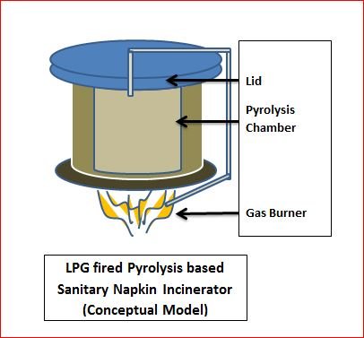
On the principle of pyrolysis Incinerator is deigned and developed in Vigyan Ashram.
Existing Version –
An incineration device has been developed that uses pyrolysis to decompose sanitary napkins into hydrocarbon vapours and combustible gases along with some non-combustible gases and char. These vapours and gases are made to pass over high temperature electric coils (>5000C) where they auto-ignite in the presence of oxygen. The heat from the flames partially drives the pyrolysis of remaining sanitary pads. Combustion conditions that result in a transparent flue gas exiting from the chimney.
Limitations with Existing Version –
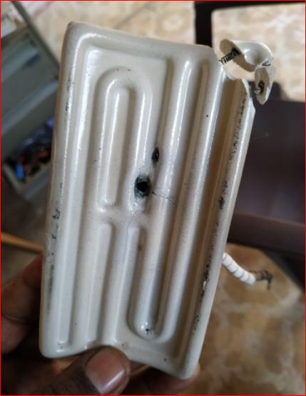
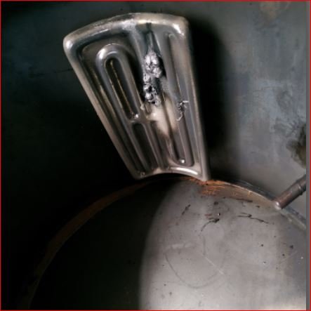
- Electrical heating coil is given at below the pyrolysis chamber which is used to burn the gases from pyrolysis, and the heat generated is utilized to heat the pyrolysis chamber. During this process the heating coil get fused due to uncontrolled temperature.
- Uneven heating of pyrolysis chamber due to improper location of the heating coil.
Proposed Design –
This system will be based on drying & pyrolysis process to decompose sanitary napkins into combustible gases and char. This system will firstly prefer for drying of sanitary pad at 1000C-1200C temperature. Then pyrolysis process will happen to decompose dried sanitary napkins at 4500C-5000C temperature, hence generates combustible gases & char. These generated combustible gases also utilize for heating reactor through burner. But initial heating would be done by the electrical heaters. In this system we also go for directly pyrolysis to decompose waste plastic into combustible gases & char.
Design Process
1. Ideation –
In brain storming with DIC Fellows and Dr. Arun Dixit following considerations were finalized –
- Capacity of the Incinerator – 1 to 20 pads
- Weight of dry pad – 7 to 10 gm.
- Weight of wet pad – 90 % to 93 % of weight of dry pad.
- Basic Dimensions
- Operating Temperature Range
- Heaters
- Chimney and exhaust system
- Air Supply for Drying phase
- Apparatus Cleaning and Handling
By considering the above points 1st 3D model done as following ;
Model A
Model A: 1st 3D CAD Model (Full View of pyrolysis chamber)
Model A: Section View
- Model A is with SS container (220mm height 180mm dia. And asbestos as a gasket material which is used in IC engines. The upper lead and incinerator male reactor will get attached with each other by nut and bolt arrangement similar to autoclave.
- Model A has ceramic heaters on bottom 1/3rd area of periphery with air blowing in order to push out vapours generated. First drying phase will operate in 110130 degrees.
- The real incineration will happen below pyrolysis chamber same as V1 pyrolysis model (subir sir).
Model B
following points raised in further discussions;
- How much heat will generate by incineration of pyrolysis gases. The weight of polymer is close to 140 grams or 20*7 grams. We guessed the heat generation equivalent to incineration of 140 gm of cotton. This heat is negligible not very substantial hence we decided a trap between heat utilization and ease of manufacturing. The second model be hence proposed with incineration of paralytic gases at the end of chimney.
- Will there be a channelization of air and will air flow accelerate or disaccelerate drying. Knowing the structure of substrate chalking was 100% assure which will result in losses of heat without assisting real dry. Hence it was decided to remove the air blower and suction in model B.
With above considerations 3D modls made as following;
Cross Sectional View of Model B
The following topics also raised during discussions and brainstorming with Mr. Dasnurakar ;
- Possible channelization of hot air.
- Knowing the real life practice and random shape and density of soil pad it was thought that channelization of hot air is almost certain. This will result into loss of hot air without effecting drying.
- On the other hand slow heating through insulated material will lead to less consumption of electricity it was hence decided to remove fan to generate air current. As a result new model proposed it got simplified the next point discuss was incineration of pyrolytic gases.
- . If we incinerate pyloric gases beneath the pyrolysis chamber we will be able to use heat generated.
The cal. To get the saving of electricity by burning of pyrolytic gases is as follows:
- We assume that the calorific value of sanitary napkin pad is equivalent to cotton which in reality will be slit lower. 8gms of cotton per pad will generate 12.8 kcal assuming 1600kcal/kg as calculated value of pure cotton. 2kw heater can generate same amount of energy in 26.7sec. Lead into next consumption of 0.14*10-3 units. Which is equivalent to 1.5paise assuming the unit rate to be 10rupees. That means 75paise saving per batch of 50 pads.
- This was thought to be too low advantage for the capital cost investment. This gave us clear answer that we can incinerate the pyrolytic gas at top of chimney.
2. Material Selection (MOC) –
Following are the options of the materials for the pyrolysis chamber;
- Ceramic
- SS 316L
- MS (CRCA) sheet

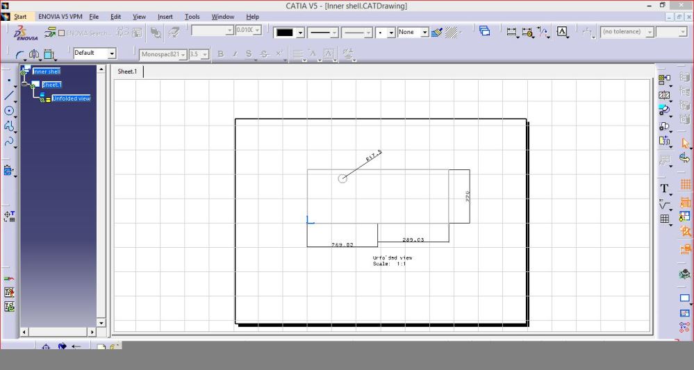
- Inside Chamber Dimensions are,
Inner Diameter – 18.2 cm
Height – 21.7 cm
Perimeter is 58 cm
So it requires 58.0*21.7 cm sheet
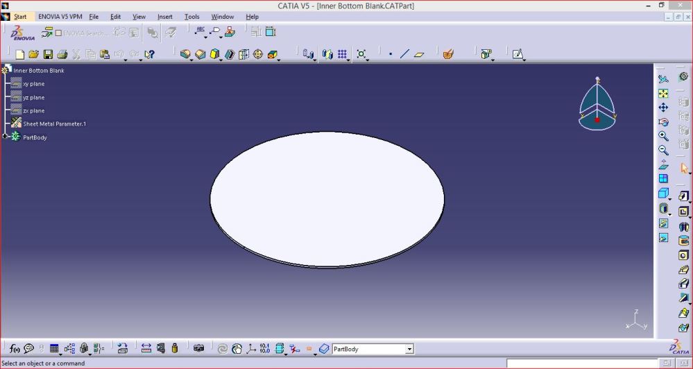
For bottom blank 18.6 cm dia. Sheet For top flange Inner Dia. 18.2 cm , Outer Dia. 31.4 cm
Total sheet required = 4*1 ft.
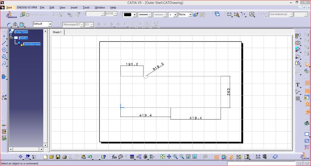
- Outer Shell
Inner Diameter – 26.5 cm
Height – 26.3 cm
Perimeter – 83.8 cm
So, Sheet Size will be 83.8 * 26.3 cm
For bottom Blank 27 cm dia. Sheet
For top flange Inner Dia. 26.5 cm, Outer Dia. 29 cm
Total Sheet required = 5 * 1 ft. - Lid
2 Plates of dia.31.4
Sheet Required = 2*1 ft
# By considering above dimensions Sheet of around 12 sq. ft. is required.
# Thickness of material is 2 mm.
Considering various factors related to heat transfer and thermal cycles during operation of incinerator SS 316 sheet was considered as material of incinerator.
By checking availability and costing of SS 316 it was decided to use MS CRCA sheet of 2 mm thickness for the prototype.
3. Detailed Drawings and CAD Models –
As shown in above conceptual CAD model the assembly is made of three main systems, which ar;
- Inside Chamber (Pyrolysis Chamber)
- Outer Shell
- Lid and chimney
- Inside (Pyrolysis) Chamber
This is the main chamber which will be the air tight vessel with the requirement of avoiding air coming into the chamber which will led to disturbance in pyrolysis process.
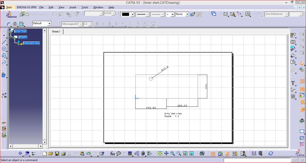
- Inner Shell
It is cylindrical part made of MS CRCA 2mm thick sheet.
2. Inner Shell Bottom Blank
This part is the bottom for enclosing the inner shell and make it air tight from bottom side.
3. Inner Shell Flange –
This flange has to weld with the cylindrical inner shell and will be covered by gasket from top to make air tight joint between lid surface and inner shell. It has also provision of holders to tight the lid using wing nuts.


4. Wing Nut Mount –
This mount will weld to the inner shell top flange to hold the wing nut.

- Outer Chamber –
- Outer Shell –
This is MS CRCA 2 mm thickness sheet rolled vessel for holding the complete assembly of inner shell by making gap between both and filled with glass wool to prevent heat transfer to outside surface.

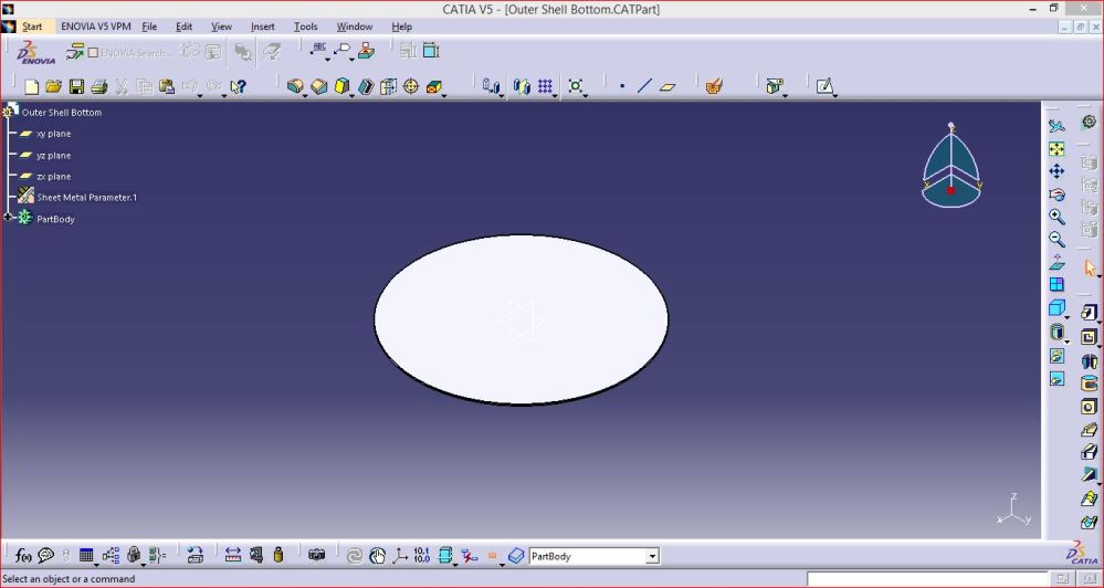
2. Outer Shell Bottom Blank –
This is for enclosing the outer shell from bottom side.

3. Outer Chamber Complete Assembly –

- Lid –
Lid will hold complete pressure building inside the pyrolysis chamber. This will made up of two flat plates joined by round plate and by maintaining gap between the plates filled with glass wool. Also provided handle for handling and wing nut fitting gaps required during locking of the vessel.
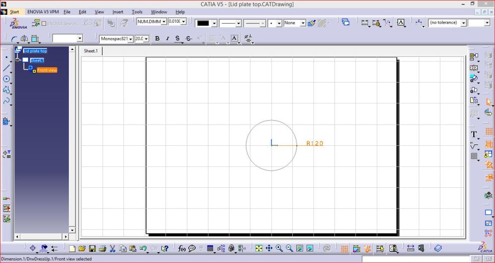
- Lid Round Plate –

2. Lid Top Plate –

3. Lid Wing Nut Mount –

4. Lid Assembly –

- Incinerator Complete Assembly –
Following is the complete CAD assembly of the pyrolysis based sanitary napkin incinerator. It is showing inside pyrolysis chamber, lid and outside chamber.

Fabrication
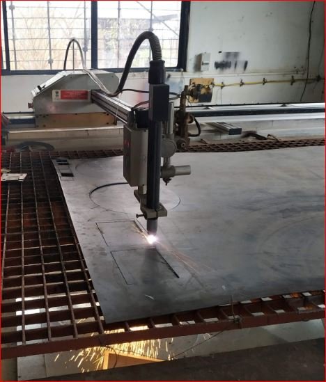
- CRCA Sheet LASER Cutting –
The MS CRCA Sheets cutting using LASER cutting according to the design and .DXF files of the same. The material cutting work outsource from Ms. Kakade LASER Pune, since the CNC plasma cutting machine in Vigyan Ashram is under maintenance.


- Sheet Rolling –
For making inner pyrolysis chamber and outer chamber cylinderical, rolling machine used and rolling done.
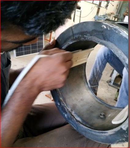
- Welding –
Welding of the joints after rolling done. Chimney pipe also welded to the inner chamber. Flanges at the top of the inner chamber welded and the chamber is tested for leakage checking by filling water. The chmber is found leakproof.Outer Chamber also Welded after checking the sizes of heaters. Heater Mountings welded to the outer surface of inner chamber. Lid is fabricated by welding the wing nut mountings and handle. Insulation of Glass wool between two chambers is filled. Gasket is installed on top flange.

The chamber is tested for its leak proof welding by filling water inside and kept for 3 hours. No leakage observed during the test.
- Thermocouple Mounting –
The J-Type Thermocouple is mounted at the bottom Side to sense the temperature inside the chambermand also at the outer surface of inner chamber to sense the inner chamber surface temperature;

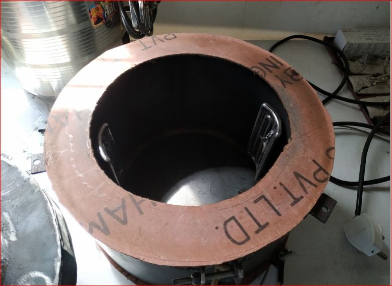
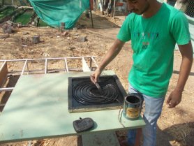
- Heaters Mounting –
Heater details:
Heater type – Ceramic IR heaters (Curved type)
Specifications – 122mm*60mm*500 Watt * 240 Volts AC
Heaters are mounted on the 1/3 rd surface considering vertical height of the pyrolysis chamber outer surface.

This heaters mounted using clamp made from MS CRCA 1.5 mm thick sheet. The clamp having u type notches to hold the heaters outer mounting part. The gap between two heaters is filled by glass wool.

The front side surface of the IR ceramic heaters is in direct contact with the outside surface of pyrolysis chamber.

For mounting thermocouple sealant used to seal the minor gap which can be sustain up to 1000 degree Celsius.
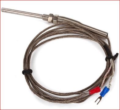
- Thermocouple – J type industrial
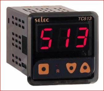
- Temperature Controller – Selec PTC 513
- Thermocouple and LCD display for Inner Chamber surface temperature –

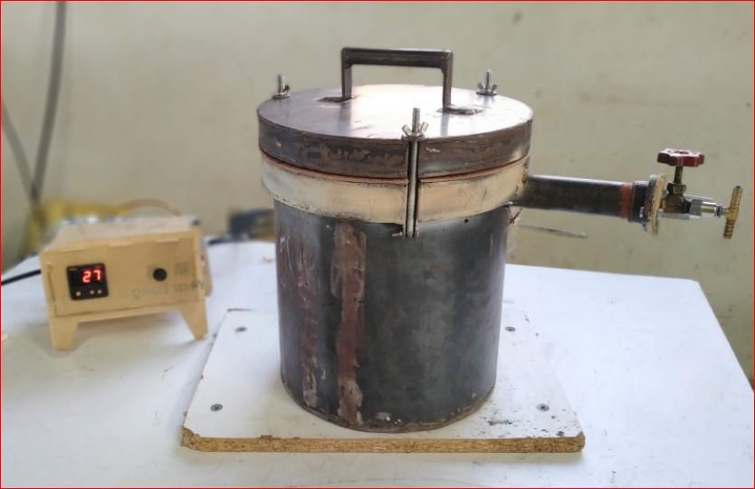
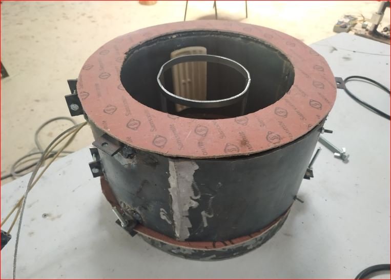
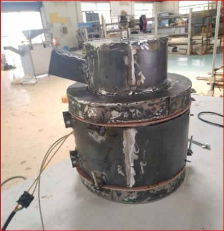
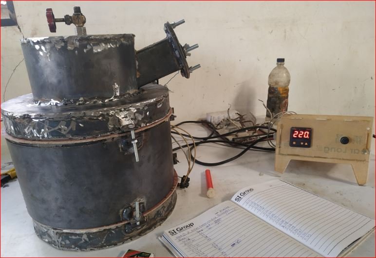
- Final Assembly –
The final assembly of incinerator is demonstrated in following image. Chimney is attached permanently with leak proof welding to the pyrolysis chamber for carrying the combustible pyrolysis gases out for burning.
By considering calculations of calorific value we can get from the combustion of pyrolysis gases done which we found 10 % that of we required for pyrolysis chamber heating if we burn it beneath the pyrolysis chamber, along with this considering design complications it was finalized to burn the pyrolysis gases at the tail of chimney.
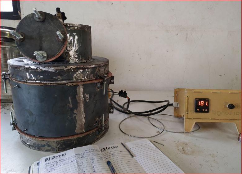
Trials
Trials initiated for testing various parameters.
Idle trial of incinerator taken to understand temperature difference between outer surface or pyrolysis chamber wall and cnter point of the pyrolysis chamber.
Average difference of temperature throughout the trial observed in the range of 200° C to 250° C.
- Trial 1 – Trial on wet cotton
Following are the observations from the trial taken on wet cotton. To make the cotton wet water is added and trial taken.
| Trial 1 Date – 30/11/2018 Trial on Wet Cotton | Total heaters run time = 10 min. 30 sec. | All next 6 trials heaters run time 229 min. = 3 hrs. 49 min. | |||||
| Inside Temperature (Degree Celsius) | Surface Temperature | Time | Time (Minutes) | Set Temperature | Heaters Status | Heaters Run time | Comment |
| 28 | 54 | 16:45 | 0 | 90 | On | Drying Started | |
| 29 | 81 | 16:46 | 1 | 90 | On | Drying | |
| 30 | 88 | 16:46 | 1 | 90 | On | Drying | |
| 31 | 101 | 16.47 | 2 | 90 | On | Drying | |
| 32 | 114 | 16:47 | 2 | 90 | On | Drying | |
| 33 | 127 | 16:47 | 2 | 90 | On | Drying | |
| 34 | 138 | 16:47 | 2 | 90 | On | Drying | |
| 35 | 148 | 16:47 | 2 | 90 | On | Drying | |
| 36 | 159 | 16:47 | 2 | 90 | On | Drying | |
| 37 | 166 | 16:47 | 2 | 90 | On | Drying | |
| 38 | 178 | 16:48 | 3 | 90 | On | Drying | |
| 39 | 187 | 16:48 | 3 | 90 | On | Drying | |
| 40 | 191 | 16:48 | 3 | 90 | On | Drying | |
| 41 | 198 | 16:48 | 3 | 90 | On | Drying | |
| 42 | 207 | 16:48 | 3 | 90 | On | Drying | |
| 43 | 215 | 16:48 | 3 | 90 | On | Drying | |
| 44 | 222 | 16:48 | 3 | 90 | On | Drying | |
| 46 | 233 | 16:48 | 3 | 90 | On | Drying | |
| 48 | 242 | 16:48 | 3 | 90 | On | Drying | |
| 49 | 253 | 16:48 | 3 | 90 | On | Drying | |
| 50 | 263 | 16:48 | 3 | 90 | On | Drying | |
| 53 | 274 | 16:48 | 3 | 90 | On | Drying | |
| 55 | 284 | 16:49 | 4 | 90 | On | Drying | |
| 58 | 297 | 16:49 | 4 | 90 | On | Drying | |
| 60 | 306 | 16:49 | 4 | 90 | On | Drying | |
| 62 | 316 | 16:49 | 4 | 90 | On | Drying | |
| 64 | 325 | 16:49 | 4 | 90 | On | Drying | |
| 68 | 338 | 16:49 | 4 | 90 | On | Drying | |
| 70 | 348 | 16:49 | 4 | 90 | On | Drying | |
| 73 | 359 | 16:49 | 4 | 90 | On | Drying | |
| 75 | 368 | 16:49 | 4 | 90 | On | Drying | |
| 78 | 378 | 16:49 | 4 | 90 | On | Drying | |
| 80 | 385 | 16:50 | 5 | 90 | On | Moist Fumes Started | |
| 82 | 396 | 16:50 | 5 | 90 | On | Moist Fumes | |
| 85 | 404 | 16:50 | 5 | 90 | On | Moist Fumes | |
| 88 | 411 | 16:50 | 5 | 90 | On | 16:50 -16:45 | Moist Fumes |
| 90 | 418 | 16:50 | 5 | 90 | Off | Moist Fumes | |
| 94 | 430 | 16:50 | 5 | 90 | Off | Moist Fumes | |
| 95 | 439 | 16:50 | 5 | 90 | Off | Moist Fumes | |
| 98 | 446 | 16:50 | 5 | 90 | Off | Moist Fumes | |
| 101 | 451 | 16:50 | 5 | 90 | Off | Moist Fumes | |
| 104 | 458 | 16:50 | 5 | 90 | Off | Moist Fumes | |
| 106 | 463 | 16:50 | 5 | 90 | Off | Moist Fumes | |
| 108 | 469 | 16:50 | 5 | 90 | Off | Moist Fumes | |
| 111 | 473 | 16:51 | 6 | 90 | Off | Moist Fumes | |
| 115 | 480 | 16:51 | 6 | 90 | Off | Moist Fumes | |
| 120 | 486 | 16:51 | 6 | 90 | Off | Moist Fumes | |
| 122 | 493 | 16:51 | 6 | 90 | Off | Moist Fumes | |
| 127 | 497 | 16:51 | 6 | 90 | Off | Moist Fumes | |
| 131 | 501 | 16:51 | 6 | 90 | Off | Moist Fumes | |
| 132 | 502 | 16:51 | 6 | 90 | Off | Moist Fumes | |
| 135 | 504 | 16:51 | 6 | 90 | Off | Moist Fumes | |
| 137 | 506 | 16:51 | 6 | 90 | Off | Moist Fumes | |
| 140 | 507 | 16:51 | 6 | 90 | Off | Moist Fumes | |
| 141 | 508 | 16:51 | 6 | 90 | Off | Moist Fumes | |
| 142 | 509 | 16:52 | 7 | 90 | Off | Moist Fumes | |
| 145 | 510 | 16:52 | 7 | 90 | Off | Moist Fumes | |
| 147 | 510 | 16:52 | 7 | 90 | Off | Moist Fumes | |
| 152 | 510 | 16:52 | 7 | 90 | Off | Moist Fumes | |
| 155 | 510 | 16:52 | 7 | 90 | Off | Moist Fumes | |
| 156 | 509 | 16:52 | 7 | 90 | Off | Moist Fumes | |
| 158 | 509 | 16:52 | 7 | 90 | Off | Moist Fumes | |
| 160 | 508 | 16:53 | 8 | 90 | Off | Moist Fumes | |
| 161 | 506 | 16:53 | 8 | 90 | Off | Moist Fumes | |
| 164 | 506 | 16:53 | 8 | 90 | Off | Moist Fumes | |
| 166 | 502 | 16:53 | 8 | 90 | Off | Moist Fumes | |
| 167 | 502 | 16:53 | 8 | 90 | Off | Moist Fumes | |
| 168 | 499 | 16:53 | 8 | 90 | Off | Moist Fumes | |
| 169 | 498 | 16:53 | 8 | 90 | Off | Moist Fumes | |
| 170 | 497 | 16:53 | 8 | 90 | Off | Moist Fumes | |
| 171 | 494 | 16:53 | 8 | 90 | Off | Moist Fumes | |
| 172 | 493 | 16:54 | 9 | 90 | Off | Moist Fumes | |
| 175 | 483 | 16:54 | 9 | 90 | Off | Moist Fumes | |
| 175 | 481 | 16:54 | 9 | 90 | Off | Moist Fumes | |
| 177 | 477 | 16:54 | 9 | 90 | Off | Moist Fumes | |
| 177 | 477 | 16:54 | 9 | 90 | Off | Moist Fumes | |
| 178 | 475 | 16:54 | 9 | 90 | Off | Moist Fumes | |
| 178 | 472 | 16:54 | 9 | 90 | Off | Moist Fumes | |
| 178 | 469 | 16:55 | 10 | 90 | Off | Moist Fumes | |
| 179 | 465 | 16:55 | 10 | 90 | Off | Moist Fumes | |
| 180 | 450 | 16:56 | 11 | 200 | On | Moist Fumes | |
| 182 | 452 | 16:56 | 11 | 200 | On | Moist Fumes | |
| 183 | 458 | 16:57 | 12 | 200 | On | Moist Fumes | |
| 184 | 464 | 16:57 | 12 | 200 | On | Moist Fumes | |
| 187 | 475 | 16:57 | 12 | 200 | On | Moist Fumes | |
| 192 | 496 | 16:57 | 12 | 200 | On | Moist Fumes | |
| 194 | 506 | 16:57 | 12 | 200 | On | Moist Fumes | |
| 196 | 514.5 | 16:57 | 12 | 200 | On | 16:57 – 16:56 | Moist Fumes |
| 200 | 523 | 16:57 | 12 | 200 | Off | Moist Fumes | |
| 202 | 531 | 16:57 | 12 | 200 | Off | Moist Fumes | |
| 204 | 537 | 16:57 | 12 | 200 | Off | Moist Fumes | |
| 209 | 547 | 16:57 | 12 | 200 | Off | Moist Fumes | |
| 212 | 553 | 16:57 | 12 | 200 | Off | Moist Fumes | |
| 214 | 557 | 16:57 | 12 | 200 | Off | Moist Fumes | |
| 217 | 561 | 16:58 | 13 | 200 | Off | Moist Fumes | |
| 223 | 569 | 16:58 | 13 | 200 | Off | Moist Fumes | |
| 225 | 572 | 16:59 | 14 | 200 | Off | Moist Fumes | |
| 229 | 575 | 16:59 | 14 | 200 | Off | Moist Fumes | |
| 231 | 577 | 16:59 | 14 | 200 | Off | Moist Fumes | |
| 238 | 581 | 16:59 | 14 | 200 | Off | Moist Fumes | |
| 241 | 583 | 16:59 | 14 | 200 | Off | Moist Fumes | |
| 243 | 583 | 16:59 | 14 | 200 | Off | Moist Fumes | |
| 245 | 584 | 16:59 | 14 | 200 | Off | Moist Fumes | |
| 249 | 584 | 17:00 | 15 | 200 | Off | Moist Fumes Stopped | |
| 253 | 583 | 17:00 | 15 | 200 | Off | Dry Gases | |
| 254 | 582 | 17:00 | 15 | 200 | Off | Dry Gases | |
| 255 | 582 | 17:00 | 15 | 200 | Off | Dry Gases | |
| 259 | 580 | 17:00 | 15 | 200 | Off | Dry Gases | |
| 260 | 579 | 17:00 | 15 | 200 | Off | Breaking Flame Started | |
| 265 | 578 | 17:01 | 16 | 200 | Off | ||
| 267 | 568 | 17:01 | 16 | 200 | Off | ||
| 268 | 566 | 17:01 | 16 | 200 | Off | ||
| 268 | 564 | 17:01 | 16 | 200 | Off | ||
| 270 | 555 | 17:02 | 17 | 200 | Off | ||
| 272 | 545 | 17:02 | 17 | 300 | On | ||
| 274 | 551 | 17:03 | 18 | 300 | On | ||
| 280 | 571 | 17:03 | 18 | 300 | On | ||
| 282 | 580 | 17:04 | 19 | 300 | On | ||
| 288 | 588 | 17:04 | 19 | 300 | On | ||
| 298 | 622 | 17:04 | 19 | 300 | On | 17:04 -17:03 | |
| 301 | 633 | 17:05 | 20 | 300 | Off | ||
| 313 | 653 | 17:05 | 20 | 300 | Off | ||
| 345 | 672 | 17:06:00 | 21 | 300 | Off | ||
| 361 | 681 | 17:07 | 22 | 300 | Off | ||
| 366 | 672 | 17:07:30 | 22.3 | 450 | On | ||
| 370 | 681 | 17:08 | 23 | 450 | On | ||
| 373 | 687 | 17:08:30 | 23.3 | 450 | On | ||
| 394 | 735 | 17:09 | 24 | 450 | On | ||
| 418 | 777 | 17:10 | 25 | 450 | On | 17:10 – 17:07:03 | |
| 440 | 805 | 17:10 | 25 | 450 | On | ||
| 450 | 826 | 17:11 | 26 | 450 | Off | ||
| 502 | 853 | 17:13 | 28 | 450 | Off | ||
| 475 | 773 | 17:16 | 31 | 450 | Off | ||
| 445 | 708 | 17:19 | 34 | 450 | On | ||
| 448 | 736 | 17:20 | 35 | 450 | On | 17:20 – 17:19 | |
| 409 | 618 | 17:32 | 37 | 350 | Off | ||
| 385 | 563 | 17:37 | 42 | 350 | Off | Gases Stopped Coming out |
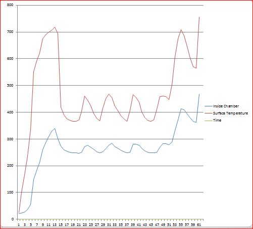
Following is the graph showing the Inside temperature and outside surface temperature of pyrolysis chamber with respect to time.

Trial outcomes-
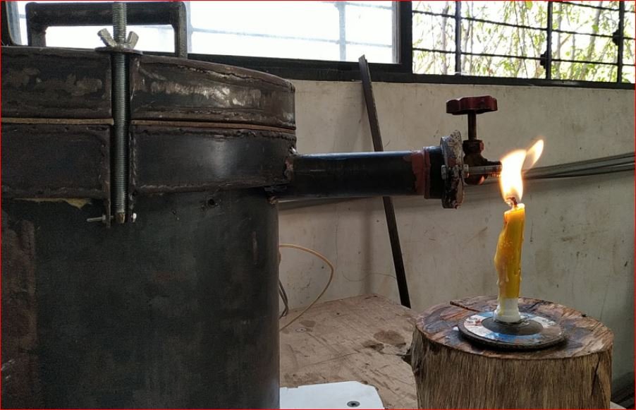
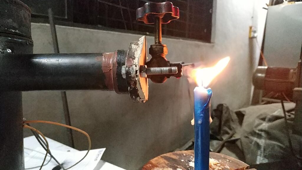
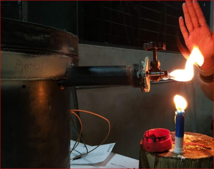
- In this trial drying and pyrolysis observed also flame generated at the tail of chimney where orifice of 6 mm diameter installed by using candle as external source to start combustion of the pyrolysis gases.
- This trial was also performed to understand the temperature ranges and heater performance.
- The pyrolysis chamber also tested with no leakage found. This trial was aimed at testing the prototype system only.
- Trial 2 – Trial on 3 Dry Pads
Following is the result and observations table along with the comments.
| Trial 2 Dry Pads Date – 15/12/2018 and 16/12/2018 Dry Pads No. of Pads- 3 | Weight of Pads (With Cover) ( Before Incineration) 1. Sample S1 – 6.30 gms 2. Sample S2 – 6.30 gms 3. Sample S3 – 6.30 gms | Weight of Pads (After Incineration) 1. S1 – 1.38 gms 2. S2 – 1.44 gms 3. S3 – 1.38 gms | Total Trial Time – 121 min. Total Heater On Time – 20 min. 30 sec. | ||||
| Inside Chamber | Surface Temperature | Time | Outer chamber Temperature | Set Temperatures | Heaters Status | Comments | Avg |
| 21 | 25 | 11:15 | 27 | 250 | On | 23 | |
| 23 | 101 | 11:16 | 27 | 250 | On | 62 | |
| 28 | 166 | 11:17 | 250 | On | 97 | ||
| 37 | 236 | 11:18 | 250 | On | 136.5 | ||
| 56 | 336 | 11:19 | 28.5 | 250 | On | Gas Started | 196 |
| 149 | 551 | 11:21 | 30.6 | 250 | On | 350 | |
| 183 | 592 | 11:22 | 30.7 | 250 | On | 387.5 | |
| 213 | 622 | 11:22:30 | 250 | On | 417.5 | ||
| 260 | 674 | 11:23 | 32 | 250 | Off | 467 | |
| 287 | 689 | 11:23:15 | 32.2 | 250 | Off | 488 | |
| 309 | 700 | 11:23:30 | 32.5 | 250 | Off | 504.5 | |
| 330 | 706 | 11:24 | 32.7 | 250 | Off | Yellowish Red Flame started | 518 |
| 340 | 718 | 11:28 | 42.3 | 250 | Off | 529 | |
| 302 | 694 | 11:34 | 52 | 250 | Off | 498 | |
| 273 | 418 | 11:42 | 54.8 | 250 | Off | 345.5 | |
| 260 | 390 | 11:45 | 63.1 | 250 | Off | Bluish Flame Burning (Breaking) | 325 |
| 254 | 375 | 11:47 | 250 | Off | 314.5 | ||
| 251 | 370 | 11:48 | 250 | Off | Gases flow and Flame Contnd. | 310.5 | |
| 249 | 366 | 11:49 | 250 | On | 307.5 | ||
| 248 | 365 | 11:49:30 | 250 | On | 306.5 | ||
| 247 | 372 | 11:50 | 250 | On | 309.5 | ||
| 250 | 404 | 11:51 | 250 | Off | 327 | ||
| 271 | 460 | 11:52 | 250 | Off | 365.5 | ||
| 277 | 445 | 11:56 | 250 | Off | Gases flow and Flame Breaking Valve Closed | 361 | |
| 270 | 424 | 11:58 | 250 | Off | Valve Opened Slow Gas flow | 347 | |
| 261 | 396 | 12:01 | 250 | Off | Gray Color gases Coming ( Breaking Flow) | 328.5 | |
| 253 | 377 | 12:04 | 250 | Off | Same as above | 315 | |
| 248 | 368 | 12:05 | 250 | On | Same as above | 308 | |
| 252 | 415 | 12:06 | 250 | Off | Same as above | 333.5 | |
| 264 | 451 | 12:07 | 250 | Off | Same as above | 357.5 | |
| 277 | 469 | 12:09 | 250 | Off | Same as above | 373 | |
| 285 | 455 | 12:11 | 250 | Off | Same as above | 370 | |
| 272 | 422 | 12:15 | 250 | Off | Valve Closed | 347 | |
| 265 | 405 | 12:17 | 250 | Off | Valve Opened Breaking Gas flow | 335 | |
| 258 | 387 | 12:19 | 250 | Off | 322.5 | ||
| 253 | 375 | 12:21 | 250 | Off | 314 | ||
| 249 | 366 | 12:22 | 250 | Off | Increased Gases density | 307.5 | |
| 251 | 408 | 12:24 | 250 | Off | Continuos Gas flow with high velocity visual Observations | 329.5 | |
| 280 | 466 | 12:26 | 250 | Off | Increased Gases density | 373 | |
| 281 | 454 | 12:28 | 250 | Off | 367.5 | ||
| 277 | 437 | 12:30 | 250 | Off | 357 | ||
| 265 | 401 | 12:34 | 250 | Off | Blackish gray Gases with breaking Flow | 333 | |
| 256 | 381 | 12:37 | 250 | Off | 318.5 | ||
| 251 | 370 | 12:39 | 250 | Off | Reduced gas flow | 310.5 | |
| 249 | 366 | 12:39:45 | 250 | On | 307.5 | ||
| 248 | 371 | 12:40 | 250 | On | 309.5 | ||
| 251 | 411 | 12:41 | 250 | Off | Very low dense gas flow with high velocity | 331 | |
| 269 | 458 | 12:42 | 250 | Off | 363.5 | ||
| 282 | 460 | 12:44 | 250 | Off | Increased Gases flow rate and medium dense | 371 | |
| 282 | 458 | 12:45 | 250 | Off | 370 | ||
| 279 | 448 | 12:46 | 350 | On | 363.5 | ||
| 288 | 502 | 12:47 | 350 | On | Increased gas flow and velocity, more continuos | 395 | |
| 331 | 609 | 12:49 | 350 | On | 470 | ||
| 371 | 675 | 12:50 | 350 | Off | 523 | ||
| 413 | 708 | 12:51 | 350 | Off | Grayeish white flame burning contin. | 560.5 | |
| 410 | 685 | 12:53 | 350 | Off | Valve Closed | 547.5 | |
| 395 | 646 | 12:55 | 350 | Off | Valve opened, very slow gas coming | 520.5 | |
| 379 | 603 | 12:57 | 350 | Off | 491 | ||
| 366 | 571 | 12:59 | 350 | Off | 468.5 | ||
| 363 | 564 | 13:00 | 450 | On | Gases stopped | 463.5 | |
| 469 | 756 | 13:13 | 450 | On | Continuos Flame and condensed liquid at chimney | 612.5 | |
| 13:16 | Off | #DIV/0! |
Following is the graph of temperatures with respect to time.
Trial Outcomes –
- The average temperature difference observed of 150 degree Celsius during the trial between pyrolysis chamber surface and center.
- Pyrolysis temperature range testing is started for dry sanitary pads which will be reference for further trials.
- Burning of gases and flame observed during the trials.
- It is confirmed that pyrolysis is happening with the 3 dry pads of weight 18.90 gm.
- The remaining material as ash is 4.2 gm.
- Next trial required to perform for checking electricity consumption for complete pyrolysis of dry pads.
- Trial 3 – Trial on 3 dry pads
| Trial 3 Dry Pads Date – 17/12/2018 Pads – whisper ultra dry No. of Pads- 3 | Weight of Pads (With Cover) ( Before Incineration) 1. Sample S1 – 5.71 gm. 2. Sample S2 – 5.75 gm. 3. Sample S3 – 5.75 gm. Total Weight – 17.21 gm. | Weight of Pads (After Incineration) 1. S1 – 0.85 gm. 2. S2 – 0.78 gm. 3. S3 – 0.77 gm. Total Weight – 2.41 gm. | Total Heater Run Time – 14 min. 45 sec. | |||
| Inside Chamber | Surface Temperature | Time 1 | Time | Set Temperatures | Heaters Status | Comments |
| 23 | 26 | 0 | 13:00 | 450 | On | Valve closed |
| 23 | 39 | 0.5 | 13:00:30 | 450 | On | |
| 23 | 51 | 1 | 13:01 | 450 | On | |
| 24 | 68 | 1.5 | 13:01:30 | 450 | On | |
| 25 | 98 | 2 | 13:02 | 450 | On | |
| 28 | 133 | 2.5 | 13:02:30 | 450 | On | |
| 35 | 193 | 3 | 13:03 | 450 | On | |
| 43 | 242 | 3.5 | 13:03:30 | 450 | On | |
| 54 | 301 | 4 | 13:04 | 450 | On | Valve Open , Gas Started coming out |
| 106 | 458 | 5 | 13:05 | 450 | On | |
| 170 | 566 | 6 | 13:06 | 450 | On | |
| 246 | 660 | 7 | 13:07 | 450 | On | Gases coming slowly |
| 300 | 722 | 8 | 13:08 | 450 | On | Flame Started, Bluish Fame |
| 379 | 803 | 9 | 13:09 | 450 | On | Gases and flame contnd. Without condensation |
| 429 | 861 | 10 | 13:10 | 450 | On | |
| 451 | 880 | 10.5 | 13:10:30 | 450 | Off | |
| 495 | 905 | 11 | 13:11 | 450 | Off | |
| 499 | 896 | 12 | 13:12 | 450 | Off | Gases slow down, flame braking |
| 492 | 873 | 13 | 13:13 | 450 | Off | |
| 471 | 817 | 14 | 13:14 | 450 | Off | Breaked gas flow |
| 459 | 785 | 15 | 13:15 | 450 | Off | |
| 450 | 755 | 16 | 13:16 | 450 | On | Valve closed |
| 475 | 780 | 20 | 13:20 | 450 | Off | Valve open, flame started, Yellowish green flame, Breaking gas flow |
| 448 | 709 | 23 | 13:23 | 450 | Off | |
| 451 | 739 | 25 | 13:25 | 450 | Off | Gas flow slightly increased, flame proppogating |
| 477 | 764 | 27 | 13:27 | 450 | Off | Gases coming slowly, breaked flow, flame starting |
| 455 | 708 | 30 | 13:30 | 450 | Off | Gas slow down |
| 449 | 695 | 31 | 13:31 | 450 | On | Gases very much slow down |
| 32 | 13:32 | 450 | No Electricity | Flame burning, slow down gases burning flame | ||
| 33 | 13:33 | 450 | No Electricity | |||
| 37 | 13:37 | 450 | No Electricity | |||
| 41 | 13:41 | 450 | No Electricity | Gases coming very slow,too slow, burning by candle | ||
| 47 | 13:47 | 450 | No Electricity | Very slow and negligible gas flow | ||
Following is the graph of temperatures with respect to time.

Trial Outcomes –
- Heaters run time found 14 min. 45 sec. that is 1 kw
- Complete pyrolysis observed in this trial since the ash remained is 1/2 by weight as compared with previous trial.
- Next trial need to perform for increased no. of pads.
- Trial 4 – Trial on 4 dry pads
| Trial 4 Dry Pads Date – 02/01/2019 Dry Pads No. of Pads- 4 | Weight of Pads (With Cover) ( Before Incineration) 1. Sample S1 – 7.70 gms 2. Sample S2 – 7.82 gms 3. Sample S3 – 7.60 gms 4. Sample S4 – 7.47 gms Total Weight – 30.59 gms | Weight of Pads (After Incineration) Total Weight – 3.97 gms Percentage residues – 12.9781 % | Total heaters run time = 47 min. | ||||
| Inside Chamber | Surface Temperature | Time 1 | Set Temperatures | Heaters Status | Comments | Heatrs Run Time | Time |
| 30 | 33 | 0 | 450 | On | 15:45 | ||
| 30 | 115 | 3 | 450 | On | 15:48 | ||
| 40 | 243 | 5 | 450 | On | 15:50 | ||
| 70 | 398 | 7 | 450 | On | 15:52 | ||
| 89 | 460 | 9 | 450 | On | Gas satrted | 15:54 | |
| 120 | 540 | 10 | 450 | On | Valve closed | 15:55 | |
| 146 | 570 | 11 | 450 | On | Valve opened, gas coming, No flame | 15:56 | |
| 190 | 625 | 13 | 450 | On | 15:58 | ||
| 229 | 671 | 15 | 450 | On | Low flame starting | 16:00 | |
| 249 | 686 | 16 | 450 | On | 16:01 | ||
| 277 | 718 | 18 | 450 | On | Flame started, non contn. Gases, valve closed | 16:03 | |
| 316 | 766 | 20 | 450 | On | Flame contnd. Without external support | 16:05 | |
| 353 | 804 | 22 | 450 | On | 16:07 | ||
| 388 | 834 | 24 | 450 | On | 16:09 | ||
| 422 | 862 | 26 | 450 | On | Condensed liquid coming | 16:11 | |
| 433 | 876 | 27 | 450 | On | 16:12 – 15:45 | 16:12 | |
| 448 | 891 | 29 | 450 | Off | Flam braking | 16:14 | |
| 453 | 873 | 30 | 450 | Off | Gases braking, valve closed | 16:15 | |
| 445 | 861 | 31 | 450 | On | 16:16 | ||
| 449 | 868 | 33 | 450 | Off | Flame contnd. | 16:18 | |
| 456 | 868 | 34 | 450 | Off | 16:19 | ||
| 442 | 828 | 36 | 450 | On | Flame cutting | 16:21 | |
| 446 | 837 | 38 | 450 | On | Very low flame, gases | 16:23 | |
| 457 | 851 | 39 | 500 | On | Flame contnd. | 16:24 – 16:21 | 16:24 |
| 497 | 889 | 45 | 500 | Off | 16:30 | ||
| 504 | 884 | 49 | 500 | Off | Flame braking | 16:34 | |
| 493 | 867 | 50 | 500 | On | 16:35 | ||
| 505 | 886 | 52 | 550 | On | 16:37 | ||
| 508 | 889 | 55 | 550 | On | Flame contd. Braking after long time, Dark smoke after burning | 16:40 – 16:35 | 16:40 |
| 553 | 951 | 60 | 550 | Off | Gases and condensed liquid both burning | 16:45 | |
| 546 | 934 | 61 | 600 | On | 16:46 | ||
| 548 | 941 | 63 | 600 | On | Flame trying to sustain | 16:48 | |
| 591 | 997 | 72 | 600 | On | Flame cutting | 16:57 – 16:46 | 16:57 |
| 74 | Off | Trial Over | 16:59 | ||||

Trial Outcomes –
- Total heaters run time observed 47 min. is very high as compared with previous trials.
- Ash content is 12.97 %
- Further trial required to be perform for wet or soiled sanitary pads.
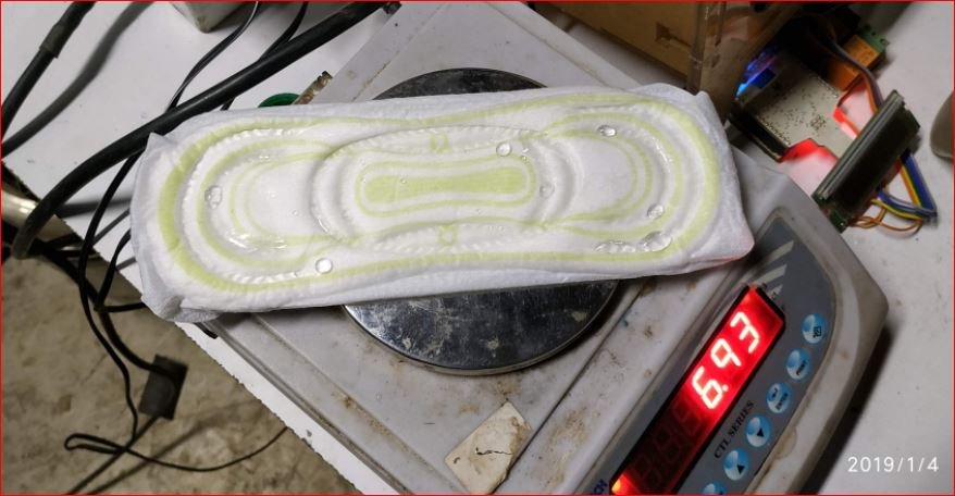
- Trial 5 – Trial on 4 wet pads
| Trial 5 Wet Pads Date – 04/01/2019 Wet Pads No. of Pads- 4 | Weight of Pads ( Before Incineration) 1. Sample S1 – 7.60 gms 2. Sample S2 – 7.78 gms 3. Sample S3 – 7.70 gms 4. Sample S4 – 7.70 gms Total Weight of Pads – 30.78 gms | Weight of Water Added (50 % by weight) 1. In S1 – 7.60 gm. 2. In S2 – 7.70 gm. 3. In S3 – 7.85 gm. 4. In S4 – 8.28 gm. Total Weight Of Water added – 31.43 gm. | Total heaters run time = 73 min. | |||||
| Time | Inside Chamber | Surface Temperature | Time 1 | Set Temperatures | Heaters Status | Comments | Heaters Run time | |
| 9:06 | 21 | 25 | 0 | 50 | On | Drying started | ||
| 9:07:30 | 21 | 66 | 1.5 | 50 | On | |||
| 9:08 | 21 | 93.5 | 2 | 50 | On | |||
| 9:08:30 | 21 | 119 | 2.5 | 50 | On | |||
| 9:09 | 22 | 152 | 3 | 50 | On | |||
| 9:09:30 | 23 | 188 | 3.5 | 50 | On | |||
| 9:10 | 25 | 220 | 4 | 50 | On | |||
| 9:10:30 | 28 | 257 | 4.5 | 50 | On | |||
| 9:11 | 31 | 290 | 5 | 50 | On | |||
| 9:11:30 | 34 | 323 | 5.5 | 50 | On | |||
| 9:12 | 39 | 354 | 6 | 50 | On | |||
| 9:12:30 | 44 | 387 | 6.5 | 50 | On | 9:12:30 – 9:06 | 06 min. 30 sec. | |
| 9:13 | 50 | 416 | 7 | 50 | Off | |||
| 9:13:30 | 58 | 445 | 7.5 | 50 | Off | |||
| 9:14 | 64 | 455 | 8 | 50 | Off | |||
| 9:14:30 | 70 | 460 | 8.5 | 50 | Off | |||
| 9:15 | 76 | 455 | 9 | 50 | Off | |||
| 9:15:30 | 82 | 453 | 9.5 | 50 | Off | |||
| 9:16 | 86 | 446 | 10 | 50 | Off | |||
| 9:16:30 | 89 | 437 | 10.5 | 50 | Off | |||
| 9:17 | 92 | 428 | 11 | 50 | Off | |||
| 9:17:30 | 93 | 417 | 11.5 | 50 | Off | |||
| 9:18 | 94 | 405 | 12 | 50 | Off | |||
| 9:18:30 | 95 | 400 | 12.5 | 50 | Off | |||
| 9:19 | 96 | 391 | 13 | 50 | Off | |||
| 9:19:30 | 97 | 382 | 13.5 | 50 | Off | |||
| 9:20 | 97 | 373 | 14 | 50 | Off | |||
| 9:20:30 | 97 | 364 | 14.5 | 50 | Off | |||
| 9:21 | 98 | 357 | 15 | 50 | Off | |||
| 9:21:30 | 98 | 349 | 15.5 | 50 | Off | |||
| 9:22 | 98 | 342 | 16 | 50 | Off | |||
| 9:22:30 | 98 | 334 | 16.5 | 50 | Off | |||
| 9:23 | 98 | 323 | 17 | 50 | Off | |||
| 9:23:30 | 99 | 323 | 17.5 | 50 | Off | |||
| 9:24 | 99 | 316 | 18 | 50 | Off | |||
| 9:24:30 | 99 | 310 | 18.5 | 50 | Off | |||
| 9:25 | 100 | 305 | 19 | 50 | Off | |||
| 0:00 | 100 | 300 | 19.5 | 50 | Off | |||
| 9:26 | 100 | 292 | 20 | 50 | Off | |||
| 9:26:30 | 100 | 290 | 20.5 | 50 | Off | |||
| 9:27 | 100 | 285 | 21 | 50 | Off | |||
| 9:27:30 | 100 | 280 | 21.5 | 50 | Off | |||
| 9:28 | 100 | 271 | 22 | 50 | Off | |||
| 9:28:30 | 100 | 268 | 22.5 | 50 | Off | |||
| 9:29 | 100 | 267 | 23 | 50 | Off | |||
| 9:29:30 | 100 | 263 | 23.5 | 50 | Off | |||
| 9:30 | 100 | 260 | 24 | 50 | Off | |||
| 9:30:30 | 100 | 256 | 24.5 | 50 | Off | |||
| 9:31 | 100 | 251 | 25 | 50 | Off | |||
| 9:31:30 | 100 | 247 | 25.5 | 50 | Off | |||
| 9:32 | 100 | 245 | 26 | 50 | Off | |||
| 9:32:30 | 100 | 242 | 26.5 | 50 | Off | |||
| 9:33 | 100 | 238 | 27 | 50 | Off | |||
| 9:33:30 | 100 | 236 | 27.5 | 50 | Off | |||
| 9:34 | 100 | 233 | 28 | 50 | Off | |||
| 9:34:30 | 100 | 230 | 28.5 | 50 | Off | |||
| 9:35 | 99 | 227 | 29 | 50 | Off | |||
| 9:35:30 | 99 | 224 | 29.5 | 50 | Off | |||
| 9:36 | 99 | 221 | 30 | 50 | Off | |||
| 9:36:30 | 99 | 214 | 30.5 | 110 | On | |||
| 9:37 | 99 | 216 | 31 | 110 | On | |||
| 9:37:30 | 99 | 221 | 31.5 | 110 | On | |||
| 9:38 | 99 | 232 | 32 | 110 | On | |||
| 9:38:30 | 99 | 252 | 32.5 | 110 | On | |||
| 9:39 | 99 | 277 | 33 | 110 | On | |||
| 9:39:30 | 100 | 265 | 33.5 | 110 | On | |||
| 9:40 | 101 | 334 | 34 | 110 | On | Fumes started coming, moist | ||
| 9:40:30 | 103 | 372 | 34.5 | 110 | On | |||
| 9:41 | 105 | 404 | 35 | 110 | On | |||
| 9:41:30 | 108 | 432 | 35.5 | 110 | On | 9:41:30 – 9:36:30 | 05 min. | |
| 9:42 | 110 | 457 | 36 | 110 | Off | |||
| 9:42:30 | 114 | 486 | 36.5 | 110 | Off | |||
| 9:43:30 | 118 | 500 | 37.5 | 110 | Off | |||
| 9:44 | 120 | 499 | 38 | 110 | Off | Moist fumes(with droplets | ||
| 9:45:30 | 122 | 482 | 39.5 | 110 | Off | |||
| 9:47 | 122 | 455 | 41 | 110 | Off | |||
| 9:48 | 123 | 437 | 42 | 110 | Off | low Condensation contd., most fumes also coming | ||
| 9:49 | 123 | 420 | 43 | 110 | Off | |||
| 9:53 | 126 | 366 | 47 | 110 | Off | |||
| 9:54 | 127 | 354 | 48 | 110 | Off | |||
| 9:55 | 128 | 335 | 49 | 110 | Off | Low moisture, periodic condensation and exit of droplets | ||
| 9:57:30:00 | 129 | 319 | 51.5 | 110 | Off | low vapours, low fumes | ||
| 9:58:30:00 | 130 | 308 | 52.5 | 110 | Off | |||
| 10:00 | 131 | 296 | 54 | 110 | Off | |||
| 10:03:30:00 | 131 | 269 | 57.5 | 110 | Off | |||
| 10:05 | 131 | 257 | 59 | 110 | Off | Drying considerably over since no vapours, no fumes | ||
| 10:07 | 131 | 267 | 61 | 500 | On | |||
| 10:10 | 138 | 387 | 64 | 500 | On | Fumes started, very low and minor vapours | ||
| 10:11:30 | 152 | 473 | 65.5 | 500 | On | Fumes started, condensation also seen | ||
| 10:13:30 | 176 | 552 | 67.5 | 500 | On | Dense fumes | ||
| 10:16 | 216 | 635 | 70 | 500 | On | low vapours and heavy fumes | ||
| 10:20 | 310 | 730 | 74 | 500 | On | Breaking flame with low vapours and condensation | ||
| 10:24:30 | 387 | 819 | 78.5 | 500 | On | Flame breaking, condensation mix | ||
| 10:28 | 429 | 864 | 82 | 500 | On | Flame started and contnd. With condensed liquid drops | ||
| 10:31:30 | 460 | 900 | 85.5 | 500 | On | |||
| 10:34:30 | 484 | 928 | 88.5 | 500 | On | Contnd. Flame and condensed droplets | 10:34:30 – 10:06 | 31 min. 30 sec |
| 10:37:30 | 502 | 935 | 91.5 | 500 | Off | Flame contnd., no condensation | ||
| 10:41 | 504 | 922 | 95 | 500 | Off | Breaking flame. | ||
| 10:42:30 | 498 | 901 | 96.5 | 500 | On | Flame breaking, condensation mix | ||
| 10:44:16 | 495 | 898 | 98.25 | 600 | On | Breaking flame | ||
| 10:46:30 | 513 | 924 | 98.5 | 600 | On | Flame contnd.. | ||
| 10:52 | 562 | 992 | 104 | 600 | On | |||
| 10:54 | 576 | 1008 | 106 | 600 | On | Flame contnd. | ||
| 10:56 | 587 | 1023 | 108 | 600 | On | Flame braking | ||
| 10:58 | 588 | 1023 | 110 | 600 | On | valve closed | ||
| 11:00 | 589 | 1023 | 112 | 650 | On | valve opened, gas flow and flame breaking | ||
| 11:06 | 595 | 1023 | 118 | 650 | On | very low gas flow | ||
| 11:18 | 492 | 784 | 130 | 650 | On | Very low dense and breaked gas flow. | 11:18 – 10:42:30 | 24 min 30 sec |
| Trial Over | Trial Over. | |||||||
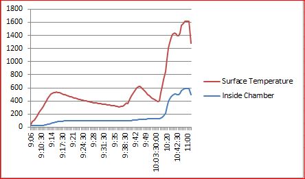
Trial Outcomes –
- In this trial both drying and pyrolysis observed. Pads made wet with same amount of water by weight.(31 gm. for 30.78 gm. weight of pads)
- Drying time observed 47 min. while pyrolysis and flame observed for 45 min.
- Heaters running time was 73 min. and energy consumption 5 kw for 4 wet pads disposal.
- From this trial we can conclude that INR 12.5 required for disposal of 1 soiled pad which is not economical or viable.
- Next trial required for increasing capacity and reducing cost per pad of disposal.
- Average temperature difference is 200 to 250 degree Celsius.
- After completing the drying process of soiled pads inside temperatures need to have in the range of 450 degree Celsius to 600 degree Celsius for complete pyrolysis.
Trial 6 – Trial on 7 wet pads
| Trial 6 Wet Pads Date – 12/01/2019 Wet Pads No. of Pads- 7 | Weight of Pads ( Before Incineration) 1. Sample S1 – 6.80 gm. 2. Sample S2 – 6.81 gm. 3. Sample S3 – 6.52 gm. 4. Sample S4 – 6.65 gm. 5. Sample S5 – 6.95 gm. 6. Sample S6 – 6.68 gm. 7. Sample S7 – 6.73 gm. Total Weight of Pads – 47.14 gm. | Weight of Water Added (50 % by weight) 1. In S1 – 6.80 gm. 2. In S2 – 6.80 gm. 3. In S3 – 6.50 gm. 4. In S4 – 6.93 gm. 5. In S5 – 6.97 gm. 6. In S6 – 6.88 gm. 7. In S7 – 6.97 gm. Total Weight Of Water added – 47.85 gm. | Weight After Incineration – 7.6 gm. | Total Heaters run time = 63 min. 35 sec. | ||||||
| Time | Inside Chamber | Surface Temperature | Time 1 | Comments | Set Temperatures | Heaters Status | Comments | Heaters run time | Average | |
| 9:45 | 15 | 18.5 | 0 | 60 | On | 16.75 | ||||
| 9:45:30 | 15 | 0.5 | On | 15 | ||||||
| 9:46 | 15 | 42 | 1 | On | 28.5 | |||||
| 9:46:30 | 15 | 49 | 1.5 | On | 32 | |||||
| 9:47 | 15 | 65 | 2 | On | 40 | |||||
| 9:47:30 | 15 | 88 | 2.5 | On | 51.5 | |||||
| 9:48 | 16 | 119 | 3 | On | 67.5 | |||||
| 9:48:30 | 17 | 146 | 3.5 | On | 81.5 | |||||
| 9:49 | 18 | 174 | 4 | On | 96 | |||||
| 9:49:30 | 21 | 213 | 4.5 | On | 117 | |||||
| 9:50 | 23 | 241 | 5 | On | 132 | |||||
| 9:50:30 | 24 | 272 | 5.5 | On | 148 | |||||
| 9:51 | 27 | 310 | 6 | On | 168.5 | |||||
| 9:51:30 | 29 | 328 | 6.5 | On | 178.5 | |||||
| 9:52 | 32 | 355 | 7 | On | 193.5 | |||||
| 9:52:30 | 35 | 381 | 7.5 | On | 208 | |||||
| 9:53 | 38 | 405 | 8 | On | 221.5 | |||||
| 9:53:30 | 42 | 425 | 8.5 | Gas started | On | Gas started | 233.5 | |||
| 9:54 | 47 | 446 | 9 | On | 246.5 | |||||
| 9:54:30 | 51 | 468 | 9.5 | On | 259.5 | |||||
| 9:55 | 56 | 490 | 10 | On | 9:55 – 9:45 | 10 min. | 273 | |||
| 9:55:30 | 60 | 504 | 10.5 | off | 282 | |||||
| 9:56 | 64 | 517 | 11 | off | 290.5 | |||||
| 9:56:30 | 69 | 520 | 11.5 | off | 294.5 | |||||
| 9:57 | 73 | 515 | 12 | off | 294 | |||||
| 9:58:30 | 80 | 460 | 13.5 | off | 270 | |||||
| 9:59 | 83 | 471 | 14 | off | 277 | |||||
| 9:59:30 | 84 | 461 | 14.5 | Gases stopped | off | Gases stopped | 272.5 | |||
| 10:01 | 87 | 453 | 16 | 90 | on | 10:01 – 10:00 | 01 min. | 270 | ||
| 10:02 | 90 | 485 | 17 | Gases coming without moisture | off | Gases coming without moisture | 287.5 | |||
| 10:04 | 98 | 493 | 19 | off | 295.5 | |||||
| 10:05 | 100 | 473 | 20 | off | 286.5 | |||||
| 10:07 | 105 | 434 | 22 | off | 269.5 | |||||
| 10:08 | 107 | 412 | 23 | No gas, no moisture | off | No gas, no moisture | 259.5 | |||
| 10:09 | 109 | 392 | 24 | off | 250.5 | |||||
| 10:11 | 110 | 348 | 26 | off | 229 | |||||
| 10:13 | 110 | 329 | 28 | off | 219.5 | |||||
| 10:20 | 110 | 256 | 35 | 120 | off | 183 | ||||
| 10:22 | 109 | 260 | 37 | on | 184.5 | |||||
| 10:24 | 109 | 349 | 39 | on | 229 | |||||
| 10:25 | 110 | 375 | 40 | Gas coming | on | Gas coming | 242.5 | |||
| 10:26 | 113 | 440 | 41 | on | 276.5 | |||||
| 10:27 | 117 | 488 | 42 | Gases flow increased | on | Gases flow increased | 10:27 – 10:21 | 06 min. | 302.5 | |
| 10:27:30 | 120 | 510 | 42.5 | off | 315 | |||||
| 10:30 | 132 | 510 | 45 | Gases fom chimney mid hole and droplets from downside tip | off | Gases fom chimney mid hole and droplets from downside tip | 321 | |||
| 10:32:30 | 135 | 459 | 47.5 | off | 297 | |||||
| 10:35 | 134 | 411 | 50 | Moisture and gases seperating(low condensation on glass) | off | Moisture and gases seperating(low condensation on glass) | 272.5 | |||
| 10:36:30 | 134 | 369 | 51.5 | off | 251.5 | |||||
| 10:41 | 132 | 320 | 56 | low gases and vapor condensation observed | off | low gases and vapor condensation observed | 226 | |||
| 10:45 | 129 | 284 | 60 | 150 | on | 206.5 | ||||
| 10:46 | 128 | 276 | 61 | on | 202 | |||||
| 10:47 | 128 | 291 | 62 | on | 209.5 | |||||
| 10:50 | 136 | 456 | 65 | more gases started | on | more gases started | 10:50 – 10:45 | 05 min. | 296 | |
| 10:54 | 150 | 553 | 69 | off | 351.5 | |||||
| 10:58 | 160 | 510 | 73 | Chimney tip changed | off | Chimney tip changed | 335 | |||
| 11:02 | 156 | 264 | 77 | off | 210 | |||||
| 11:05 | 157 | 369 | 80 | no gas, no vapors | off | no gas, no vapors | 263 | |||
| 11:07 | 156 | 367 | 82 | on | 261.5 | |||||
| 11:10 | 158 | 467 | 85 | on | 312.5 | |||||
| 11:12 | 162 | 502 | 87 | condensed drops coming no gas | on | condensed drops coming no gas | 11:12 – 11:06 | 06 min. | 332 | |
| 11:14 | 175 | 510 | 89 | gas without moisture | off | gas without moisture | 342.5 | |||
| 11:16 | 182 | 543 | 91 | off | 362.5 | |||||
| 11:18 | 184 | 495 | 93 | off | 339.5 | |||||
| 11:21 | 183 | 433 | 96 | 200 | on | 308 | ||||
| 11:25:35 | 192 | 534 | 100.5 | on | 11:25:35 – 11:21 | 04 min. 35 sec. | 363 | |||
| 11:27:30 | 200 | 590 | 102.5 | off | 395 | |||||
| 11:30 | 215 | 550 | 105 | no gas, no vapors | off | no gas, no vapors | 382.5 | |||
| 11:32 | 215 | 525 | 107 | on | 370 | |||||
| 11:36:30 | 227 | 617 | 111.5 | on | 422 | |||||
| 11:41 | 258 | 722 | 116 | gases started | on | gases started | 490 | |||
| 11:43 | 269 | 745 | 118 | gas flow increased | on | gas flow increased | 507 | |||
| 11:45 | 286 | 769 | 120 | flame starting, condensation happens and drops at 1st hole observed | on | flame starting, condensation happens and drops at 1st hole observed | 527.5 | |||
| 11:52:30 | 348 | 837 | 127.5 | Flame short breaking | on | Flame short breaking | 592.5 | |||
| 11:56 | 375 | 877 | 131 | on | 626 | |||||
| 12:02:30 | 405 | 911 | 137.5 | flame sustaining very long but gases breaking | on | flame sustaining very long but gases breaking | 658 | |||
| 12:08 | 424 | 916 | 143 | on | 670 | |||||
| 12:14 | 448 | 939 | 149 | on | 693.5 | |||||
| 12:19 | 463 | 962 | 154 | on | 712.5 | |||||
| 12:26 | 482 | 974 | 161 | on | 728 | |||||
| 12:30 | 494 | 987 | 165 | on | 740.5 | |||||
| 12:33 | 499 | 995 | 168 | flame breaking | on | flame breaking | 12:33 – 11:31 | 02 min. | 747 | |
| 12:39 | 500 | 979 | 174 | off | 739.5 | |||||
| 12:40 | 501 | 973 | 175 | no condensation | 550 | on | no condensation | 737 | ||
| 12:47 | 514 | 1000 | 182 | on | 757 | |||||
| 12:49 | 518 | 1008 | 184 | on | 763 | |||||
| 12:52 | 524 | 1015 | 187 | on | 769.5 | |||||
| 12:54 | 527 | 1020 | 189 | on | 773.5 | |||||
| 12:59 | 537 | 1023 | 194 | on | 12:59 – 12:40 | 19 min. | 780 | |||
| 13:06 | 551 | 1023 | 201 | off | 787 | |||||
| 13:08 | 544 | 1023 | 203 | on | 783.5 | |||||
| 13:13 | 549 | 1023 | 208 | on | 786 | |||||
| 13:17 | 556 | 1023 | 212 | trial end | 500 | on | trial end | 13:17 – 13:07 | 10 min. | 789.5 |

Trial Outcomes –
- Trial on 7 wet or soiled pads using water performed.
- Trial completed in 3 hour 32 minutes.
- Heaters running time is 63 minutes which consumed 4 kw. electricity.
- With loading 7 wet pads energy cost per pad was INR 5.5.
- This trial is an optimization as compared with previous trial.
- During the trial condensed grease like liquid noticed at the tail of chimney.
- T joint was placed at the end of chimney with cotton on bottom side for absorbing condensate while other side of the T-joint was exit of gas and starting of flame.
- The drying time was around 155 minutes out of 312 minutes during trial.
Brainstorming and analysis of trials data done with Dr. Arun Dixit, Mr. Ameya Kulkarni and team.
Suggestions and modifications received during discussion –
- To make hollow space at the center of inside pyrolysis chamber to reduce drying time by shortening the heat transfer length.
- To limit or specify the capacity of the current prototype to 7 pads disposal at maximum per batch.
- To work on reducing energy consumption per pad for disposal.
Trial 7 – Trial on 7 wet pads
| Trial 7 Wet Pads Date – 19/01/2019 Wet Pads No. of Pads- 07 | Weight of Pads ( Before Incineration) 1. Sample S1 – 6.84 gms 2. Sample S2 – 7.00 gms 3. Sample S3 – 6.87 gms 4. Sample S4 – 6.76 gms 5. Sample S5 – 6.77 gms 6. Sample S6 – 6.84 gms 7. Sample S7 – 6.66 gms Total Weight of Pads – 47.74 gms | Weight of Water Added (approx. 50 % by weight) 1. In S1 – 6.78 gms 2. In S2 – 7.38 gms 3. In S3 – 7.16 gms 4. In S4 – 6.76 gms 5. In S5 – 6.80 gms 6. In S6 – 6.76 gms 7. In S7 – 6.89 gms Total Weight Of Water added – 48.53 gms | ||||
| Time | Inside Chamber Temperature | Surface Temperature | Heaters Run time | Set Temperatures | Heaters Status | Comments |
| 15:10 | 30 | 34 | 60 | on | ||
| 15:12 | 30 | 99 | ||||
| 15:14 | 33 | 200 | ||||
| 15:15 | 36 | 270 | ||||
| 15:16 | 41 | 350 | ||||
| 15:18 | 54 | 453 | 8 min | |||
| 15:19 | 65 | 507 | off | |||
| 15:21 | 78 | 496 | very few gases andvapors | |||
| 15:23 | 89 | 443 | ||||
| 15:28 | 99 | 329 | ||||
| 15:31 | 101 | 295 | 120 | |||
| 15:32 | 101 | 291 | on | |||
| 15:50 | 139 | 365 | ||||
| 15:52 | 138 | 348 | ||||
| 15:53 | 138 | 332 | ||||
| 15:54 | 138 | 327 | 160 | |||
| 16:00 | 158 | 620 | 28 min | off | gases with moisture | |
| 16:05 | 178 | 593 | ||||
| 16:09 | 180 | 490 | ||||
| 16:15 | 172 | 381 | ||||
| 16:20 | 165 | 329 | gases and vapors stopped | |||
| 16:23 | 161 | 309 | 180 | |||
| 16:24 | 160 | 309 | on | |||
| 16:35 | 163 | 424 | very low gases coming | |||
| 16:37 | 167 | 574 | 13 min | off | ||
| 16:40 | 198 | 630 | ||||
| 16:45 | 209 | 576 | ||||
| 16:46 | 209 | 542 | 600 | |||
| 16:47 | 209 | 492 | on | |||
| 16:50 | 209 | 576 | ||||
| 16:52 | 216 | 627 | ||||
| 16:56 | 260 | 766 | gases increased | |||
| 17:00 | 300 | 836 | flame starting | |||
| 17:03 | 325 | 872 | ||||
| 17:07 | 352 | 905 | ||||
| 17:13 | 393 | 958 | ||||
| 17:22 | 442 | 1006 | ||||
| 17:31 | 470 | 1023 | ||||
| 17:38 | 462 | 1023 | ||||
| 17:41 | 461 | 1023 | ||||
| 17:44 | 455 | 998 | flame breaking | |||
| 17:47 | 435 | 868 | ||||
| 17:50 | 413 | 764 | 63 min | heaters fused | Gases stopped completely |
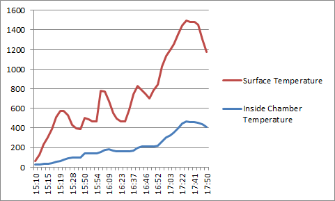
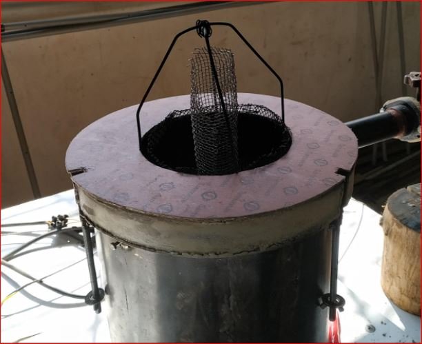
- As per discussion wet pads loading cage is modified by placing hollow cylinder at the center made up of wire mesh.
- Trial started on 7 wet pads.
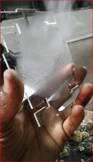
- During trial drying observed for around 80 minutes and gases started coming out without moisture.
- Moisture in gases checked by placing transparent glass in gas flow.
During this trial the IR ceramic heaters run at above maximum permissible temperatures due to which all 8 heaters fused. It was required to run the heaters at higher temperatures since, the temperature difference was 350° C during the 7 pads trial and pyrolysis temperature range achieved from was in between 450° C to 600° C.
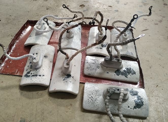
- The diagnosis of heaters fusing highlights following reasons
- Running the heaters at above maximum permissible temperature range.
- The gap between heater surface and pyrolysis chamber surface.
- Front facing arrangement of heaters with very low distance in small vicinity.
- The heaters procurement without datasheet or operating manual, etc.
Please click here to understand the operation of current prototype:
https://drive.google.com/file/d/1l6JsWDL50CpMmCwVdjW2BwBX4j7xKGPh/view?usp=sharing
Bill of Material –
| Sr. No. | Description | Material/Details | No. of Units | Material Quantity | Vendor |
| 1 | Pyrolysis chamber | MS CRCA sheet 2.5 mm thickness | 1 | 4 sq. feet | Local steel trader |
| 2 | Pyro. chamber flange | MS CRCA sheet 2.5 mm thickness | 1 | 4 sq. feet | Local steel trader |
| 3 | Pyro. chamber bottom | MS CRCA sheet 2.5 mm thickness | 1 | 2 sq. feet | Local steel trader |
| 4 | Outer shell | MS CRCA sheet 2.5 mm thickness | 1 | 5 sq. feet | Local steel trader |
| 5 | Outer shell bottom | MS CRCA sheet 2.5 mm thickness | 1 | 2 sq. feet | Local steel trader |
| 6 | Lid | MS CRCA sheet 2.5 mm thickness | 1 | 5 sq. feet | Local steel trader |
| 7 | Gasket | Compressed Asbestos jointing sheet 3 mm thick | 1 | 3 sq. feet | Mfg. by – Samsonite,Shah Rubber products Bhosari |
| 8 | Wing nut and bolts | M6* 4 inch | 4 | 4 | – |
| 9 | IR Ceramic heaters | Ceramic IR curved type 122mm*60mm*500watt* 240 V AC | 8 | 8 | BK Electricals Vashi, Navi Mumbai |
| 10 | J type industrial thermometers | J type 100 mm probe 1160 degree Celsius with module | 2 | 2 | Bombay Electricals and Engineers Pune |
| 11 | Temperature controller | Selec TC513 | 1 | 1 | Bombay Electricals and Engineers Pune |
| 12 | Solid state relay | SSR | 1 | 1 | Bombay Electricals and Engineers Pune |
| 13 | MCB | 2 pole 32A | 1 | 1 | Bombay Electricals and Engineers Pune |
| 14 | Chimney | MS Pipe – 2 inch dia. * 2 mm thick | 1 | 1 feet | Local steel trader |
Pyrolysis based sanitary napkins incinerator Version 3.2
Background –
After performing the trials and heaters burnout or fusing in V3.1, it is decided to design a new prototype considering the results of previous experiments data and understandings.
Key learning from experiments with previous prototype (v3.1)
- With available ceramic IR heaters and design it is difficult to achieve and maintain pyrolysis temperature range of above 450 degree Celsius inside the pyrolysis chamber.
- To maintain 450 degree Celsius inside the pyrolysis chamber heaters required to run by adding 250 degree Celsius temperature difference at chamber outer surface and center.
- In previous prototype (V3.1) indirect heating is used. Heat loss occurs in heating and cooling of pyrolysis chamber material.
- Due to indirect heat transfer cycle time for disposal of soiled pads increases which leads to high energy consumption.
Objectives with current prototype v3.2
- To reduce cycle time required for complete disposal of soiled pads using pyrolysis principle.
- To reduce energy consumption for given batch.
By considering above objectives for designing and developing the prototype the cost requirement of disposal per pad will also reduce.
Concept and Assumptions
- The heat required for heating of pyrolysis chamber with indirect heat transfer to soiled pads will be reduce by placing Ceramic IR heaters inside the pyrolysis chamber.
- Direct heating will reduce the heat loss and cycle time of a batch.
- The operating temperature of heaters will not exceed its maximum permissible temperature range.
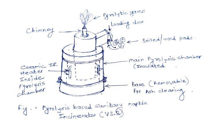
Following is the concept sketch with modifications including
- Ceramic IR heaters inside the pyrolysis chamber
- Soiled pads inlet arrangement
- Central exhaust/chimney at the top of incinerator
- Ash removal arrangement with independent bottom platform
Detailed Design
Design Considearations
- Capacity of pyrolysis chamber – 5 soiled pads when bundled
- Material – MS CRCA sheet 2.5 mm thickness
- Split design with 3 assemblies
- Base assembly – Consist of cage and bottom lid as base which is removable for ash removal.
- Main chamber assembly – Consist of pyrolysis chamber with internally mounted ceramic IR heaters. Removable outer cover with glass fibre insulation and heater mounting arrangements.
- Chimney – Consist of pyrolysis gases exaust and flame arrangement. Also having pad loading door. Chimney is also removable and a independent assembly.
- Loading cage volume – 1.871 liters
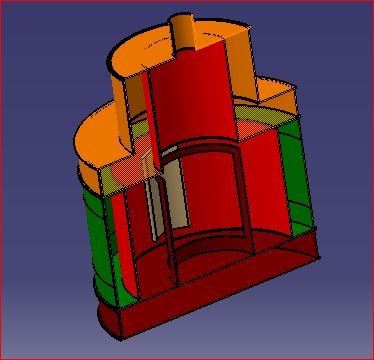
CAD and detailed drawings
- Base Assembly
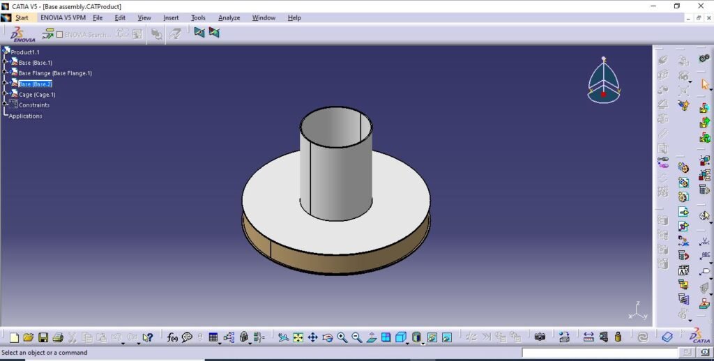
Base assembly includes-
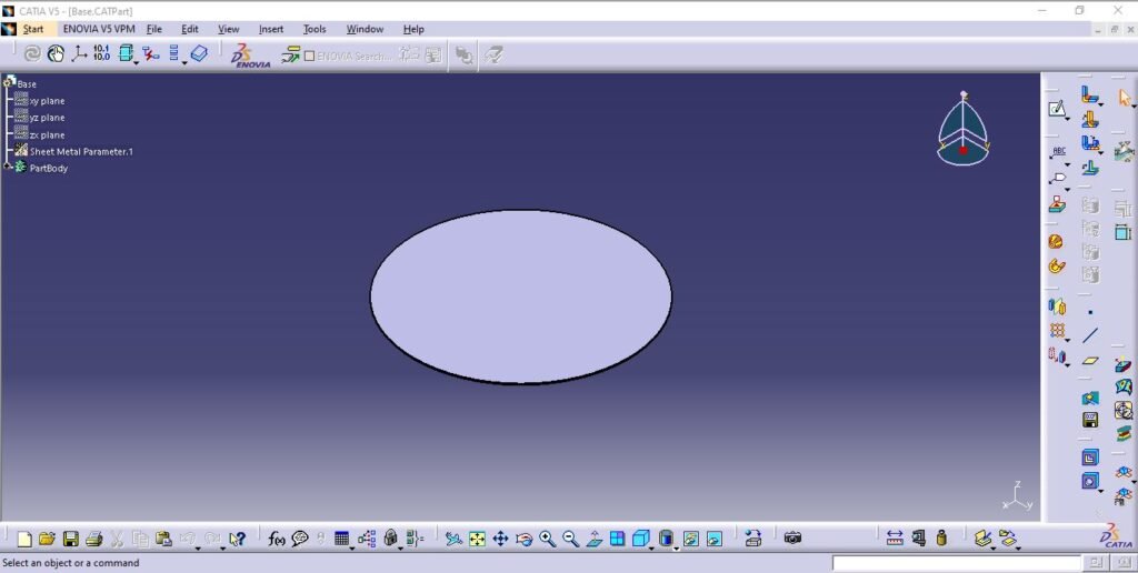
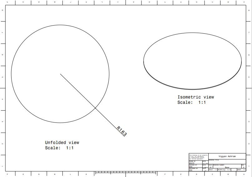
- Base plate
Two base plates are required to make complete base.
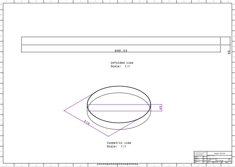
2. Base Flange
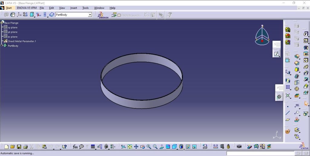
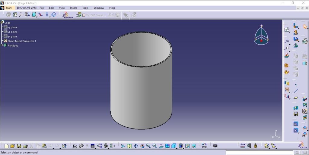
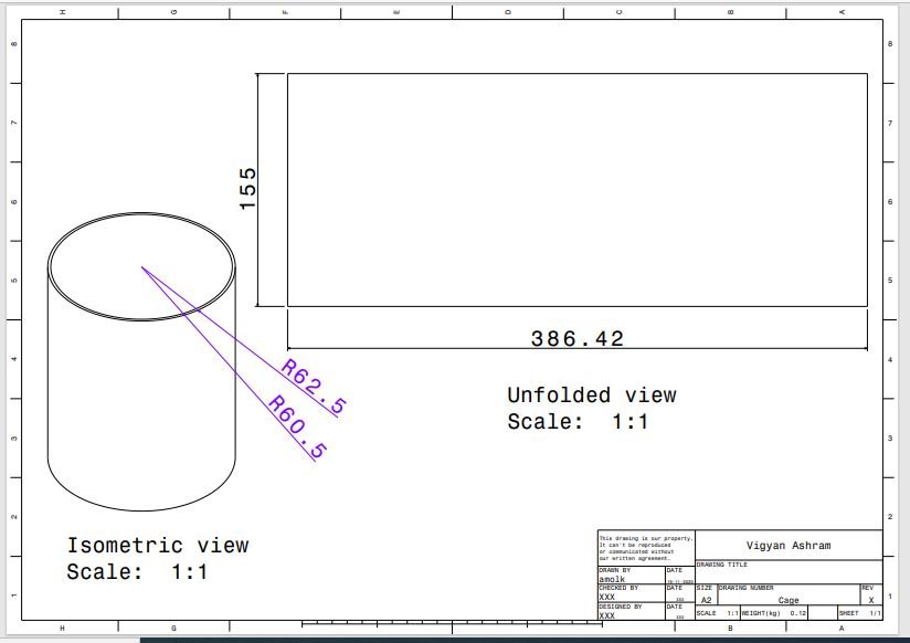
3. Cage
Cage is based on upper base plate for the purpose of loading pads.
- Main Chamber Assembly
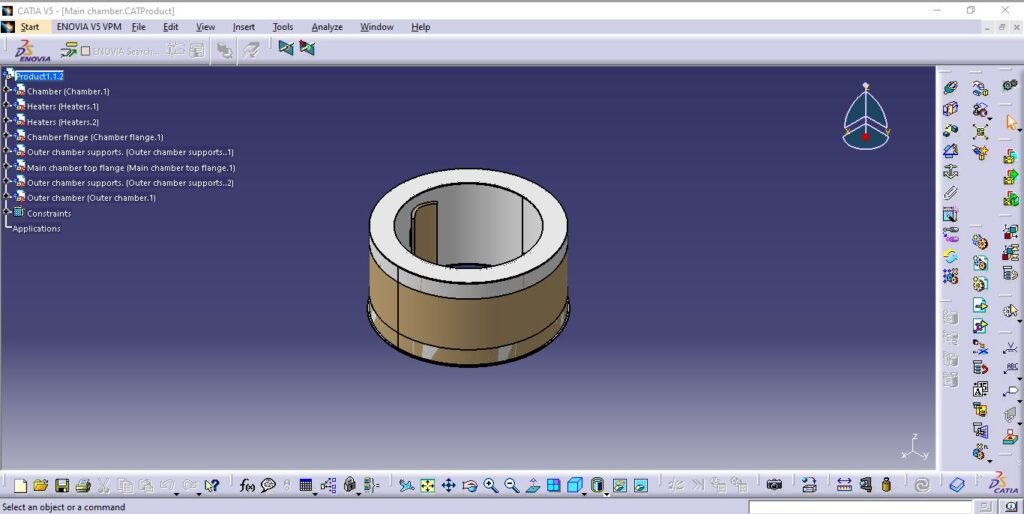
Main chamber assembly is the core of complete incinerator model which includes;
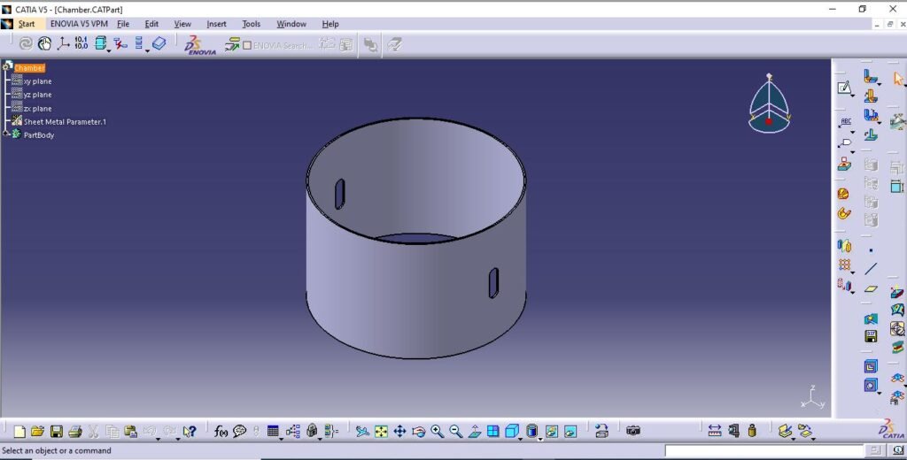
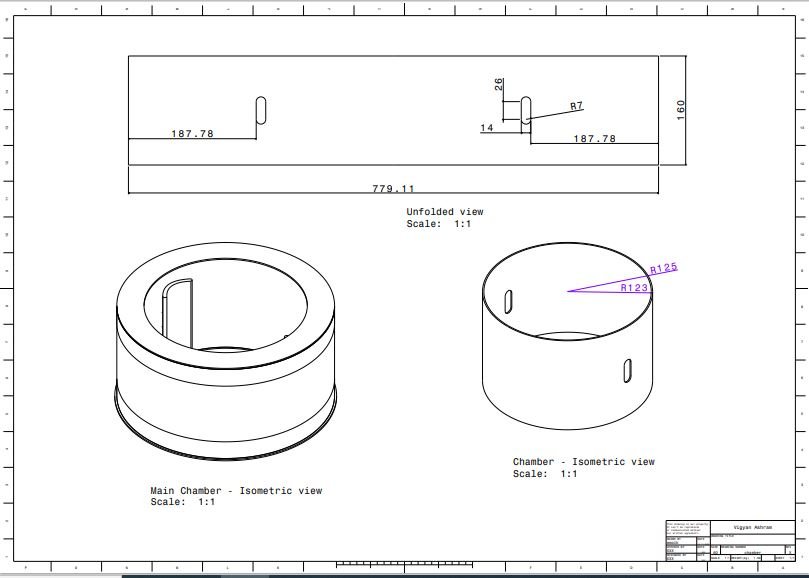
- Pyrolysis chamber
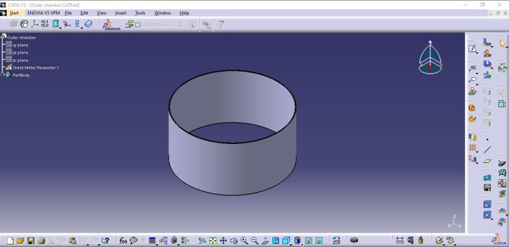
2. Outer chamber
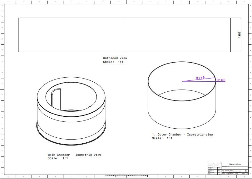
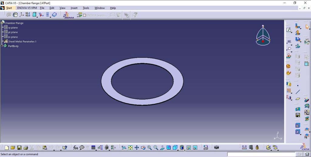
3. Chamber Flange

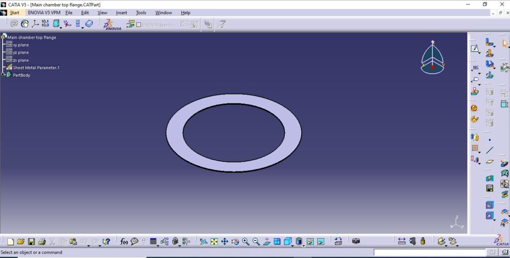
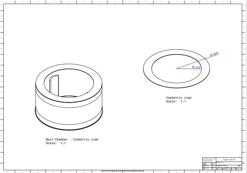
4. Main chamber top flange
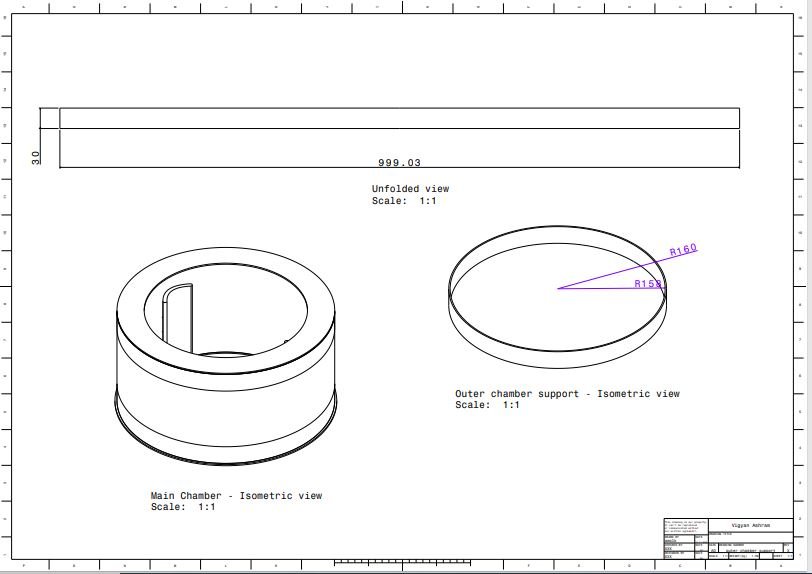
5. Outer chamber support
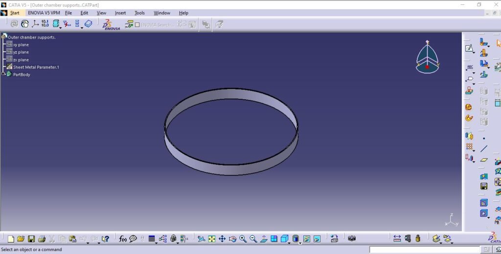
- Chimney
Chimney assembly consists of loading door, chimney outlet for pyrolysis gas escape and flame purpose. This assembly is independent which is removable and joint is sealed using gasket.
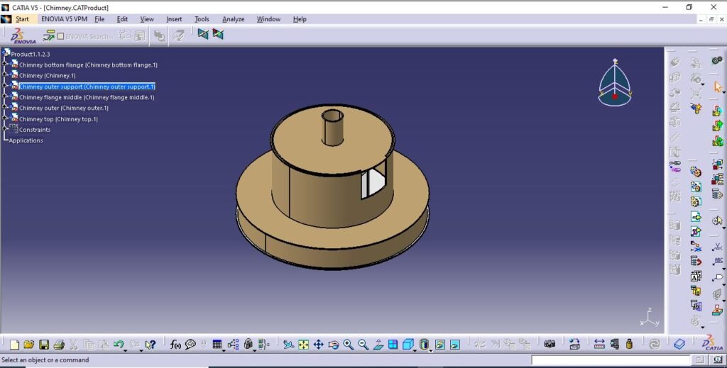
This includes;
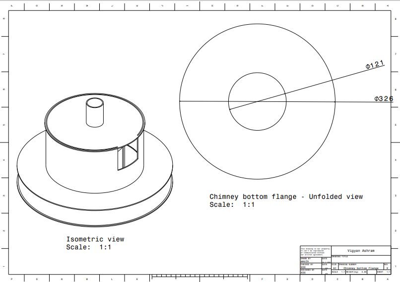
- Chimney bottom flange

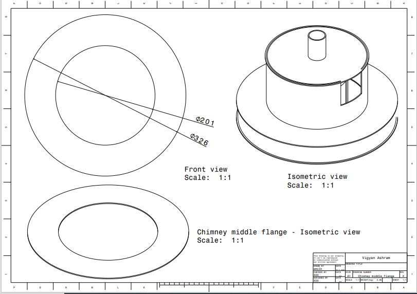
2. Chimney middle flange

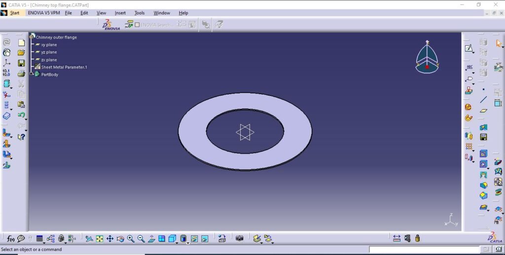
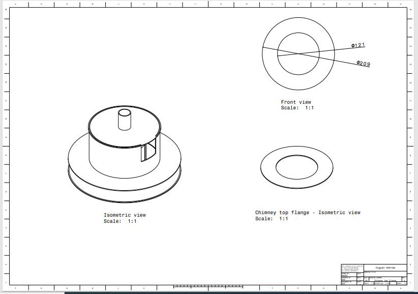
3. Chimney top flange
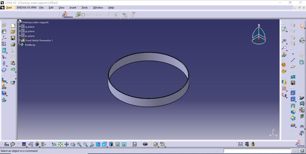
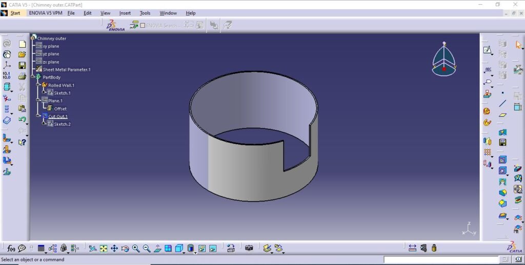
4. Chimney outer support
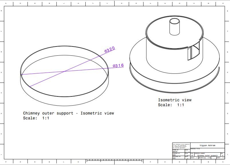
5. Chimney outer chamber
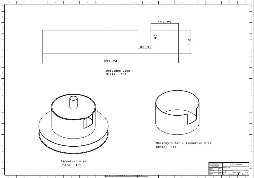
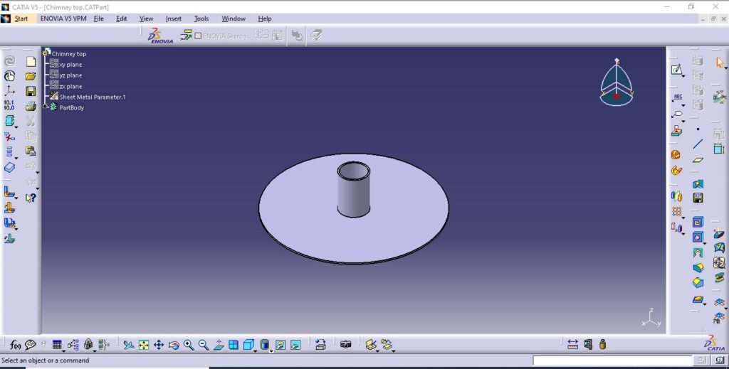
6. Chimney top
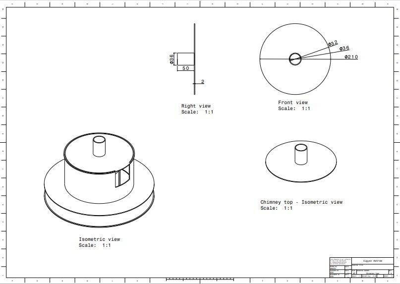
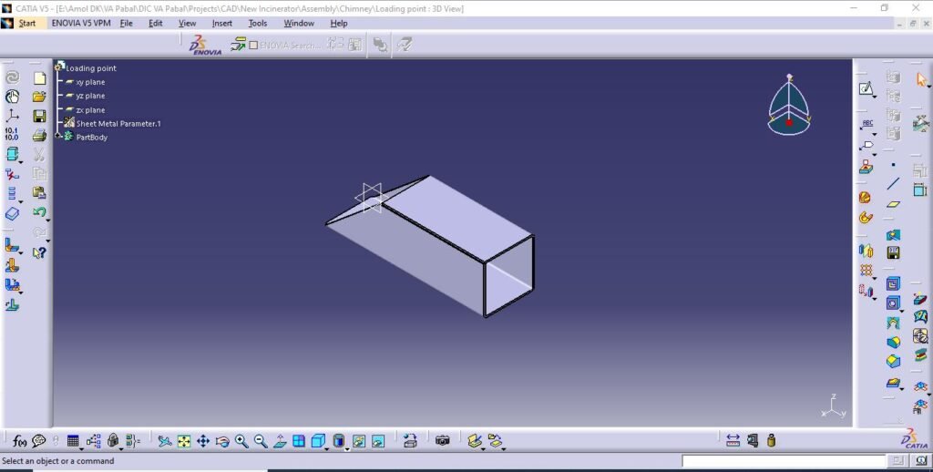
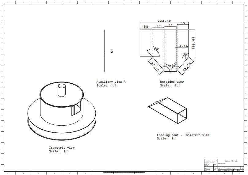
7. Loading point
Manufacturing
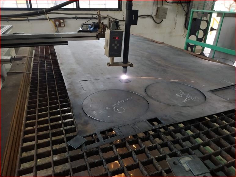
- Sheet cutting and cylindrical chambers
Using above design details and CAD models manufacturing of the prototype started. CNC plasma cutting machine and sheet metal rolling used mostly for manufacturing. Arc welding used for joining operations.
2 mm thickness MS CRCA sheet is used.
After cutting rolling operation done for making cylindrical parts like outer chamber, pyrolysis chamber, chimney outer chamber.
By using arc welding joining operations done as per CAD drawings.
- Heater mounting and main chamber assembly
Ceramic IR heaters 2 nos. mounted inside the pyrolysis chamber and the mounting surface is made leak proof using thermal sealant.
The heaters are of 500 watt each. Gap between pyrolysis chamber surface and outer chamber is filled by glass wool as an thermal insulation to avoid heat loss. Outer chamber is removable with purpose of heaters handling and maintenance.
Compressed asbestos jointing sheet gasket is used between two joining surfaces for leak proof joint.
- Chimney assembly with inlet door, chimney and loading cage
This assembly includes inlet door with wing nuts for loading of soiled sanitary pads. Central gas exhaust arrangement in top flange given as chimney where flame can be made for disposing the gases from pyrolysis.
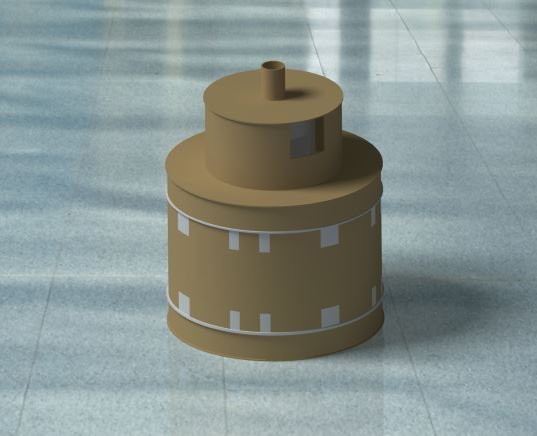
The cage is provided with perforation and open at bottom. Following image shows complete chimney assembly.
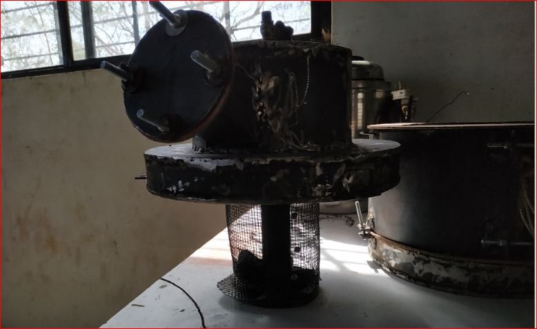
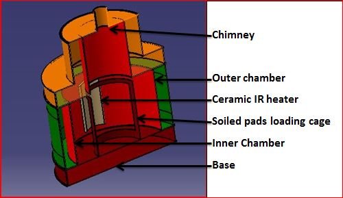
- Sanitary napkin incinerator prototype v3.2 complete assembly
Testing and Trials
- Trial 1
Trial 1st is performed as a test run without any pads or materials to check functionality of the prototype.
During this trial maximum temperature of 540 degree Celsius achieved inside the pyrolysis chamber in 35 minutes using two heaters 500 watt each.
With the result of temperature range achieved in test trial next trial on two soiled pads using water scheduled and performed.
- Trial 2
This trial is performed for two sanitary napkins soiled in water with same quantity by weight.
Initially drying of pads started and continued for 35 minutes in the temperature range of 100 degree Celsius to 160 degree Celsius. Temperatures set at 500 degree Celsius when dry gases started coming out of the chimney.
Maximum temperatures achieved of 385 degree Celsius after which temperature range started falling down. Temperatures doesn’t increased for next one hour and trial has stopped.
Diagnosis done for not raising temperature during the trial inside the pyrolysis chamber. Heaters found fused in the chamber.
After this trial it is decided to not use electrical heaters directly inside the pyrolysis chamber.
Conclusion
After performing trials on two versions it is understood that electrical heating for pyrolysis based incineration is costly and not reliable with available heaters for the v3.1 prototype design and v3.2 also.
Material of construction study is required considering optimum heat transfer for pyrolysis.
It is also decided to work on design of a prototype of gas based heating system for incinerator and recirculation of gases from pyrolysis of soiled pads.
The gas fired pyrolysis based sanitary pad incinerator concept sketch is given below.
Following is the link for downloading all DXF files for manufacturing –
https://drive.google.com/drive/folders/1Hp-5KEV8ibqz6Beb8Rt7inU6pmY7P-Bm?usp=sharing

