
One unit of composter is installed in Siddharthnagar society, Aundh, Pune. Depending on the data or feedback from that I had to design a new unit of the composter.
For that purpose, I worked with Mr. Soumitra Kulkarni sir in Nashik in their own manufacturing industry. Where I supposed to get inputs from them for designing a new system.
At first, Soumitra sir wants to go with the existing design and test it.
But I have some alternatives for that system in my mind. But to prove that which one is good first I have to go with the existing one.
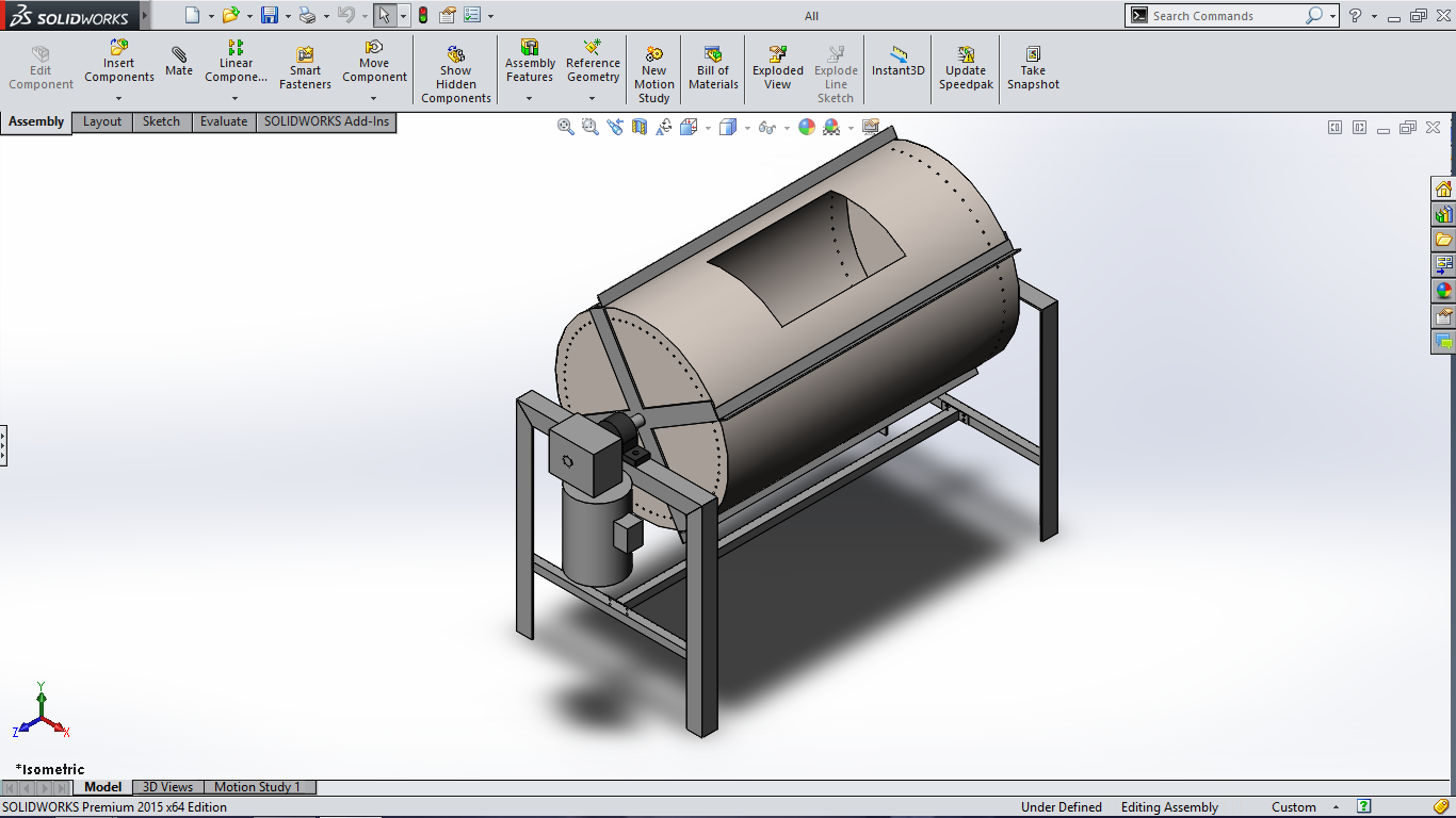
As Shubham gave me design pdf files of existing one, I create a 3D model on solid works and made a Bill of Material (BOM).
While designing a new system I focused on three major areas:-
- Ease of transportation:-
In earlier system, whole frame structure is welded, so it’s difficult to transport the unit. I designed a frame so that it can be easily dissembled and assembled.
For old system, square tube is used for frame structure. The disadvantage of that is, it’s get rusted quickly. It is not a long life solution.
So I select L-channel for the frame.
- Drum Rotating Mechanism-
It is one of the most important parameter under consideration.
The earlier system consists of a number of components on which drum rotates, like motor, gearbox & chain drive to rotate two solid MS shafts. On this shaft, four nylon rollers are fitted. For firm grip between drum and roller, rubber is fitted over nylon rubber.
As a number of components more, manufacturing dependability on them and manufacturing cycle time is more. Production becomes a lengthy process.
To avoid that I referred an arrangement like the drum is fixed on the single shaft and to rotate that shaft mechanism can be used like the direct coupling of motor and gearbox to drum shaft or chain and sprocket to connect gearbox shaft and drum shaft.
So that there should be less no of components so complexity gets reduced and manufacturing gets also easy and low cycle time.
- Motor selection:-
Existing unit runs by 1 hp motor.
So proper selection of motor needs to be done.
I was expecting inputs in these calculations from employees from Nashik but disappointed.
3D models that I made:-
- Old drum:-

Since the 3D model of existing composter unit is not available, I made it.
While creating this model I had done some modifications in the frame as using fasteners so that it can be easily dissembled and assembled. But after discussion with Yogesh(Nashik) sir, this arrangement is not suitable for long term application concluded.
Also made a BOM for ease of comparision.
Design for Metal Cylindrical Drum:-

This system is designed for the metal drum.
Its appropriate height, length, width, etc is fixed and design.
BOM is made for both M.S. drum and S.S. Drum.
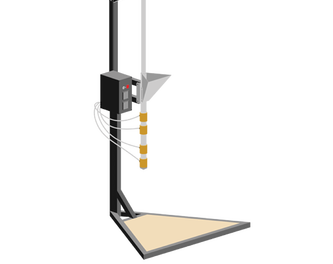
- Design for plastic Drum:
- Design for Hexagonal Drum 300 Ltr

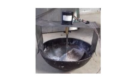
After all this process Soumitra sir gave us A mixer drum with motor and gear arrangement.
We all agree to use it as composter because its economical but problem was its worm shaft from the gearbox is missing.
We approach a gear manufacturer he promised to give it within four days. But he did not follow his words and wasted our 5 days.
Then we approached another gear manufacturer who original manufacturer of this mixer drum.
While gear is manufacturing we made perforation on the drum to 3% open area.

This project is not concluded yet.

