Society Waste Composter (Hexagonal 120 Liter Tumbler) v1.0
Background :
While working in the field of decentralized waste management by composting wet organic waste, different solutions developed in Vigyan Ashram and tested as pilot systems. These solutions are listed in the links below with all details.
Solutions developed by Vigyan Ashram –
- http://vadic.vigyanashram.blog/2019/03/11/the-madhuban-unit/
- http://vadic.vigyanashram.blog/2019/03/11/designs-for-big-composting-unit/
- http://vadic.vigyanashram.blog/2019/07/16/a-journey-towards-green-world/
With experience from these systems, it has been decided to design and develop a modified version considering the following requirements;
- Uniform mixing of waste and microbial culture
- Cost optimization
- Simple to handle and operate by user/operator
- Minimum contact with waste of an operator
- The convenience of waste loading and unloading operations
SIZE AND SHAPE SELECTION
With experiences and observations from previous models and systems, the compost mixing system (i.e. tumbler) and compost stacking system will be separate.
So, Following are considerations while selecting the shape of tumbler:
- For a selection of the shape of the composter/mixer, the main consideration is the tumbling effect for the homogeneous mixing of wet waste and microbial culture in 1:1 proportion.
- From Hexagonal shape Domestic Home composters trials, uniform mixing due to the tumbling effect observed. So, hexagonal shape is selected for the mixer.
- The current system is considered for composting the waste of 50 to 60 families per batch. So from this consideration, we will have approximately 25 kg. to 30 kg. wet waste daily. For the said quantity of waste, the same quantity of microbial culture will add for composting with 1:1 proportion by weight.
- So, for 25 kg. to 30 kg. waste and the same amount of culture volume of around 120 liters will require.
- The mixer will be motorized for reducing human efforts required to rotate the drum.
Ideation and concept sketch
The hexagonal tumbler as shown in the following sketch is decided to design by considering the above requirements.
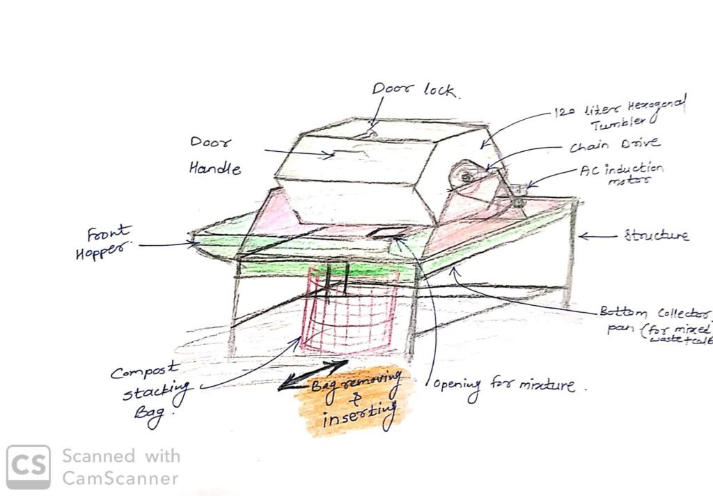
As shown in sketch the hexagonal tumbler of 120 liters will be rotated using AC induction motor as a prime mover. The tumbler will be rotated using chain drive from motor. The capacity of motor and running speed will be estimated in detail designs.
The 120 liter tumbler will be suitable for 30 Kg waste which is coming from around 50 to 60 families society in a batch. There will be space beneath the bottom hopper of compost mixer to insert compost stacking bag and collect the waste and culture mixture.
The compost mixer unit will be assembled with following systems ;
- 120 liters hexagonal tumbler.
- Frame structure
- Drive system
- Hopper, covers and chaing guard
1. Hexagonal tumbler (120 liter)
The hexagonal tumbler of 120 liters volume is decided to design and fabricate considering the advantage of its shape for homoginious mixing of wastw and microbial culture from the experience of home composter.
- Material of construction-
- MS CRCA sheet – 1.2 mm thickness
- FRP coating from inside of drum to avoid corrosion
- Stainless steel rivets for shett metal joining
- Design details
Following are the CAD models with detailed drawings of all main assemblies, sub-assemblies and single part/components.
As described above following are the assemblies classified into groups;
- Drum/Tumbler assembly
- Frame structure
- Drive system
- Hopper, covers and chain guard
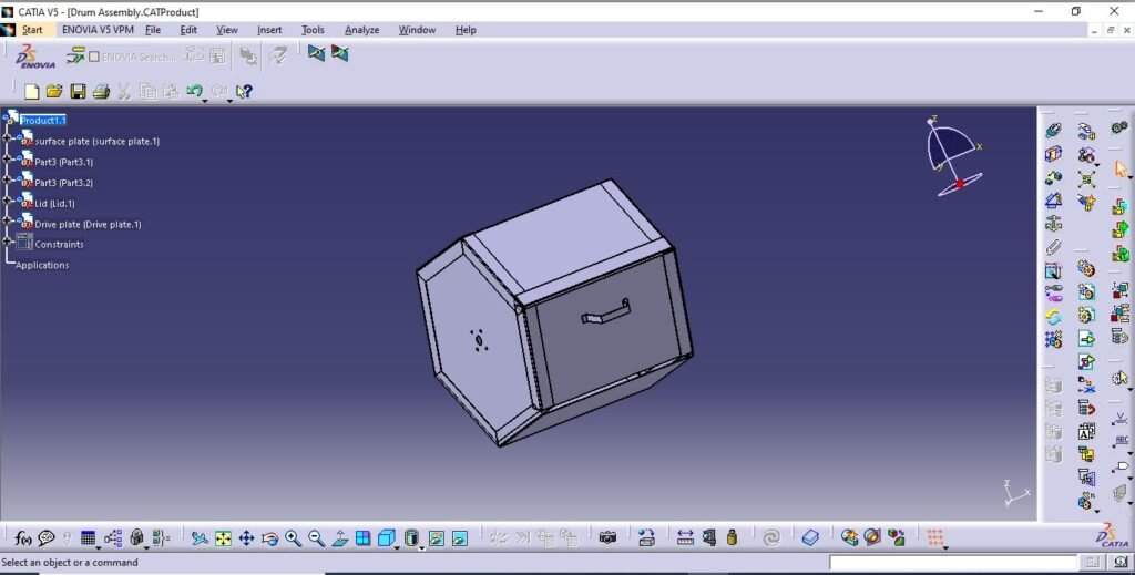
- Drum assembly
Drum assembly includes 3 components;
- Surface plate
- Lid
- Side flanges
Following is the main assembly of tumbler (CAD model)
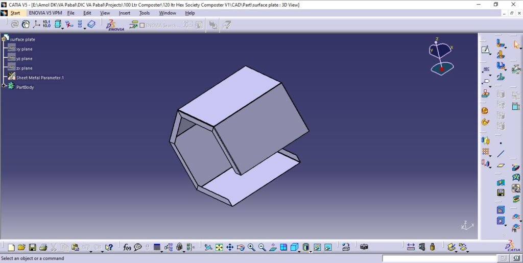
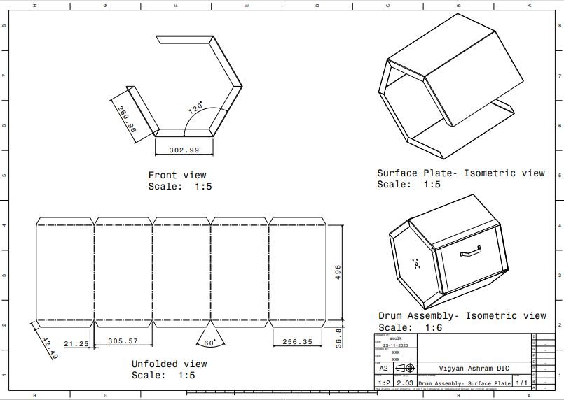
- Surface plate
Surface plate is the main outer body of the drum with 5 sides.
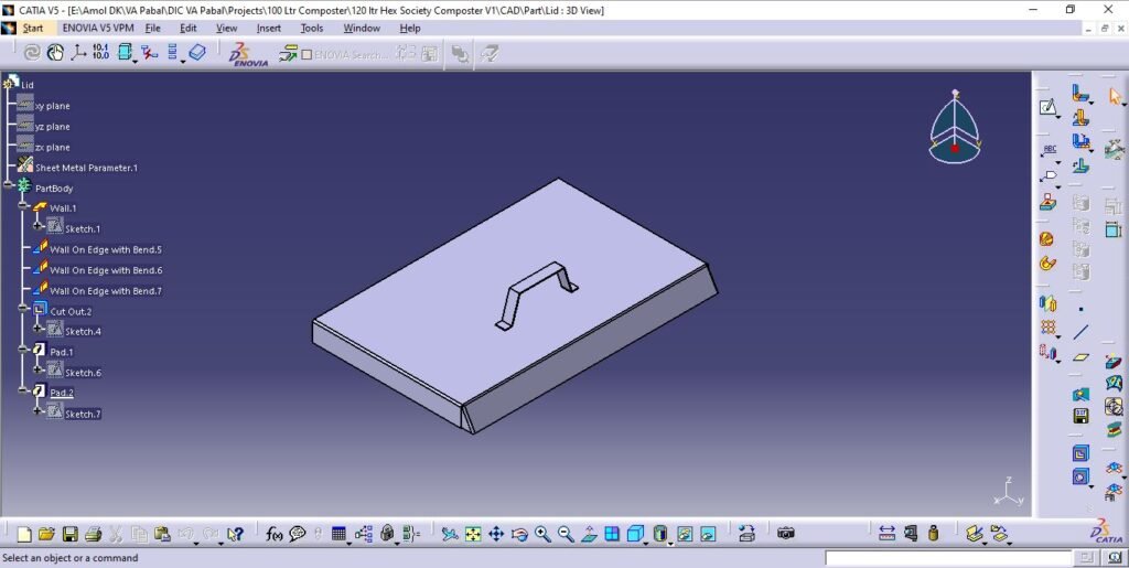
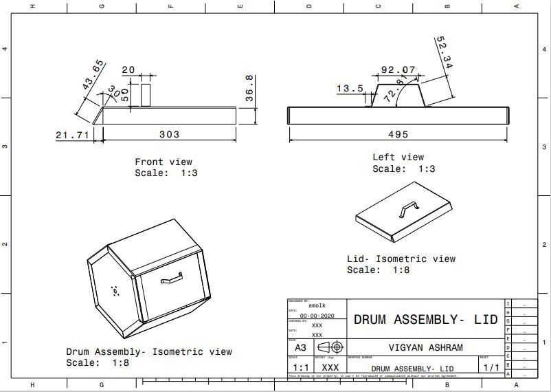
2. Lid
Lid is the 6th independent side of the tumbler hinged to the 5th side from surface plate. Lid is provided with locking arrangement for loading and unloading operations.
Handle is provided to the lid from outside to hold and operate the lid.
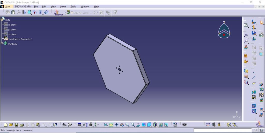
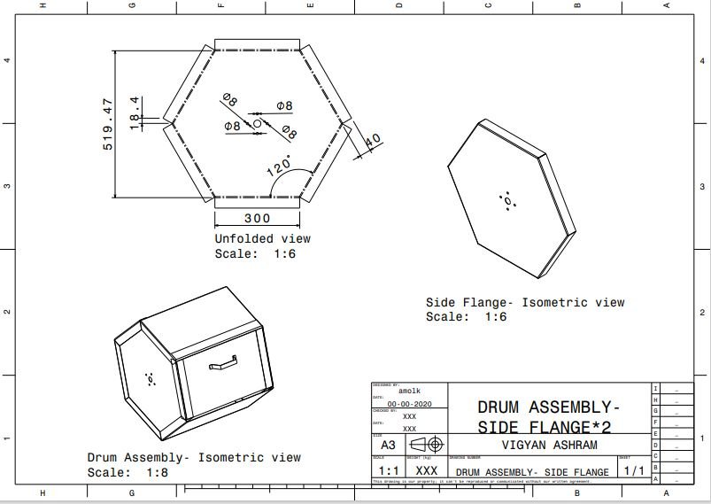
3. Side flanges
Side flanges are mounting plates to side plate with hexagonal shape. It is also having drive plates fitted from drive transmission and coated with FRP from inside.
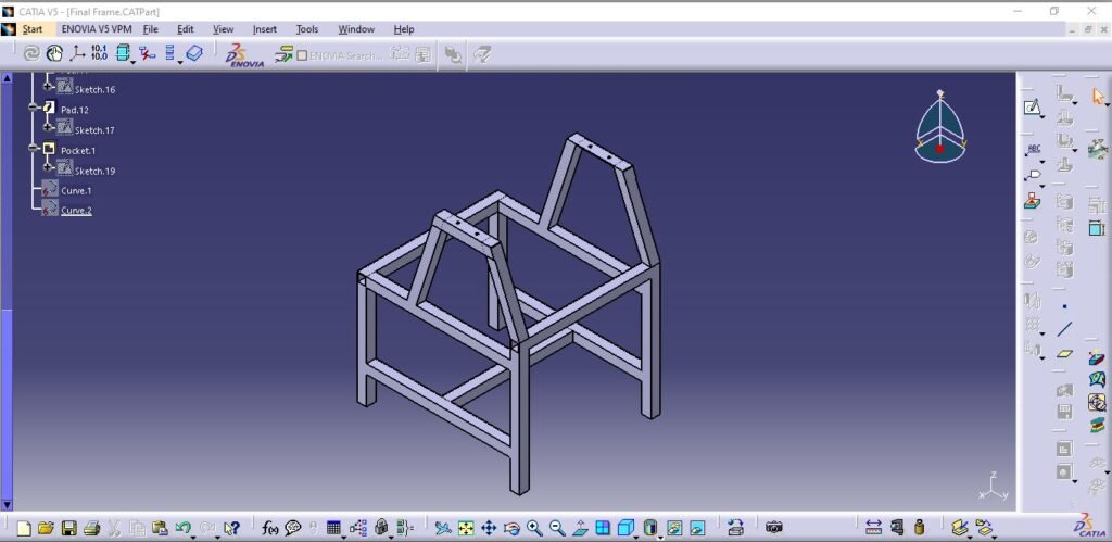
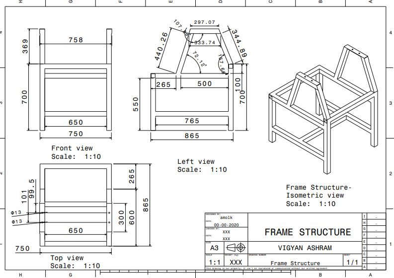
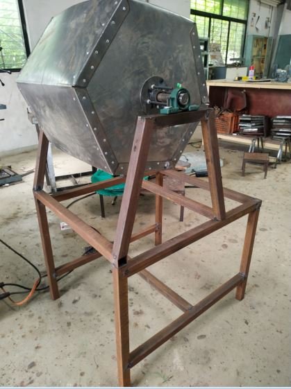
- Frame structure
The structure is designed for 120 liter hexagonal tumbler considering drive system, operational feasibility, structural strength and stability.
- Material of construction
- Frame – Square tube 40 mm*40 mm*2 mm thickness
- L angle – Pedestal bearing mounting
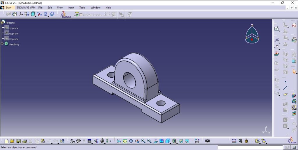
- Drive system components
Current system is motorised with 0.5 hp AC induction motor with RPM of 1450. To reduce RPM and increase torque drive system is designed with reduction gera box and chain-sprocket arrangements. Motor as prime mover delivers transmission to reduction gearbox of ratio 1:40 which is coupled with motor output shaft. The transmisssion then drives drum assembly by chain and sprocket with 1:3 RPM reduction ratio. Driven sprocket of the drive system is coupled to drum side flange by drive plate.
Drum is mounted on shaft which is coupled to pedestal bearing for roatry joint and frame mounting.
Following are the components of drive system.
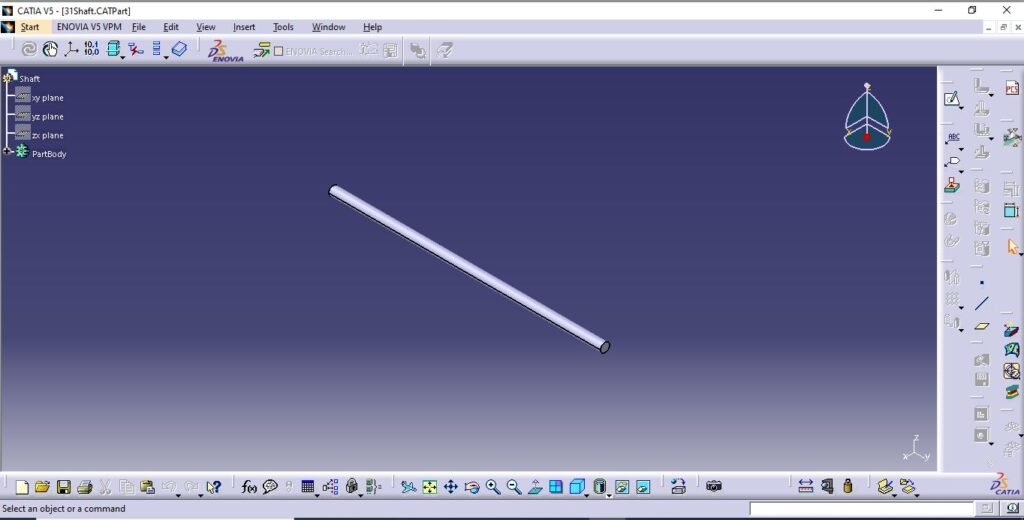
- Shaft and pedestal bearing
- Pedestal bearing standard code from bearing catelogue is P 204.
- Shaft material is EN8 unalloyed medium carbon steel.
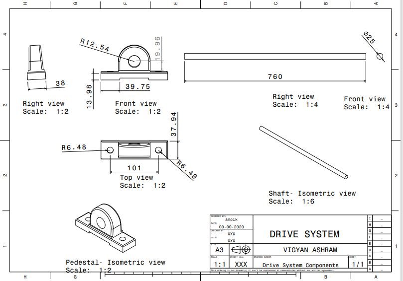
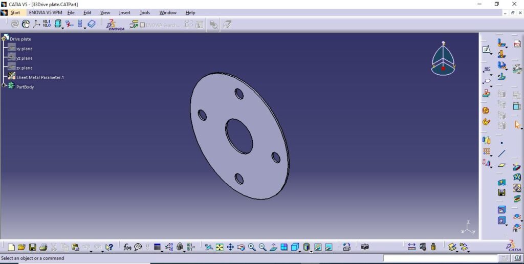
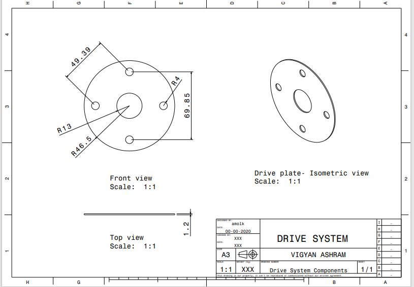
2. Drive plate
- Hopper, covers and chain guard
This components are designed with considering drive system covering and safety requirements, waste and culture mix collection pan, etc.
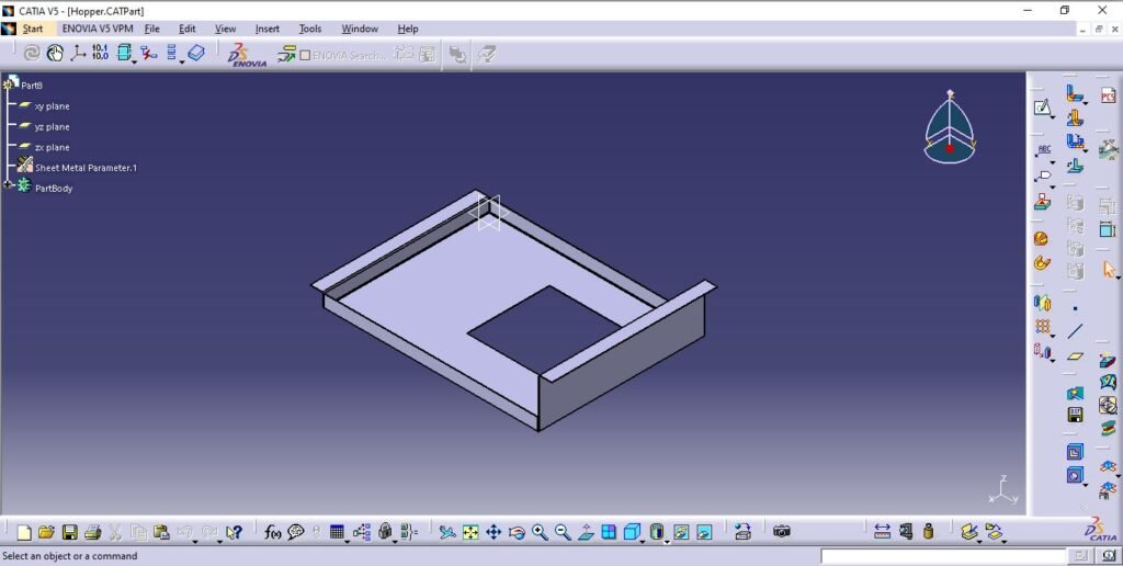
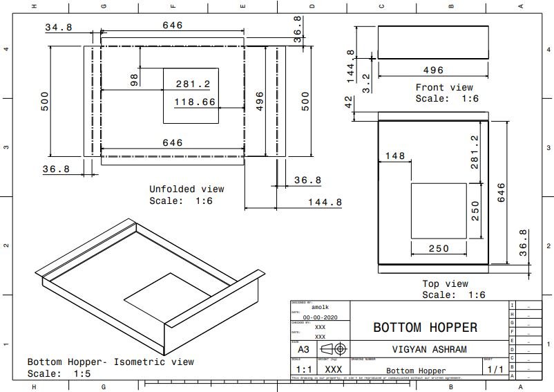
- Bottom hopper
This is designed for collection of mix under the tumbler.
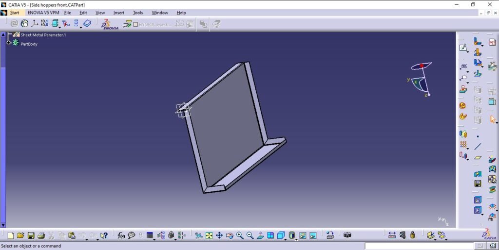
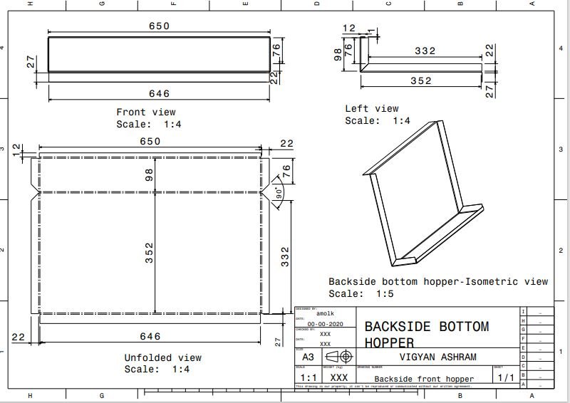
2. Back side bottom hopper
This is designed for mounting on back side of the main bottom hopper.
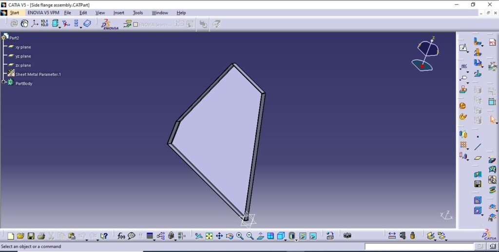
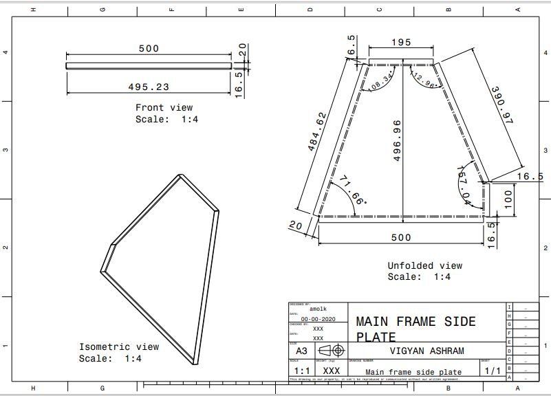
3. Main frame side plates
This side plates are designed to mount in the upper side gap of the main frame to avoid falling of mix outside the machine bottom hoppers during unloading.
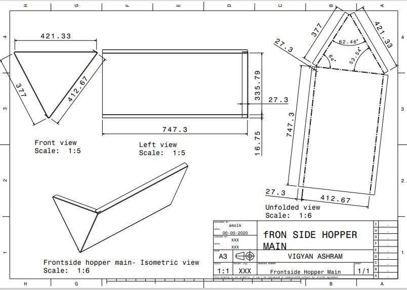
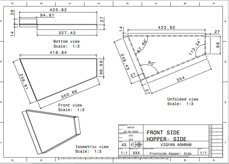
4. Front side hopper main
To avoid falling of mix outside the frame during unloading this hopper is designed.

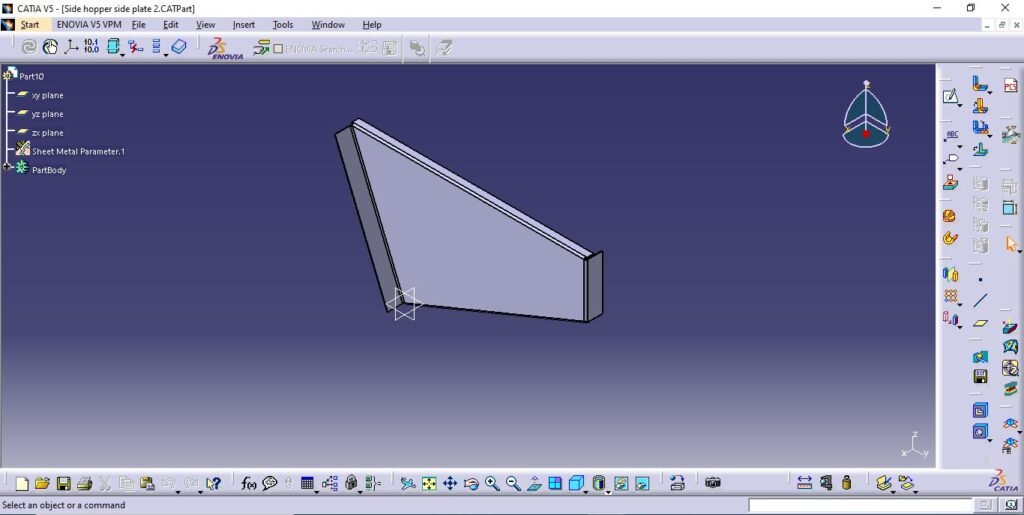
5. Front side hopper side
This is is the side surafce covering part to the main hopper.
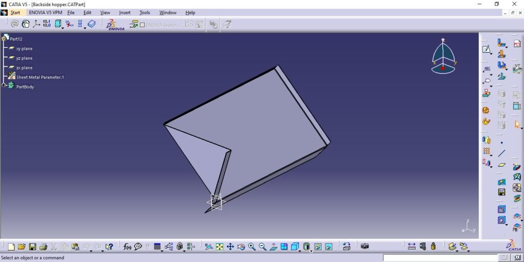
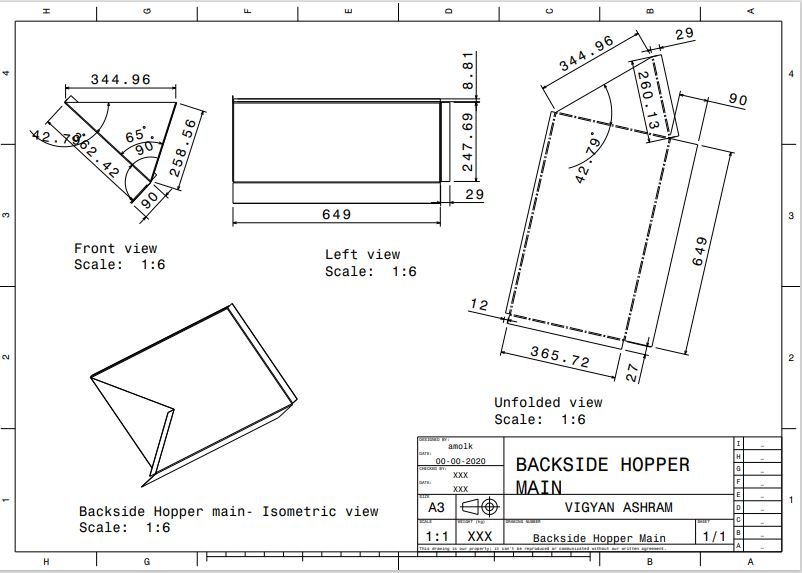
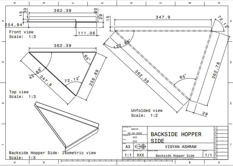
6. Back side hopper main
This is is the side surafce covering part to the main hopper on back side.
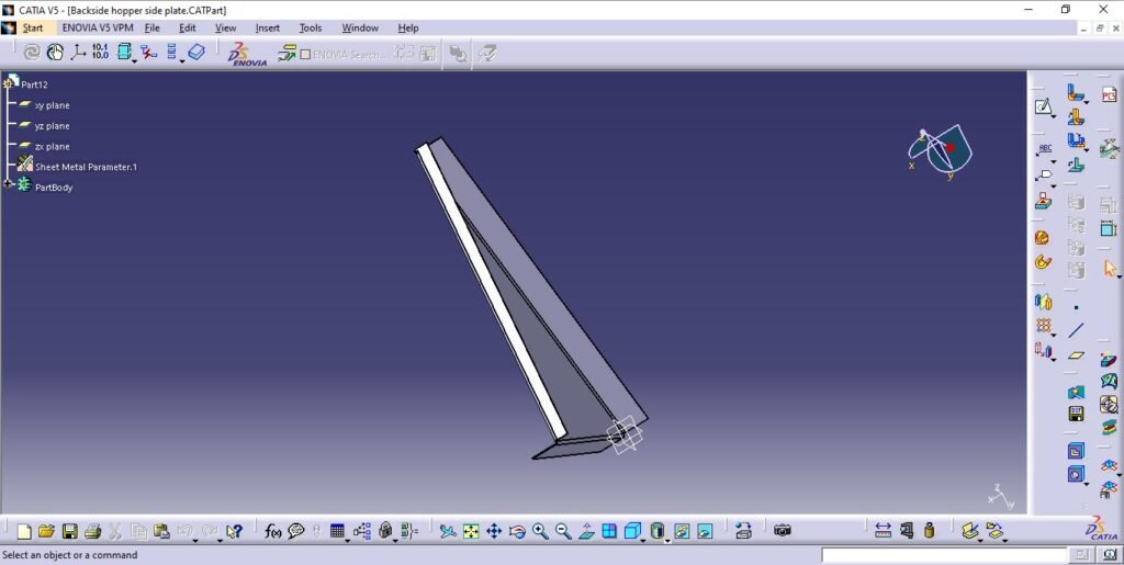
7. Back side hopper side
This is is the side surafce covering part of the back side main hopper.
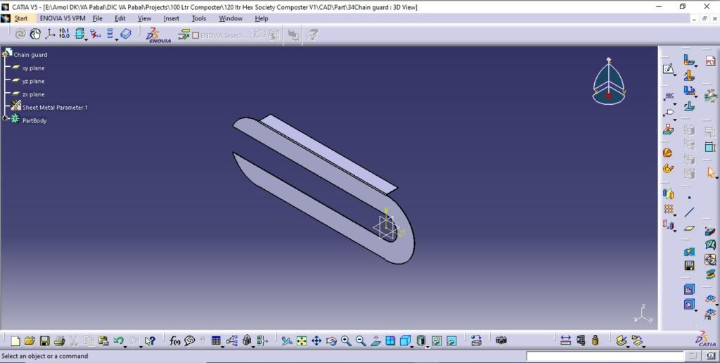
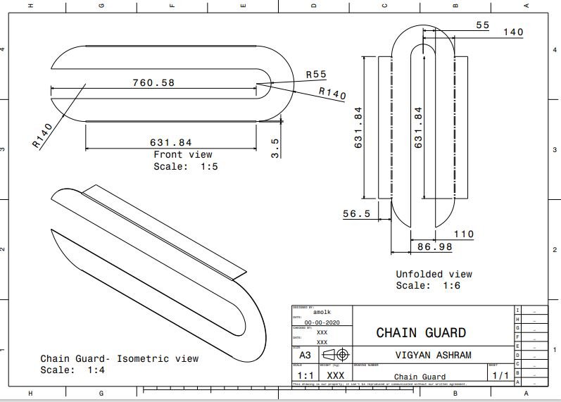
8. Chain guard
Chain guard is the safety cover for chain and sprocket drive assembly.
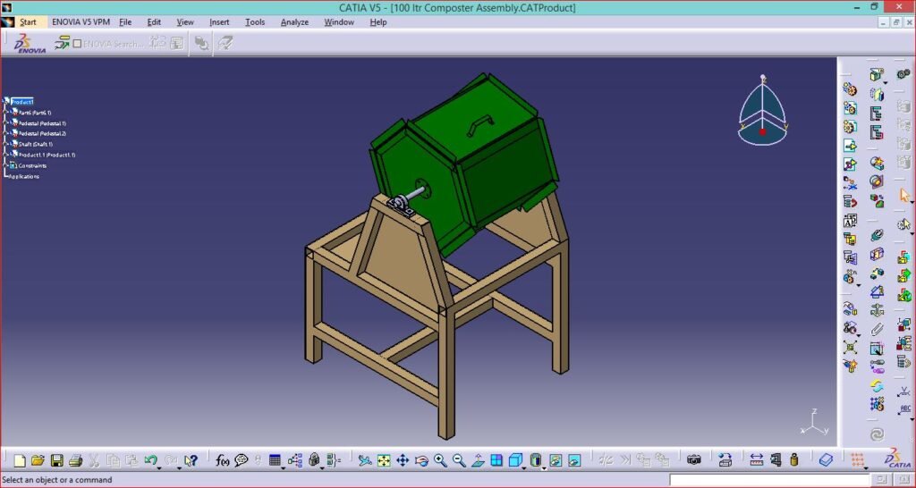
Final Assembly (CAD model)
Manufacturing
Manufacturing process includes sheet cuttinh using CNC plasma cutting machine as per design details. Sheet metal joining done by rivetting with the use of stainless steel rivets to avoid corrrosion and breakdown.
The frame structure is manufactured using arc welding for joining operations.
For drive system parts lathe and vertical milling machines used for opertions such as turning and key way.
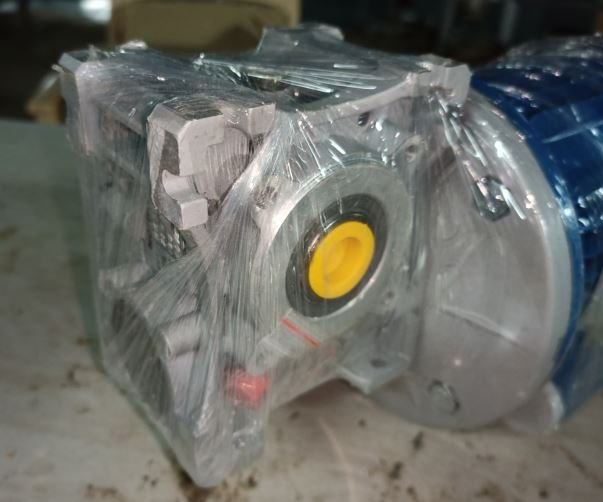
Motor details
Manufacturer Specifications– TEFT, Squirrel-Cage Induction Worm Reduction Geared Motor 0.5 HP, 440 V ~AC, 3 Ph. 50 Hz
- Motor type- AC induction
- Power- Single phase 0.5 HP
- Speed- 1400 RPM
- Manufacturer- MOTHER Motors

Gearbox (Flange mounted with motor)
- Reduction ratio- 40:01
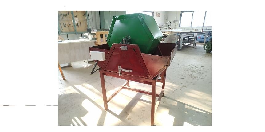
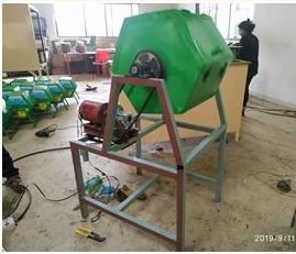
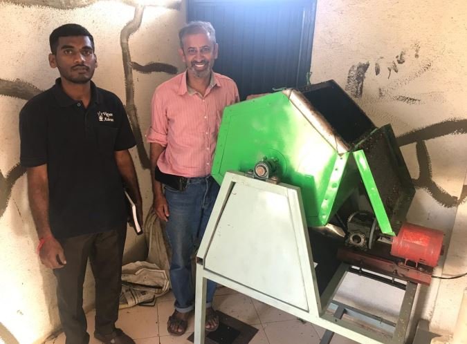
Completely developed Society Composter
Bill of Material
| Sr. No. | Description | Material/Details | No. of Units | Material Quantity | Vendor |
| 1 | Drum Assembly | MS CRCA sheet 1.2 mm thick | 1 | 20 Sq. feet | Samarth Sales Corpo. Pabal |
| 2 | Frame structure | MS square tube 40 mm*40 mm*2 mm thick | 1 | 40 feet | Samarth Sales Corpo. Pabal |
| 3 | Frame structure top | MS L angle 40 mm* 40 mm* 2 mm thick | 2 | 2 feet | Samarth Sales Corpo. Pabal |
| 4 | Shaft | EN 8 25 mm diameter | 1 | 3 feet | Pallavi steel Bhosari |
| 5 | Pedestal bearing | UCP 204 | 2 | 2 | MIDC Bhosari |
| 6 | Drive bush | MS seamless pipe ID 25 mm* 2 mm thick | 4 | 1 feet | Pallavi steel Bhosari |
| 7 | Drive plates | MS CRCA sheet 2 mm thick | 6 | 2 sq. feet | Samarth Sales Corpo. Pabal |
| 8 | Chain and sprocket | Bigger sprocket 42 teeth, small sprocket 13 teeth | 1 | – | Local two wheeler auto. garage |
| 9 | FRP coating inside drum | Glass fibres sheet | 1 | 20 sq. feet | – |
| 10 | Motor with flange mount gearbox | Single phase 0.5 HP AC induction motor 1400 RPM, gearbox 40:01 ratio | 1 | 1 | Mother motors (Mica sales) |
| 11 | Hoppers and covers | MS CRCA sheet 1.2 mm thick | – | 30 sq. feet | Samarth Sales Corpo. Pabal |
| 12 | Electronics | Reverse- forward switch | 1 | 1 | – |
| 13 | Door lock | – | 2 | 2 | – |
| 14 | Door hinges | – | 3 | 3 | – |
| 15 | Rivets | Stainless steel M4*1 Inch | – | 100 | – |
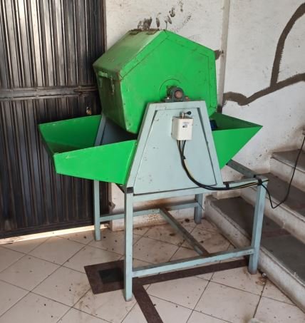
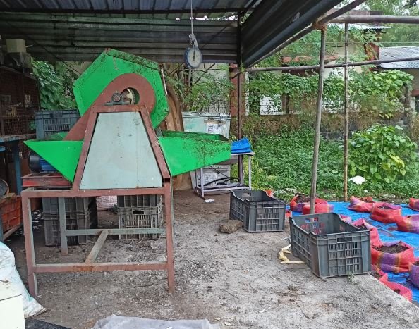
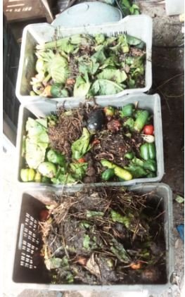
Technology implimentation and field testing
The society composting machine is installed in Kumar Padmalaya housing society, Aundh for field trials and testing.
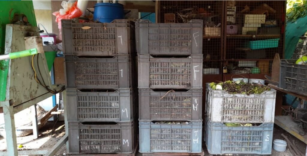
The machine is installed on terrace of building B2. Field trials were conducted for 3 months with daily waste weighing around 15 kg to 20 kg. Akshay Kajarekar was operating the machine and handeling the site and field operations on daily basis.
During field trial and testing at KP Aundh around 1.5 tonne waste processed and converted into compost.
Key Learnings-
- Compost stacking requirement.
- Operator requirements like modifications in machine for ease of loading and unloading.
- Operating switch modifications since it gets actuated by coming in contact of operator moveemnts.
- Forward and reversing requirements.
- Motor and drive system comes in contact of waste.
- Machine overall size is bigger.
This system is also installed at Do It Yourself Lab, Vigyan Ashram Kothrud, Pune campus. Currently this system is in operation from 15th September 2020.
Soham Bodhe and Akshay Kajarekar are operating the system and processed around 0.5 tonne waste into compost.
Link for daily data of Waste processing at Kothrud-
https://docs.google.com/spreadsheets/d/1byeJ2oqZv5Yxdz6AbIqsIhhs-8_CNP53pIf3GvPSolc/edit?usp=sharing
Society Waste Composter (Hexagonal 120 Liter Tumbler) v1.1
Background
With experience from v1.0 field trial and testing need of modifications raised for more convenience in handling and operations of the society composting machine.
This machine is only a motorised waste and microbiological culture mixing tumbler.
From key learning from v1.0 of society waste composter following modifications requirements identofied to work upon;
- Machine dimensions- Machine height needs to be reduce for convenience of operator during loading of waste into tumbler.
- Space for handling or moving mix in collection pan during unloading.
- Space requirement under the bottom hopper for placing collection pan.
- Motor and drive system covering for its protection.
- Drive system safe guards for operator safety.
- Control panel redesigning.
Design Details
By considering the modificatios mentioned above design of 120 liter society composting motorised mixer done. Following are the 3D CAD models and detailed drawings for the same.
There are three main assemblies;
While working on this project we started working with Tata ProEngage team for standerdising design process of Vigyan Ashram projects. Under this activity design library creation started with allotment of project codes.
Society bio waste composter project code is 1001
Each assembly and parts also alloted the identification codes.
- 100101_Stand Assembly
- 100102_Drum Assembly
- 100103_Chain Guard Assembly
- 100101_Stand Assembly
Stand assembly consists of 9 parts listed with brief details as following.
- 10010101_

