Student Name: Akshara Prabhakar Late
Project Introduction
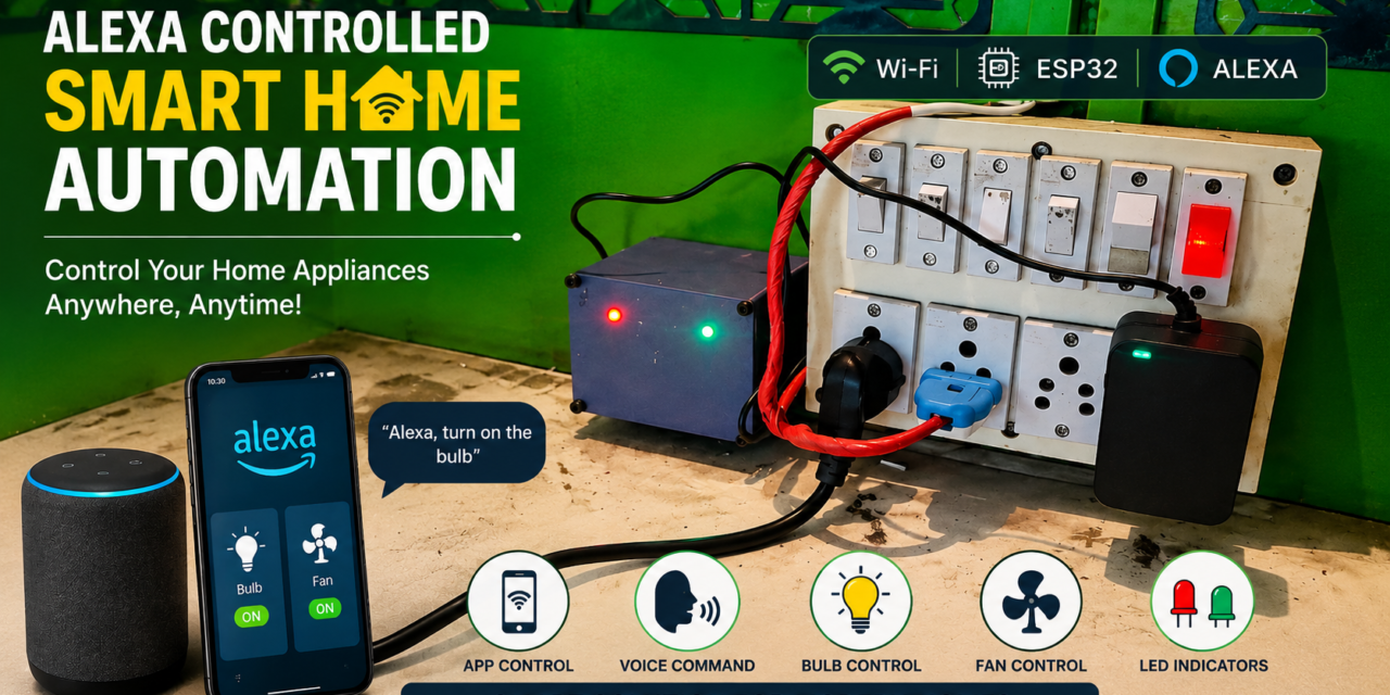
The Wi-Fi Based Smart Home Automation System is an IoT-enabled project developed to make the control of household appliances easier and more convenient. The system uses a 38-pin ESP32 as the main controller along with a 2-channel relay module to control a bulb and a fan.
The system allows the user to switch the bulb and fan ON/OFF wirelessly using a mobile/IoT platform and also supports Amazon Alexa voice control through Sinric Pro. Separate LEDs are provided as visual indicators for the bulb and fan status.
The project was developed step-by-step, starting with individual component testing and breadboard-based circuit development, followed by Wi-Fi, Sinric Pro, and Alexa integration. Finally, the complete system was assembled in a custom 3D-printed enclosure designed using Fusion 360, resulting in a compact and functional smart home automation system.
Problem Statement
In my daily life, I noticed that controlling electrical appliances such as a bulb and a fan requires manually operating the switches. This can be inconvenient when the user is away from the switch or wants to control an appliance remotely. I wanted to develop a simple and practical system that would allow me to control these appliances wirelessly and also through voice commands.
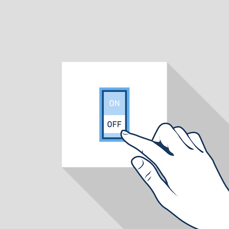
Manual operation of electrical appliances using physical switches.
Proposed Solution
To overcome the problem of manually operating electrical appliances, I decided to develop a wireless home automation system to control them without physically operating the switches. I chose to build this project using an ESP32 so that I could control the appliances remotely, allowing me to operate a bulb and a fan without physically operating their switches.
I wanted to build a simple smart home automation system that could control electrical appliances without depending only on a physical switch. My main idea was to use an ESP32 because it provides built-in Wi-Fi connectivity and is suitable for IoT projects.
I planned to control two appliances, a bulb and a fan, using a relay module. I also wanted to add voice control using Amazon Alexa and provide LED indicators to show the status of each appliance.Before starting the actual hardware work, I planned the main components, connections and overall working of the system.
Working Principle
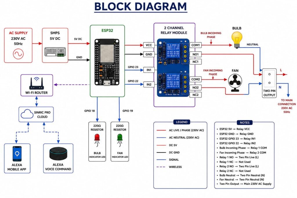
The Smart Home Automation System works by using the ESP32 as the main controller. The ESP32 connects to Wi-Fi and communicates with Sinric Pro. When I give a command through the mobile application or Amazon Alexa, the command is sent to the ESP32 through the internet.
The ESP32 then controls the corresponding relay according to the received command. One relay is used to control the bulb and the other relay is used to control the fan. The respective LED indicator also changes according to the appliance status.
Block Diagram
Project Development – Step by Step
After finalizing the idea of a Wi-Fi based Smart Home Automation System, I started developing the project step by step.
The complete development process I carried out in the following stages:
Research → Component Collection → Components Testing→ Breadboard Circuit Development → Sinric Pro Configuration → Arduino Ide Setup→ Amazon Alexa Integration → Power Supply and Voice Control Testing→ Fusion 360 Casing Design → 3D Printing → Soldering→ Final Assembly → Complete System Testing Result
Step 1– Research
I started the project by researching how a Wi-Fi based home automation system could be developed for controlling household appliances. I explored different microcontrollers, relay modules, IoT platforms, and voice-control options suitable for the project.
After considering the project requirements, I selected the 38-pin ESP32 as the main controller because it provides Wi-Fi connectivity and is suitable for controlling the bulb and fan through relays. I also planned to use Sinric Pro and Amazon Alexa for wireless and voice-based control, along with LEDs for appliance status indication.
Step 2 – Components Collection
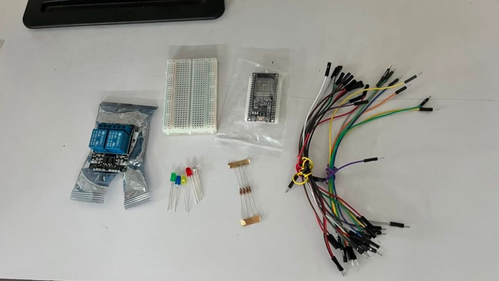
Once the project requirements were finalized, I gathered the components needed to build and test the smart home automation system. The components were selected according to the circuit design and the functions planned for the project.
Hardware Components
- ESP32 38-pin Wi-Fi + Bluetooth Development Board — 1
- 2-Channel 5V Relay Module — 1
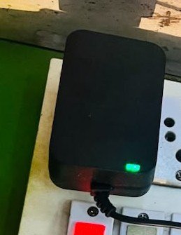
- 5V SMPS — 1
- SMPS Female Connector— 1
- LED Indicators — 2
- 220Ω Resistors — 2
- Breadboard — 1
- Jumper Wires — As required
- Connectors — As required
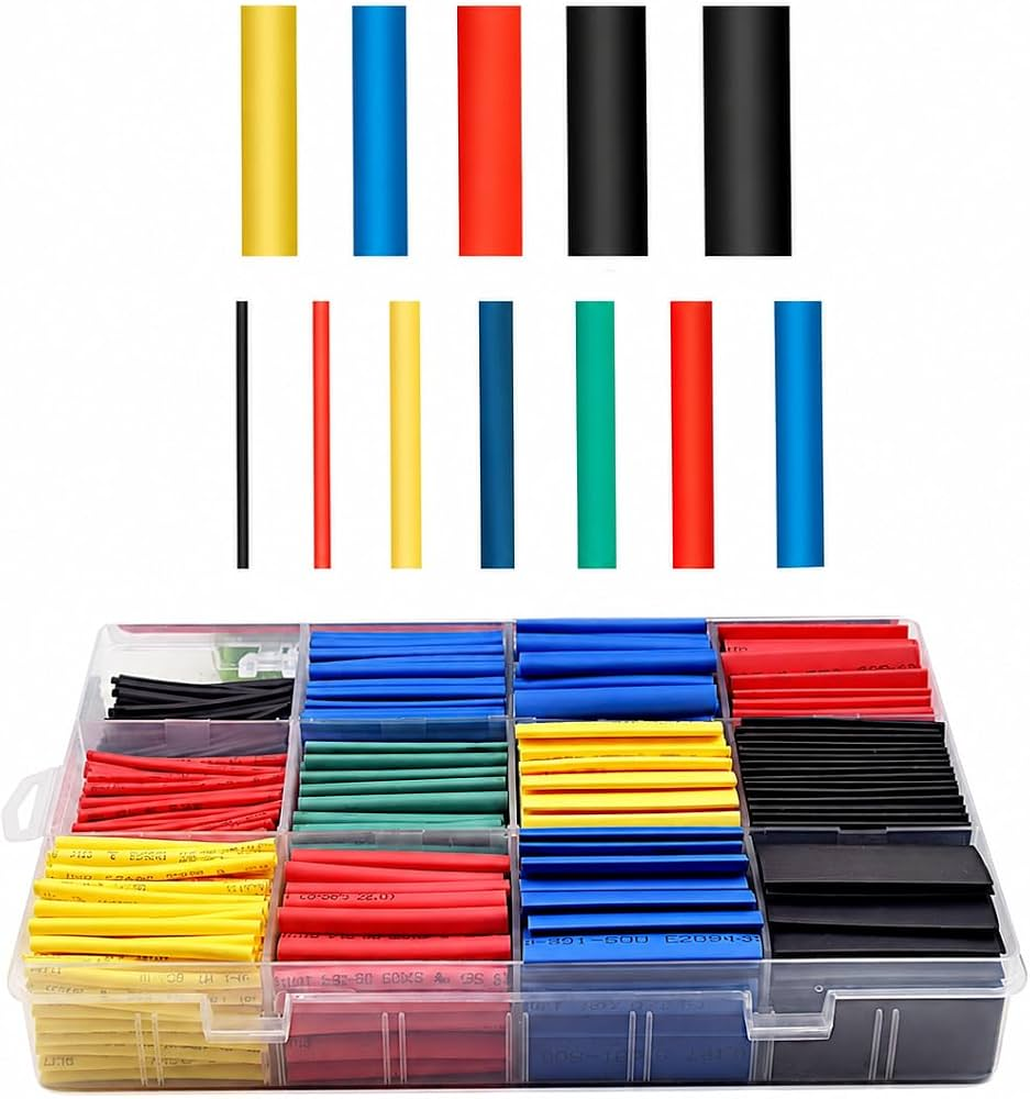
- Heat-Shrink Sleeves — As required
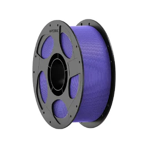
- 3D Printing PLA Filament — As Required
Software / Platforms
- Arduino IDE
- Sinric Pro
- Amazon Alexa
Step 3 – Components Testing
After collecting all the components,I first tested the components individually and then combined them into the complete circuit. This helped me verify the relay operation, LED indication, and ESP32 control before proceeding with the final hardware assembly.
Relay Test Code
#define RELAY1 23
#define RELAY2 22

void setup() {
  pinMode(RELAY1, OUTPUT);
  pinMode(RELAY2, OUTPUT);

  digitalWrite(RELAY1, HIGH);
  digitalWrite(RELAY2, HIGH);
}

void loop() {
  digitalWrite(RELAY1, LOW);   // Relay 1 ON
  delay(2000);

  digitalWrite(RELAY1, HIGH);  // Relay 1 OFF
  delay(2000);

  digitalWrite(RELAY2, LOW);   // Relay 2 ON
  delay(2000);

  digitalWrite(RELAY2, HIGH);  // Relay 2 OFF
  delay(2000);
}
LED Status With Relay Code
#define RELAY1 23
#define RELAY2 22

#define LED1 18
#define LED2 19

void setup() {
  pinMode(RELAY1, OUTPUT);
  pinMode(RELAY2, OUTPUT);

  pinMode(LED1, OUTPUT);
  pinMode(LED2, OUTPUT);

  digitalWrite(RELAY1, HIGH);
  digitalWrite(RELAY2, HIGH);
  digitalWrite(LED1, LOW);
  digitalWrite(LED2, LOW);
}

void loop() {

  // Bulb ON
  digitalWrite(RELAY1, LOW);
  digitalWrite(LED1, HIGH);
  delay(2000);

  // Bulb OFF
  digitalWrite(RELAY1, HIGH);
  digitalWrite(LED1, LOW);
  delay(2000);

  // Fan ON
  digitalWrite(RELAY2, LOW);
  digitalWrite(LED2, HIGH);
  delay(2000);

  // Fan OFF
  digitalWrite(RELAY2, HIGH);
  digitalWrite(LED2, LOW);
  delay(2000);
}
Step 4 – Sinric Pro Configuration

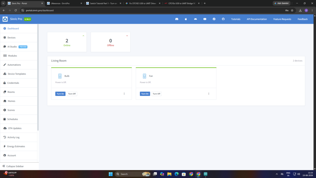
Sinric Pro is an IoT platform that allows hardware devices such as the ESP32 to connect to the internet and communicate with smart-home applications and services. It acts as a communication link between my ESP32 and the connected smart-home controls.
In my project, I used Sinric Pro to create and manage separate Bulb and Fan devices. It allows the commands given through the platform or Amazon Alexa to reach my ESP32, which then controls the corresponding relay and appliance.
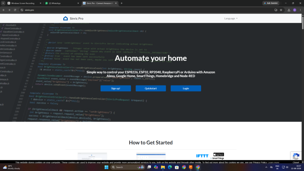
1.Sinric Pro Platform – Opened the Sinric Pro platform to begin the IoT setup.
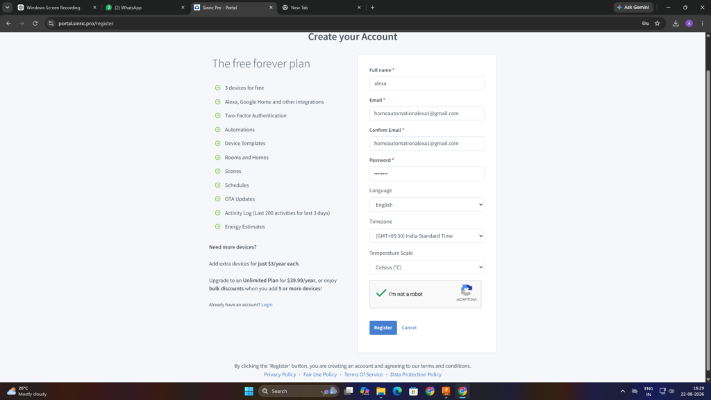
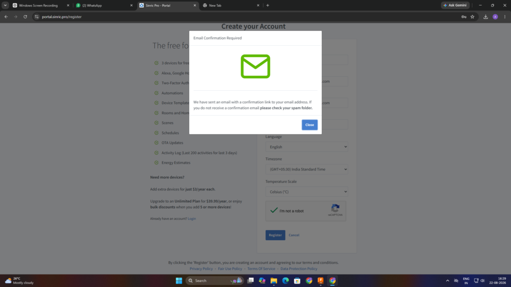
2.Create Account – I Created a new Sinric Pro account using my email address.
3.Email Confirmation – Confirmed the account through the email verification link.
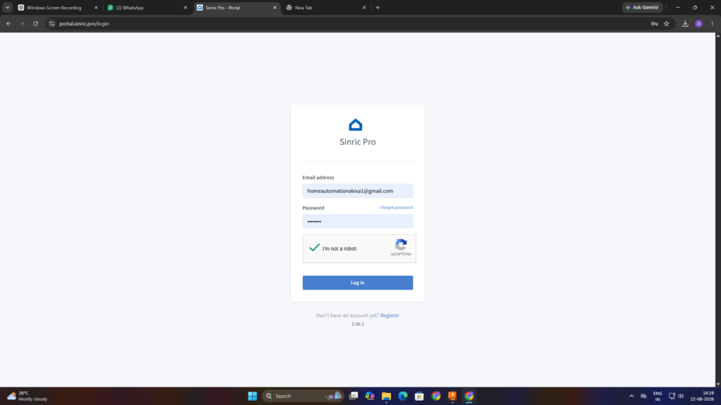
4.Login – Logged in to the Sinric Pro platform using the registered account.
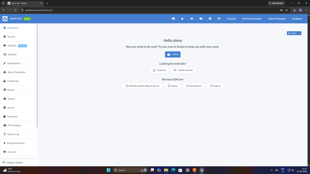
5.Sinric Pro Dashboard – Accessed the Sinric Pro dashboard to configure the smart home devices.
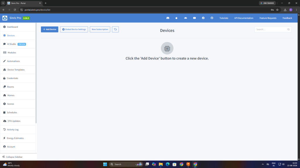
6. Add Device – Selected the option to add a new device to the project
7. Create Bulb Device – Created a new device for controlling the bulb,Entered the required device name, type and description for the bulb.
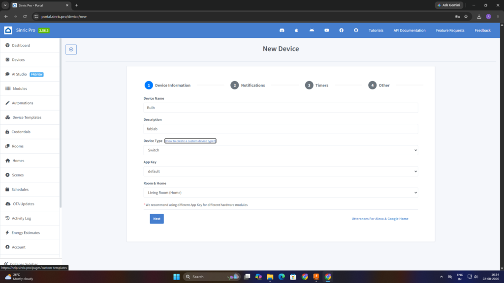
8. Bulb Credentials – Generated and noted the Device ID, App Key, and App Secret for the bulb setup.
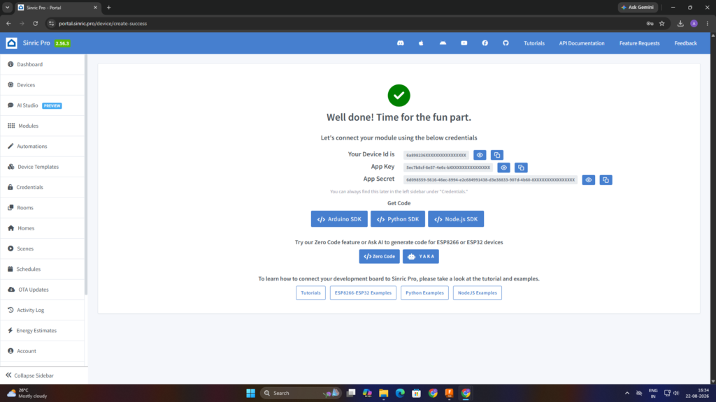
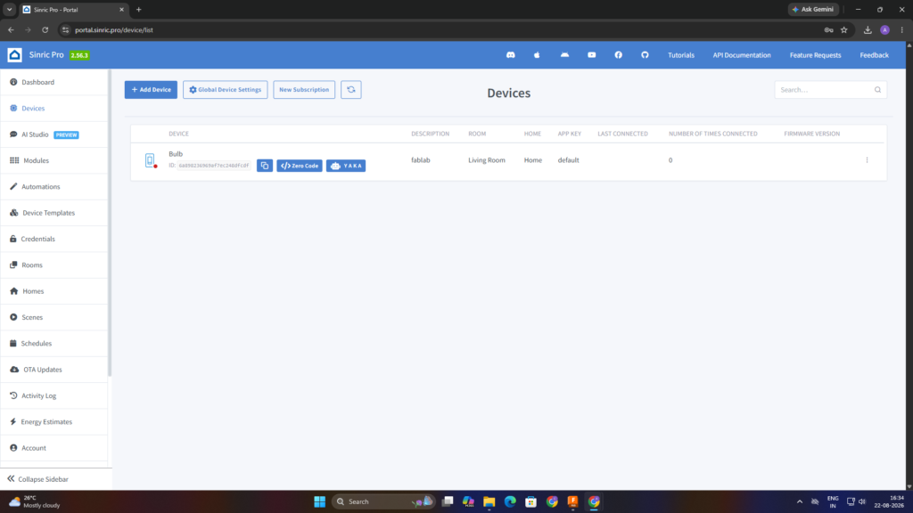
9. Bulb Device Created – Successfully added the bulb device to the Sinric Pro platform.
10.Create Fan Device – Created a separate new device for controlling the fan,Entered the required device name,type and description for the fan.
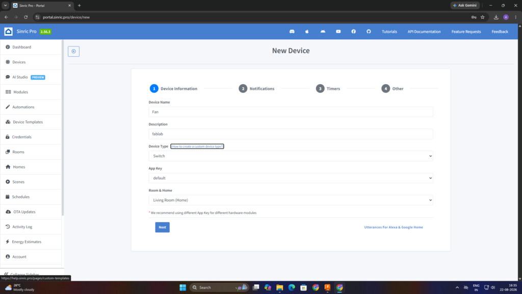
11. Fan Credentials – Generated and noted the Device ID, App Key, and App Secret for the fan setup,Successfully added the fan device to the Sinric Pro platform.
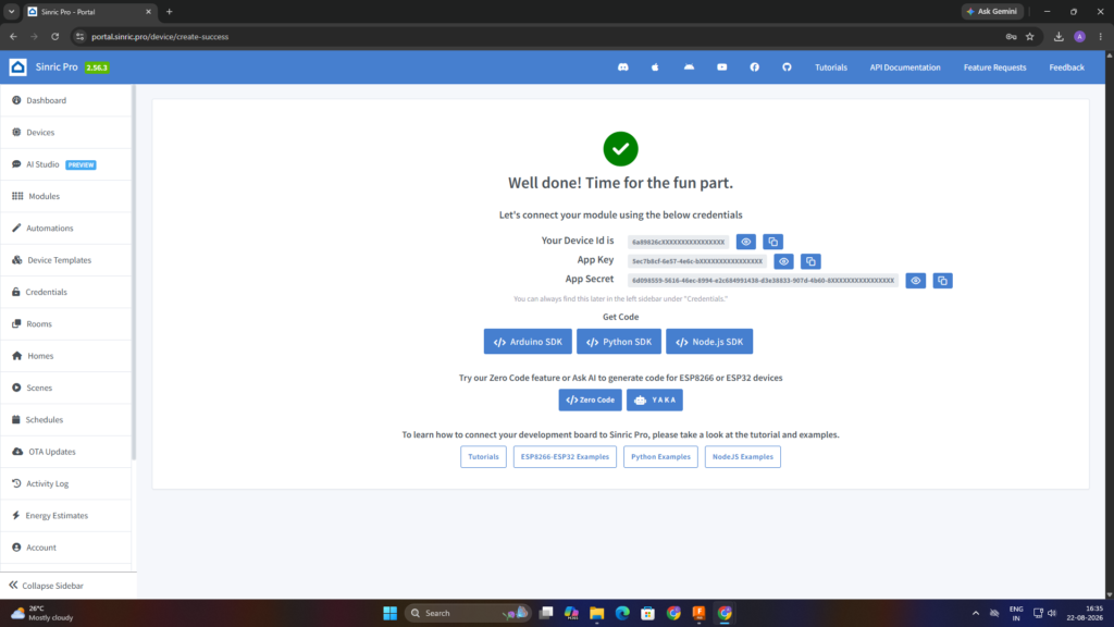
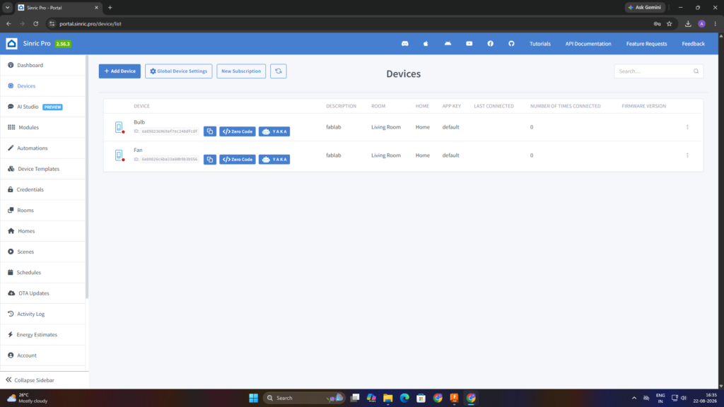
12. Device Interface – Verified that both the Bulb and Fan devices were available on the Sinric Pro dashboard.I added two separate devices, Bulb and Fan, to my Sinric Pro account. I completed the device creation process for the first device by entering the required device details and obtaining the Device ID, App Key, and App Secret. I then followed the same configuration process to add the second device, changing only the device-specific information. The remaining settings and configuration steps were kept the same for both devices.
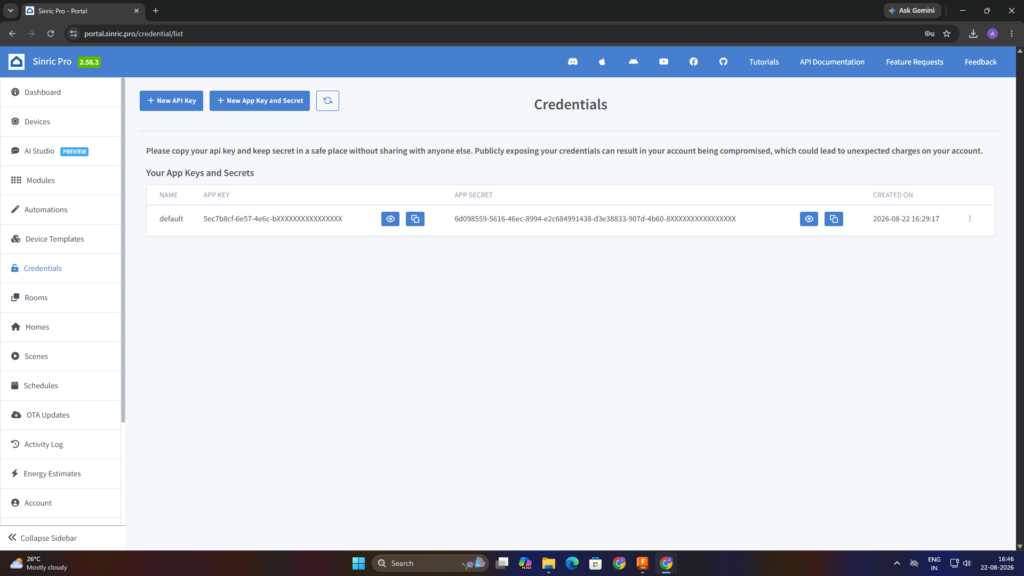
13. Copy Credentials – Copied the required Device ID, App Key, and App Secret from the Sinric Pro credentials section for use in the ESP32 program.
Step 5 – Breadboard Circuit Development
I started developing and testing the circuit on a breadboard. I connected the ESP32, 2-channel relay module, indicator LEDs, and other required components according to the planned connections.
ESP32 Pin Connections
| ESP32 Pin | Connected Component | Purpose |
|---|---|---|
| GPIO 23 | Relay IN1 | Bulb control |
| GPIO 22 | Relay IN2 | Fan control |
| GPIO 18 | 220Ω Resistor-Bulb Indicator LED | Bulb status indication |
| GPIO 19 | 220Ω Resistor-Fan Indicator LED | Fan status indication |
| 5V / VIN | 5V Supply | Power supply |
| GND | Common Ground | Ground connection |
Relay Connections
- Relay IN1 → GPIO 23 → Bulb
- Relay IN2 → GPIO 22 → Fan
- Relay COM1 → Bulb incoming phase
- Relay COM2 → Fan incoming phase
- Relay NO1 → Bulb output
- Relay NO2 → Fan output
LED Connections
- ESP32 GPIO 18 → 220Ω Resistor → Bulb Indicator LED
- ESP32 GPIO 19 → 220Ω Resistor → Fan Indicator LED
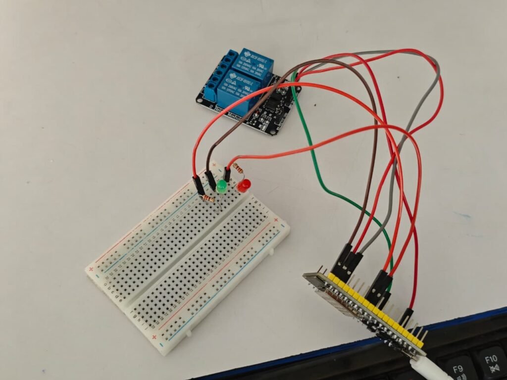
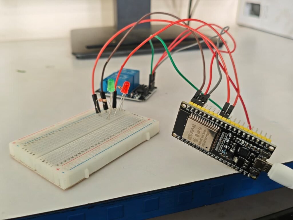
This breadboard testing stage helped me identify and correct connection or programming issues before moving towards the final assembly and enclosure.
Step 6 – Arduino Ide Setup Programming
Arduino IDE (Integrated Development Environment) is a software platform used to write, compile, and upload programs to microcontroller boards. I used Arduino IDE to develop the program for my 38-pin ESP32 and upload it through the USB connection.
For my project, I used Arduino IDE to program the relay control, LED indication, Wi-Fi connection, and Sinric Pro integration. It also allowed me to test and modify the program during the development process before finalizing the complete system.
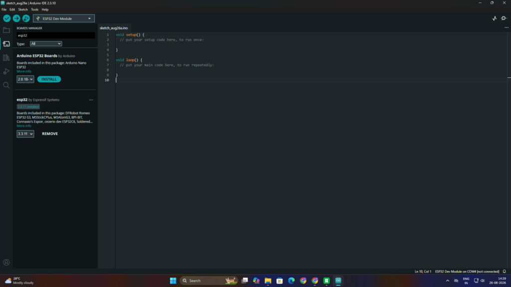
1. Install ESP32 Board Package – I opened the Arduino IDE and installed the required ESP32 board package through the Board Manager so that I could program my ESP32 development board.
2. Install Sinric Pro Library– I installed the Sinric Pro library in Arduino IDE to enable communication between my ESP32 and the Sinric Pro platform.
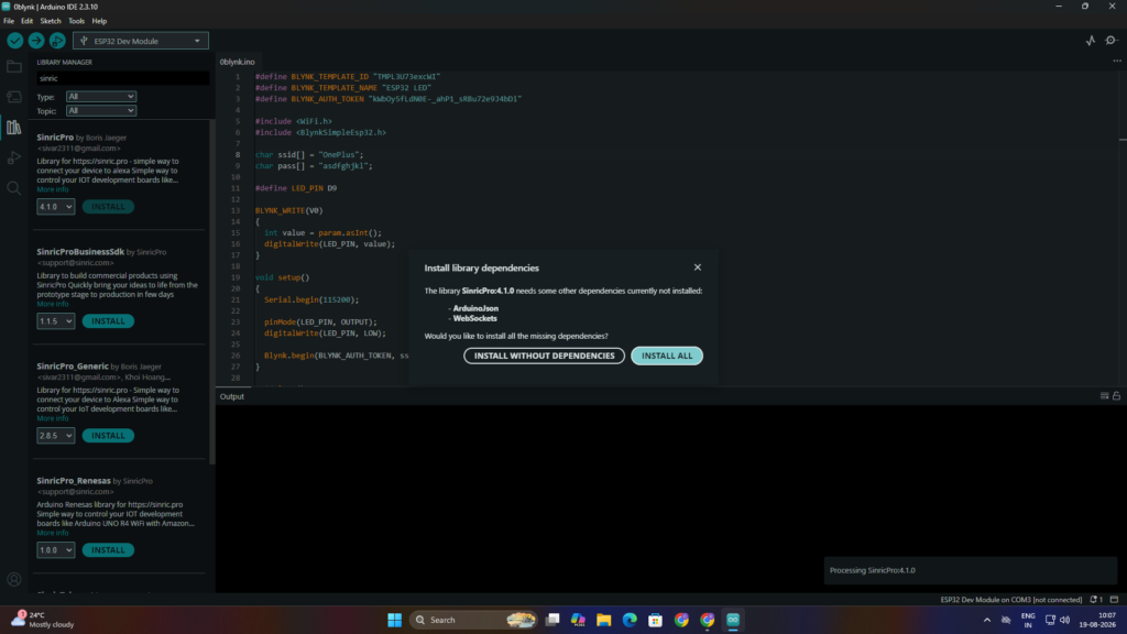
3. Prepare the Code – I prepared the ESP32 program and added the required code for Wi-Fi, relay control, LED indication, and Sinric Pro communication.
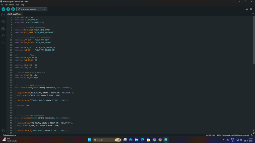
4. Add Sinric Pro Details – I added the Bulb Device ID, Fan Device ID, App Key, and App Secret obtained from my Sinric Pro account into the ESP32 program.
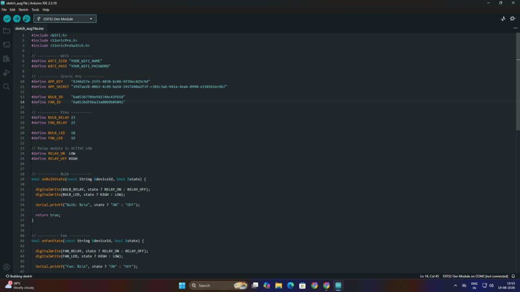
5. Add Wi-Fi Details– I entered my Wi-Fi network name and password in the program so that the ESP32 could connect to the internet.I connected the ESP32 to my computer using the USB cable and selected the appropriate ESP32 board in Arduino IDE.I clicked the Upload button in Arduino IDE to upload the program to the ESP32.
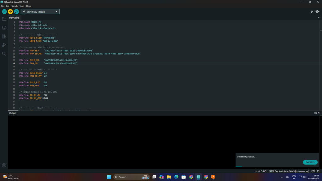
6. Press BOOT Button– When the Arduino IDE displayed “Connecting…”, I pressed and held the BOOT button on the ESP32 until the upload process started.Once the programming process started, I released the BOOT button and allowed the code to finish uploading.After the code was successfully uploaded, the ESP32 was ready to connect with Wi-Fi and Sinric Pro and control the bulb and fan.
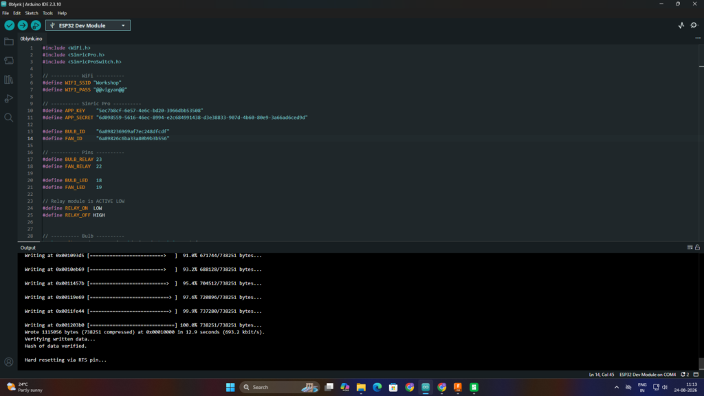
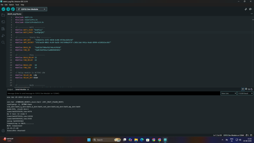
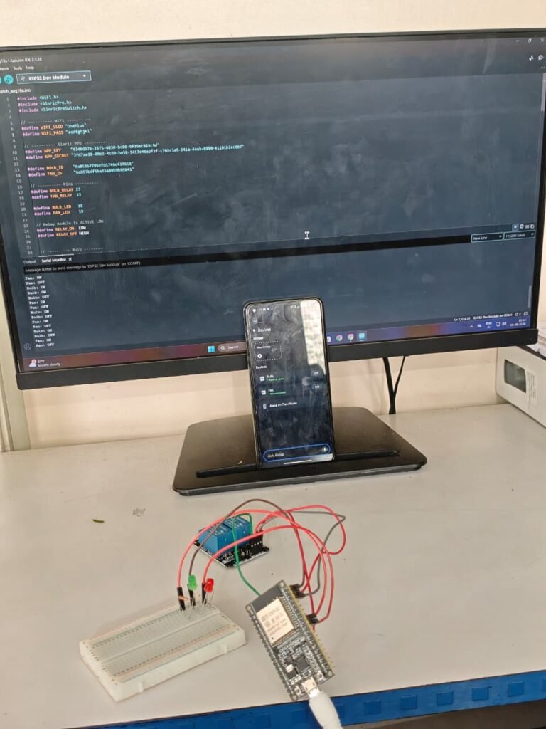
7.Verify Wi-Fi Connection– After the code was successfully uploaded, I opened the Serial Monitor in Arduino IDE to check the ESP32 status. The Serial Monitor displayed the Wi-Fi connection status, confirming that the ESP32 was successfully connected to the configured Wi-Fi network.
Sinric pro dashboard:
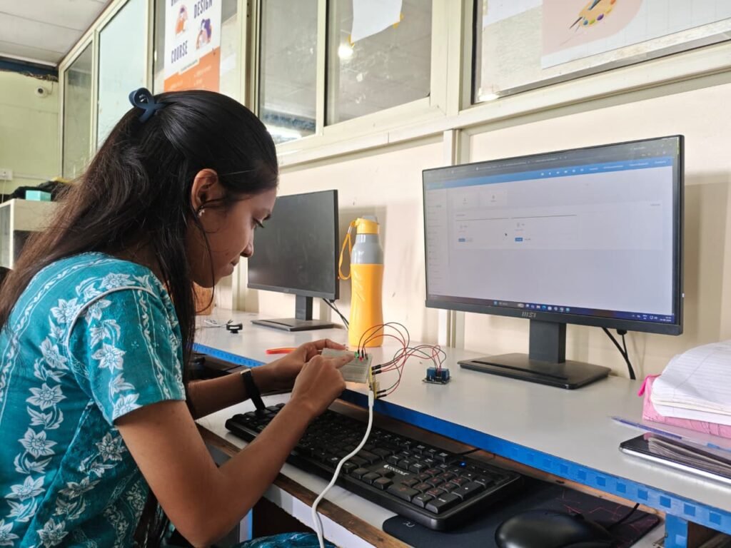
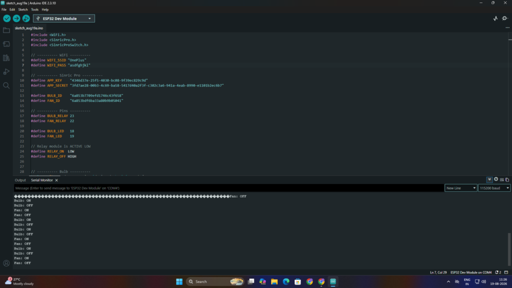
Arduino Ide Showing Bulb & Fan Status:
Final Code:
#include <WiFi.h>
#include <SinricPro.h>
#include <SinricProSwitch.h>

// ---------- WiFi ----------
#define WIFI_SSID "Wifi name"
#define WIFI_PASS "wifi password"

// ---------- Sinric Pro ----------
#define APP_KEY    "APP_KEY"
#define APP_SECRET "APP_SECRET"

#define BULB_ID    "BULB_ID"
#define FAN_ID     "FAN_ID"

// ---------- Pins ----------
#define BULB_RELAY 23
#define FAN_RELAY  22

#define BULB_LED   18
#define FAN_LED    19

// Relay module is ACTIVE LOW
#define RELAY_ON  LOW
#define RELAY_OFF HIGH


// ---------- Bulb ----------
bool onBulbState(const String &deviceId, bool &state) {

  digitalWrite(BULB_RELAY, state ? RELAY_ON : RELAY_OFF);
  digitalWrite(BULB_LED, state ? HIGH : LOW);

  Serial.printf("Bulb: %s\n", state ? "ON" : "OFF");

  return true;
}


// ---------- Fan ----------
bool onFanState(const String &deviceId, bool &state) {

  digitalWrite(FAN_RELAY, state ? RELAY_ON : RELAY_OFF);
  digitalWrite(FAN_LED, state ? HIGH : LOW);

  Serial.printf("Fan: %s\n", state ? "ON" : "OFF");

  return true;
}


// ---------- WiFi ----------
void setupWiFi() {

  Serial.print("Connecting to WiFi");

  WiFi.begin(WIFI_SSID, WIFI_PASS);

  while (WiFi.status() != WL_CONNECTED) {
    delay(500);
    Serial.print(".");
  }

  Serial.println();
  Serial.println("WiFi Connected!");
  Serial.println(WiFi.localIP());
}


// ---------- Sinric Pro ----------
void setupSinricPro() {

  pinMode(BULB_RELAY, OUTPUT);
  pinMode(FAN_RELAY, OUTPUT);

  pinMode(BULB_LED, OUTPUT);
  pinMode(FAN_LED, OUTPUT);

  // Everything OFF at startup
  digitalWrite(BULB_RELAY, RELAY_OFF);
  digitalWrite(FAN_RELAY, RELAY_OFF);

  digitalWrite(BULB_LED, LOW);
  digitalWrite(FAN_LED, LOW);


  SinricProSwitch &bulb = SinricPro[BULB_ID];
  bulb.onPowerState(onBulbState);


  SinricProSwitch &fan = SinricPro[FAN_ID];
  fan.onPowerState(onFanState);


  SinricPro.begin(APP_KEY, APP_SECRET);

  Serial.println("SinricPro Started!");
}


// ---------- Setup ----------
void setup() {

  Serial.begin(115200);

  setupWiFi();
  setupSinricPro();
}


// ---------- Loop ----------
void loop() {

  SinricPro.handle();
}
Step 7- Amazon Alexa Integration
Amazon Alexa is a voice-based smart assistant that allows users to control compatible smart-home devices using voice commands. It can be connected with IoT platforms such as Sinric Pro to provide voice-based appliance control.
In my project, I used the Amazon Alexa mobile application to connect my Sinric Pro account and access the configured Bulb and Fan devices. After connecting them, I was able to control the bulb and fan through the Alexa app and voice commands.
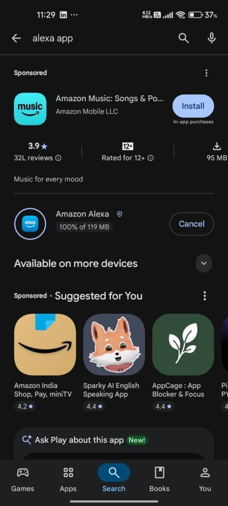
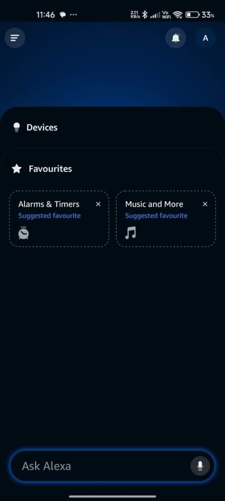
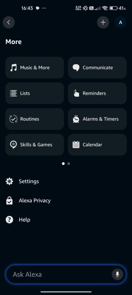
1. Install Amazon Alexa App – After completing the ESP32 programming, I installed the Amazon Alexa mobile application on my smartphone to add voice-based control to my project.I opened the Alexa application and created/logged into my account to start the device integration process.From the More section, I selected the Skills & Games option to search for the required Sinric Pro skill.
2. Search for Sinric Pro– I searched for Sinric Pro in the Skills & Games section of the Alexa application.Enable Sinric Pro SkillI selected the Sinric Pro skill and enabled it using the Enable to Use option.
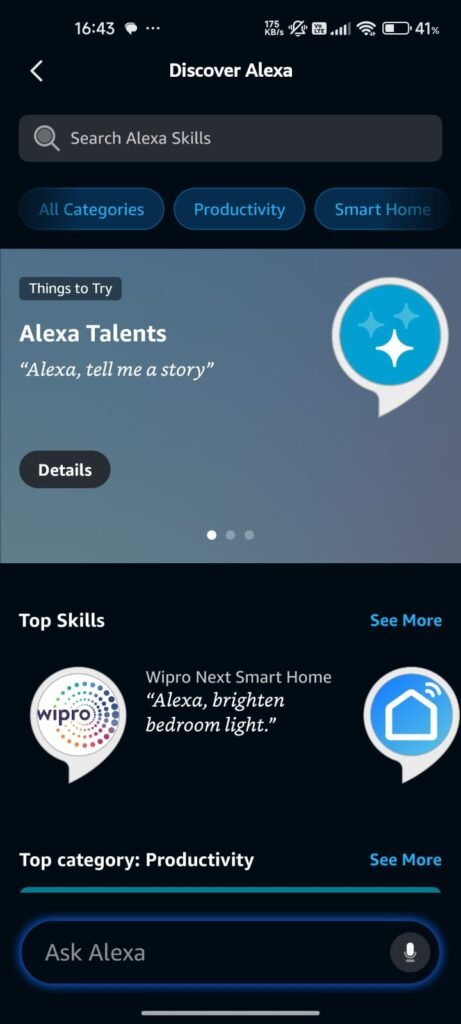
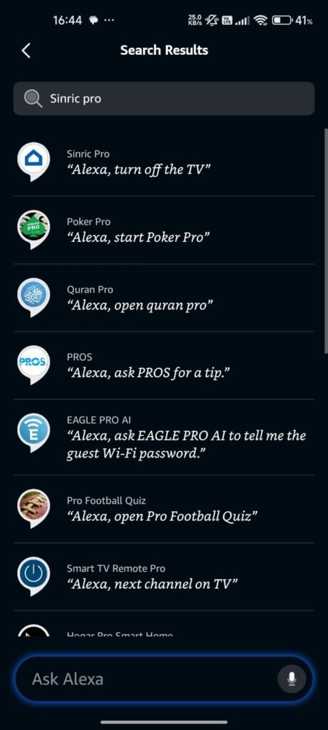
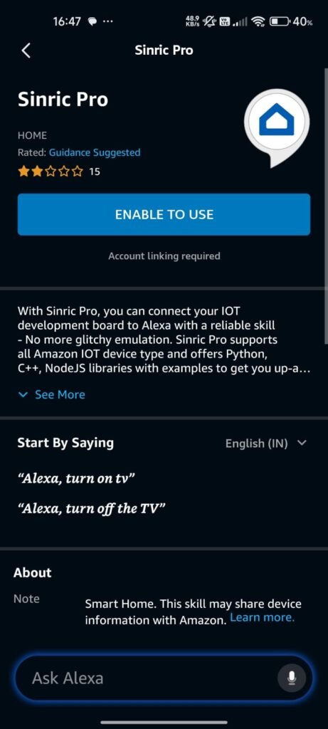
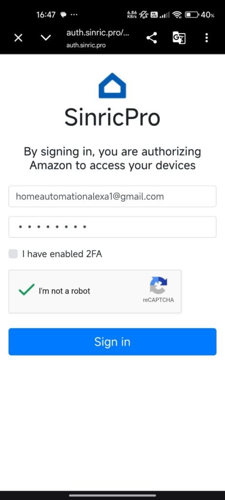
3. Link Sinric Pro Account – I entered the same account details that I had used while creating my Sinric Pro account to link Sinric Pro with Amazon Alexa. After successful account linking, my Sinric Pro devices were connected to the Alexa application, allowing Alexa to access the configured Bulb and Fan devices.
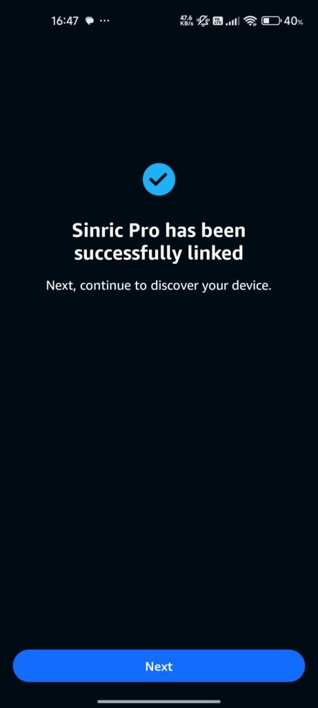
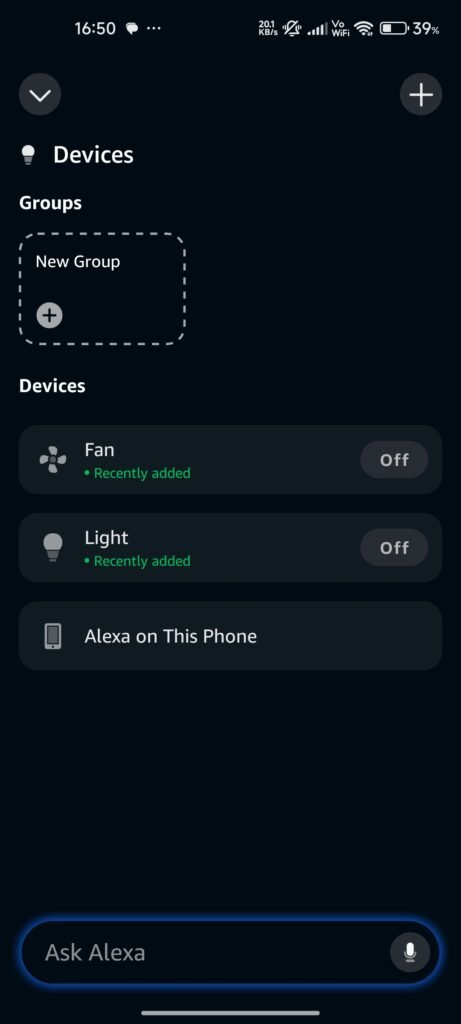
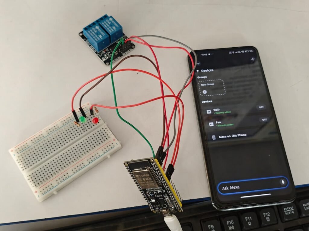
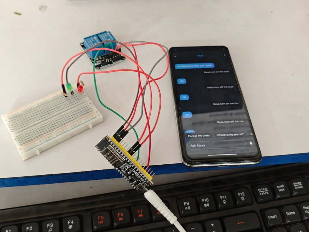
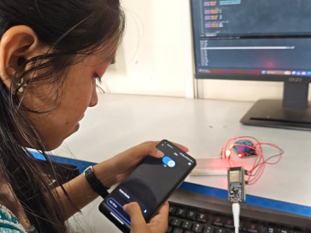
4. Appliance Control – I then tested the devices through the Alexa application by switching the bulb and fan ON and OFF and verified that the corresponding relay and indicator LED responded correctly.
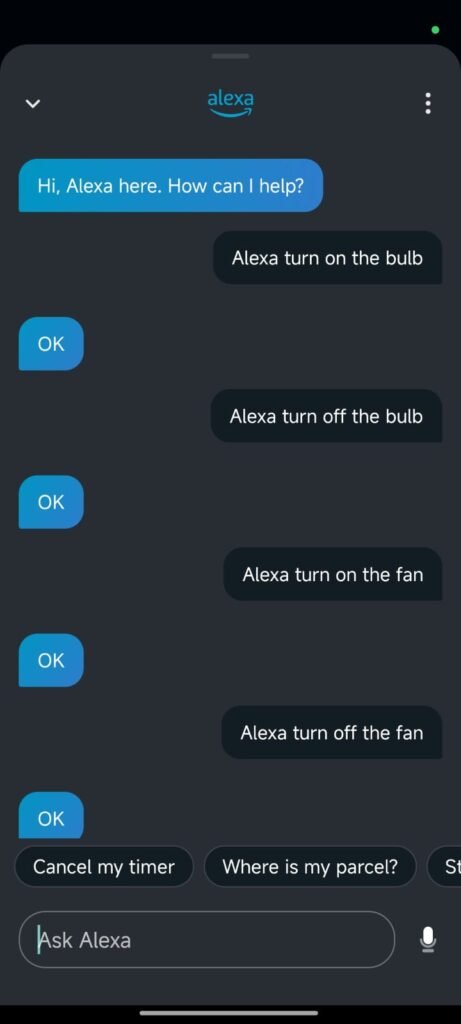
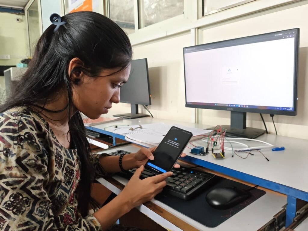
I tested the system in two ways using the Amazon Alexa mobile application. First, I manually used the ON/OFF buttons in the Alexa app to control the bulb and fan. Then, I tested the same appliances by giving voice commands through Alexa and verified that both responded correctly.
Step 8 – Power Supply and Voice Control Testing
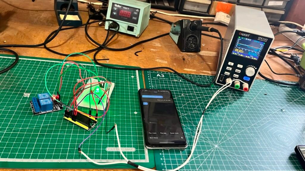
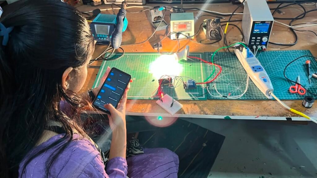
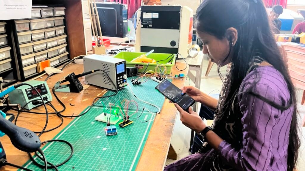
After completing the Sinric Pro and Amazon Alexa integration, I tested the system with the required power supply. I provided a 5V supply to the ESP32 and verified that the controller was operating properly.
I then tested the system using Alexa voice commands to control the bulb and fan. I checked whether the voice commands were correctly received and whether the corresponding relay and indicator LED responded as expected. This testing confirmed that the system was working properly with Wi-Fi, Sinric Pro, and Alexa-based control.
Step 9 – Casing Design
After successfully testing the complete system, I designed a custom enclosure for the project using Fusion 360.
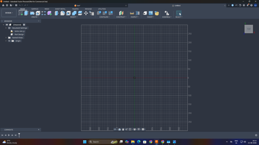
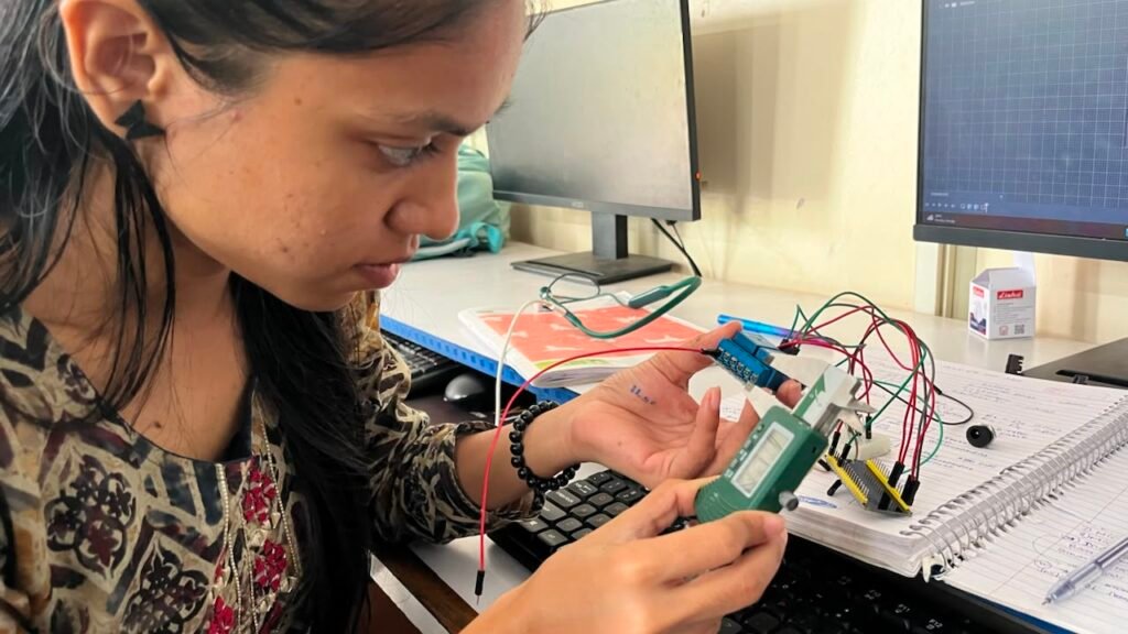
I planned the enclosure according to the size and arrangement of the components so that the final system would be compact, organized, and suitable for 3D printing,I used Vernier Caliper for accurate measurements.
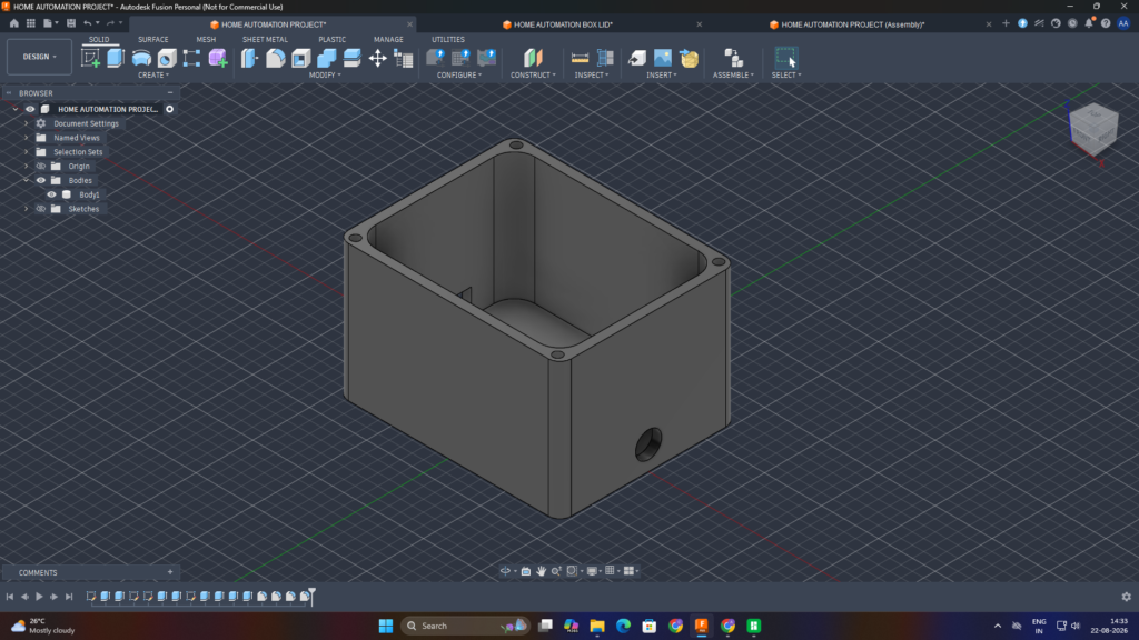
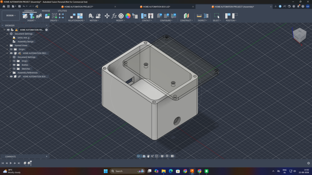
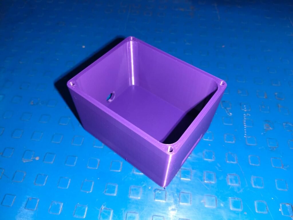
I created a main box structure to house the ESP32, relay module, and other required components, along with a separate lid to cover and protect the internal setup.
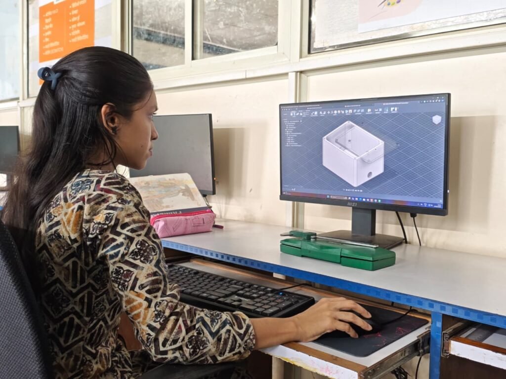
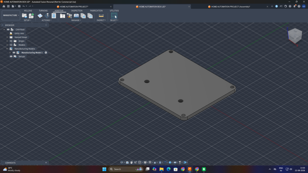
After designing the main box and lid, I added the required openings according to the component arrangement. I created a cut-out for the relay connection pins,circular opening for the adapter/power connection and provided circular cut off at lid for LEDs.These openings were designed to make the external connections accessible while keeping the overall enclosure neat and organized.
Step 10 – 3D Printing
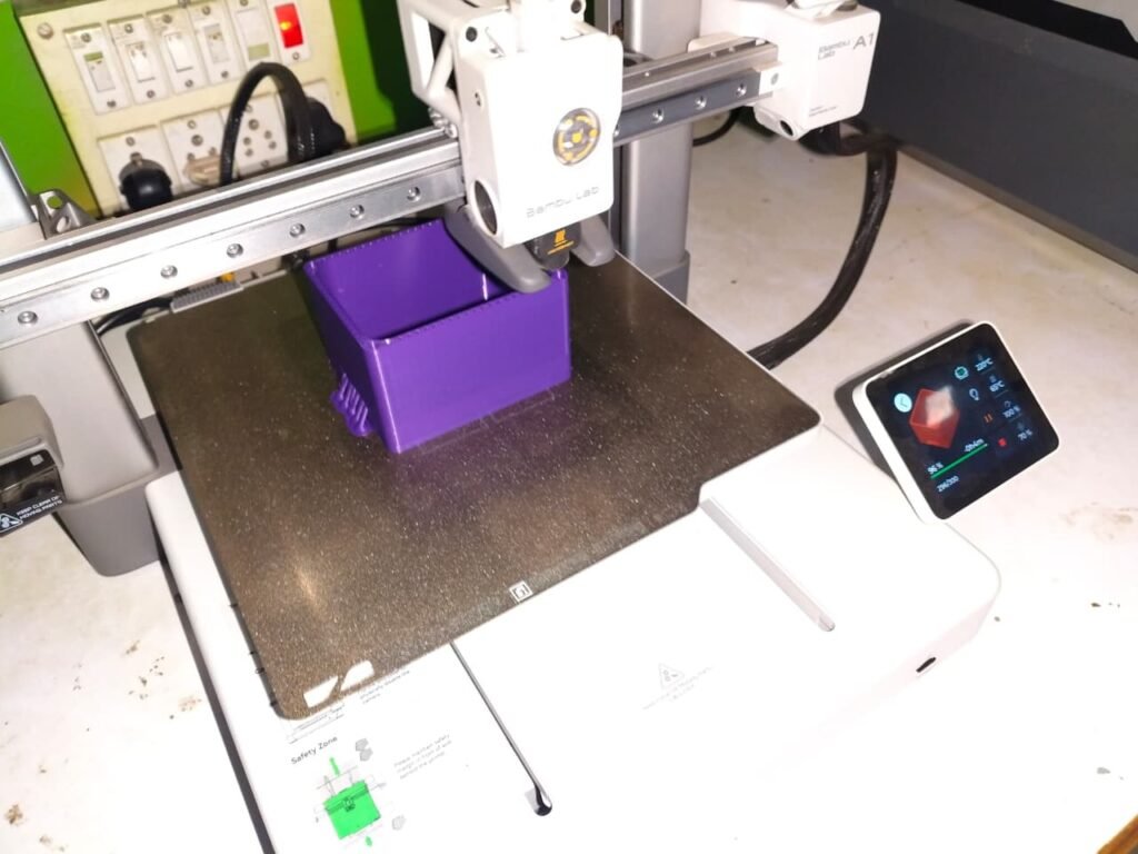
After completing the enclosure design in Fusion 360, I prepared the box and lid for 3D printing using Bambu Studio. I configured the required strength and support settings and then performed the slicing process using Slice All.
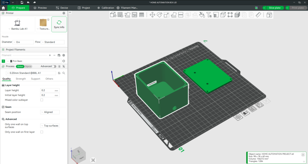
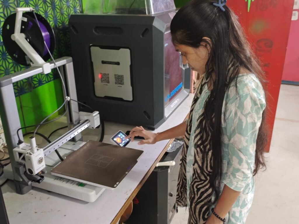
After slicing, I exported the G-code file and transferred it to the Bambu Lab A1 printer using an SD card. I then selected the file on the printer and started the printing process to manufacture the designed enclosure.
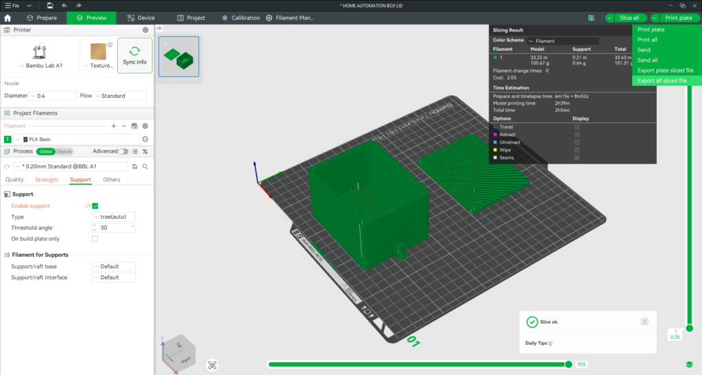
Printing Process:
Design in Fusion 360 → Bambu Studio → Strength & Support Settings → Slice All → Export G-code → Transfer via SD Card → Bambu Lab A1 → 3D Printing
Printing Details:
Print Time: 2 hours 54 minutes
Slicing Software: Bambu Studio
3D Printer: Bambu Lab A1
Material: PLA+
Filament Used: 101.31 gm
Step 11 – Soldering
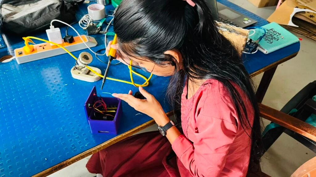
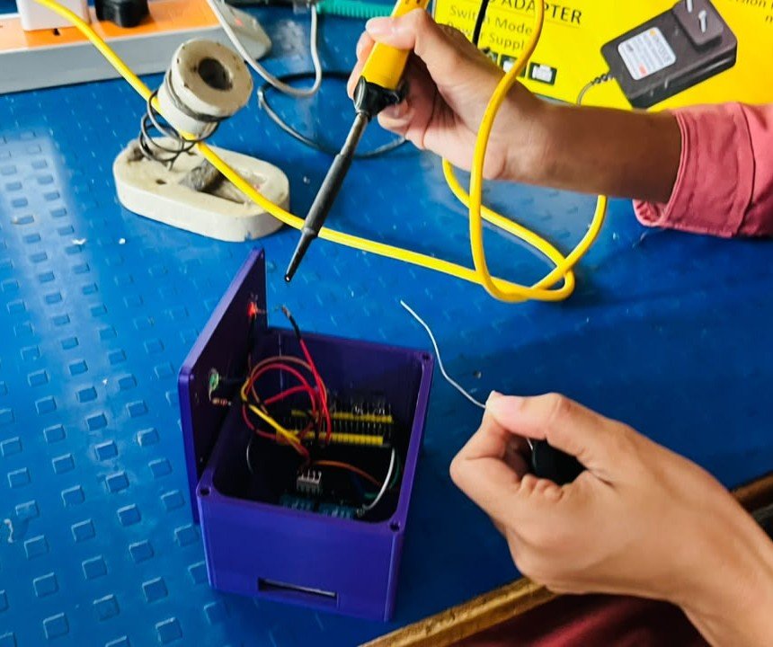
I soldered the required connections and attached connector to the relay and ESP32 for the required connections.I also soldered the 220Ω resistors to the indicator LEDs for the bulb and fan status indication.
I used heat-shrink sleeves over the required soldered joints to provide insulation and keep the connections neat.
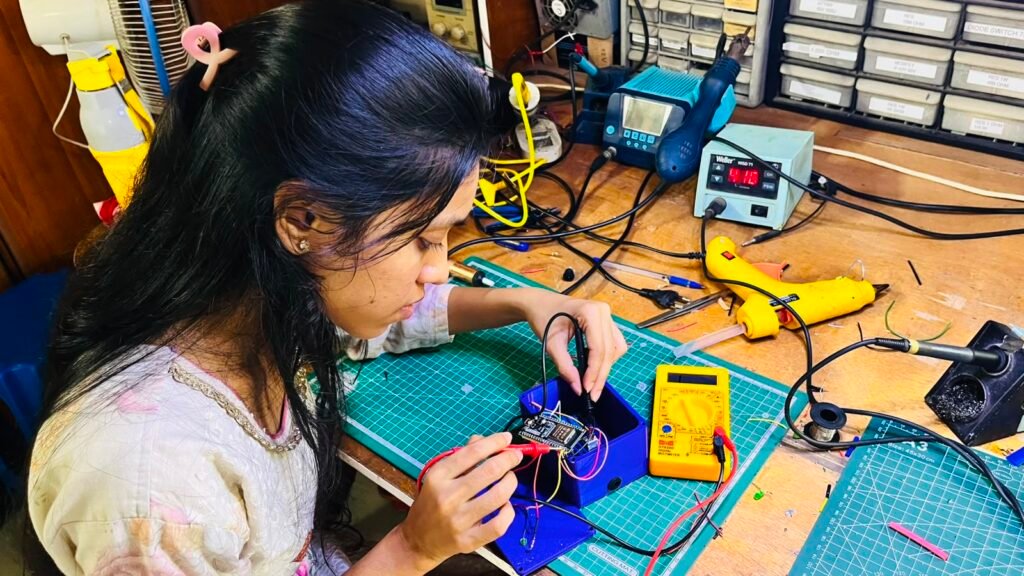
After completing the soldering and wiring, I checked all the connections using a multimeter.
Step 12 – Final Assembly
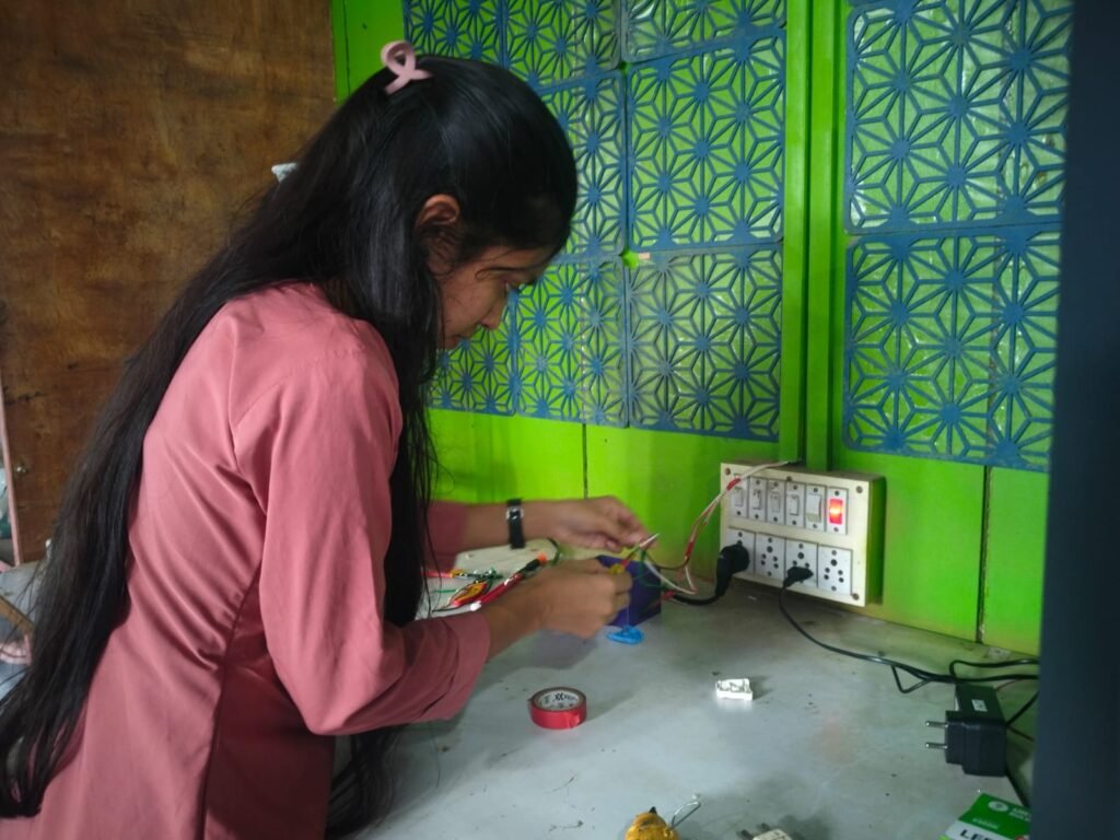
I completed the final wiring by connecting the incoming phase of bulb and fan to COM1 and COM2 of Relay 1 and Relay 2, while the NO1 and NO2 outputs of fan and bulb were connected through the two-pin connector.
The bulb and fan neutral connections were joined to the common neutral connection and connected to other connector of two pin.
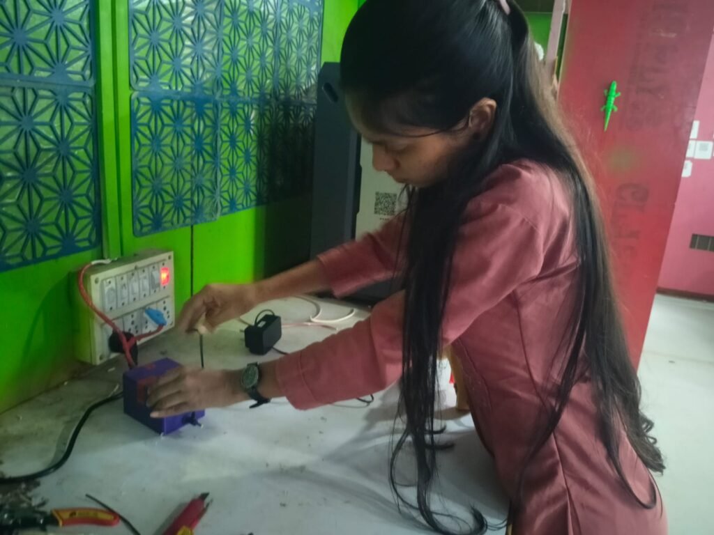
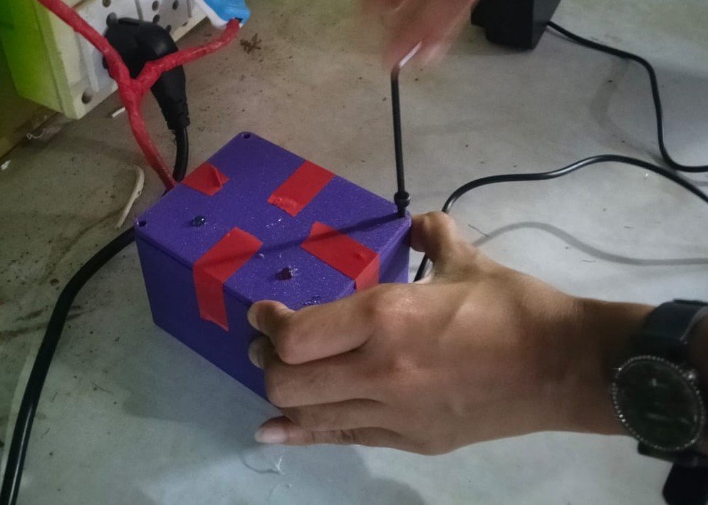
I then connected the two-pin connector to the board and provided the required power supply and also provided power supply to female connector mounted on the enclosure through 5 volt adapter. Finally, I secured the box with 4 mm screws and mounted the bulb and fan indicator LEDs on the front panel.
Complete System Testing Result
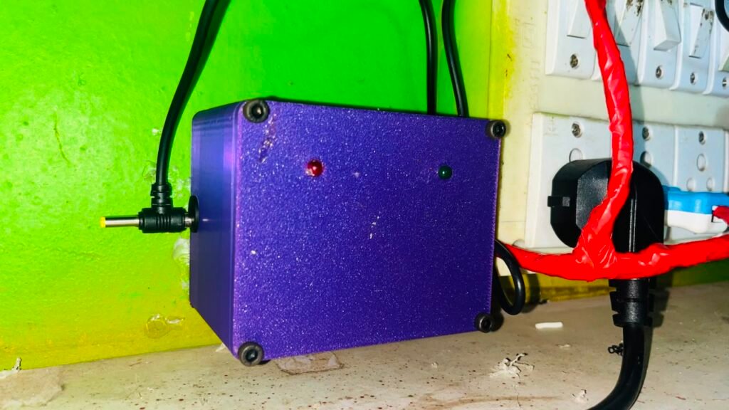
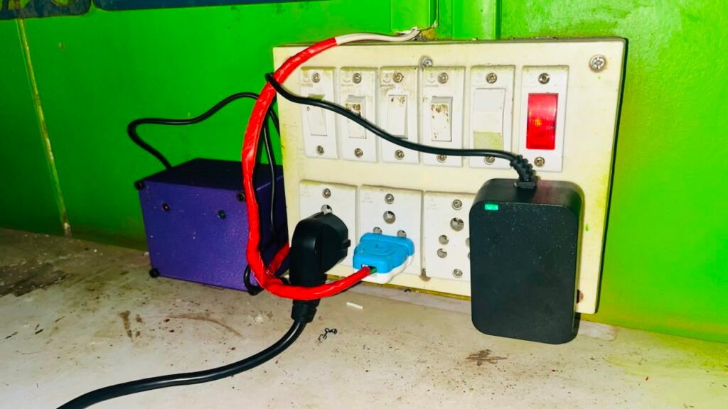
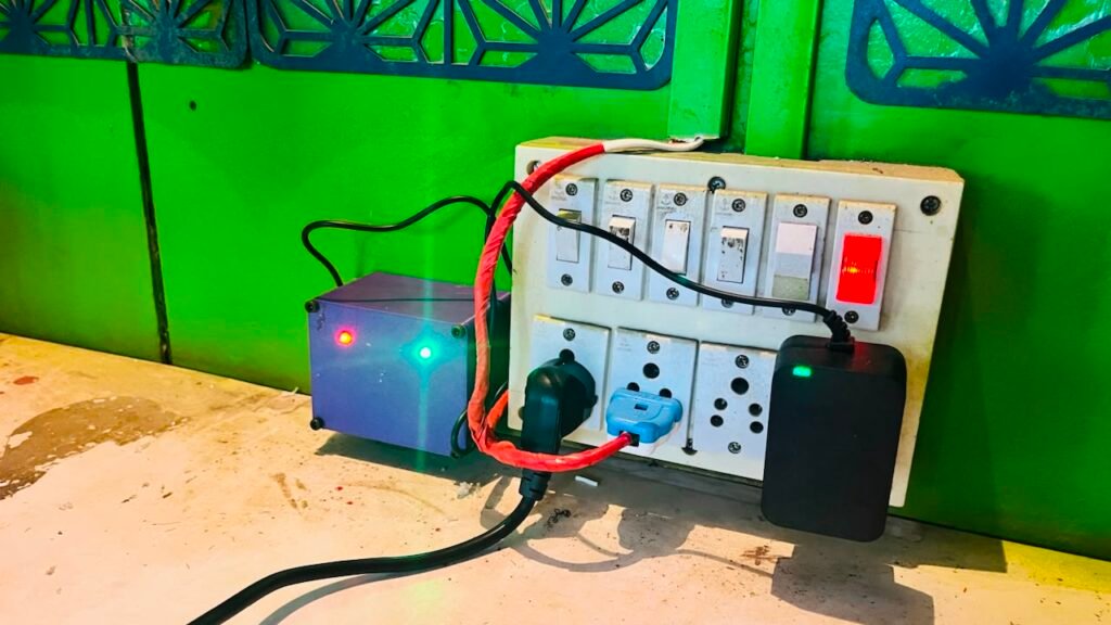
For the final testing, I switched ON the power supply through the two-pin connection and also powered the ESP32 using the adapter. The ESP32 powered ON and successfully connected to the configured Wi-Fi network.
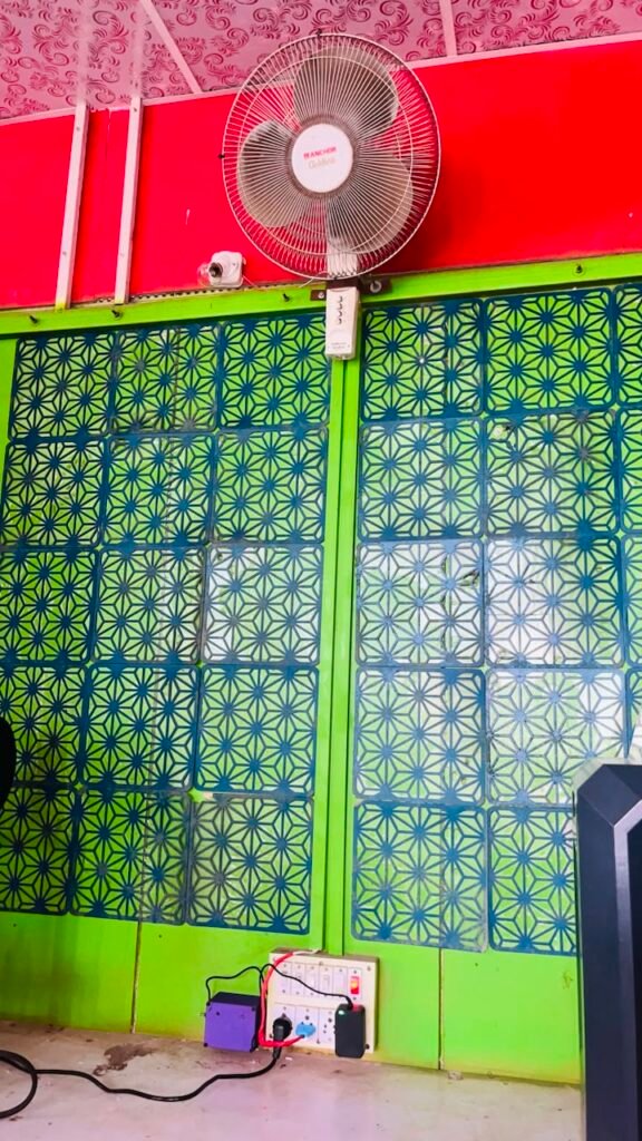
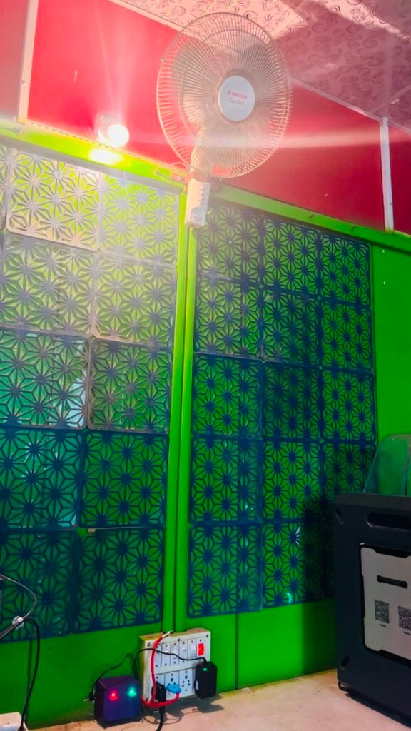
The ESP32 connected to Wi-Fi and Sinric Pro, allowing the bulb and fan to be controlled through the Amazon Alexa mobile application as well as voice commands. The relay module operated the appliances correctly, while the two indicator LEDs provided their status indication. The complete system was finally assembled in the 3D-printed enclosure and worked successfully as intended.:
Final Working Video
The Smart Home Automation System was successfully developed and tested.
Bill of Materials & Project Cost
The following table shows the approximate cost of the main components and materials. The costing is based on the actual purchase prices and the material used during fabrication.
| Component | Qty. | Unit Cost | Total |
|---|---|---|---|
| ESP32 38-Pin Development Board | 1 | ₹ 399.00 | ₹ 399.00 |
| 2-Channel 5V Relay Module | 1 | ₹ 95.00 | ₹ 95.00 |
| 5V SMPS / Power Supply | 1 | ₹ 150.00 | ₹ 150.00 |
| SMPS Female Connector | 1 | ₹ 3.00 | ₹ 3.00 |
| LED | 2 | ₹ 3.00 | ₹ 3.00 |
| 220Ω Resistor | 2 | ₹ 2.00 | ₹ 2.00 |
| Jumper Wires | 10 | ₹ 1.1 | ₹ 11 |
| Connectors | 1 | ₹ 7 | ₹ 7 |
| 3D Printing PLA/PLA+ Filament | 101 g | ₹0.78/g | ₹ 78.78 |
| Total | 748.78 |
Approximate cost: ₹748.78
Note: Soldering and other miscellaneous materials are not included in this calculation and can be added separately if required.
Challenges I Faced
- ESP32 Programming: While programming the ESP32, I faced some issues during code testing and debugging. I solved them by making changes and testing the code repeatedly.
- Wi-Fi Connection:I faced difficulty while establishing the Wi-Fi connection with the ESP32. I checked the connection through the Serial Monitor and verified that the ESP32 was connected successfully.
- Sinric Pro Integration: Setting up the Bulb and Fan devices and adding the required Device ID, App Key, and App Secret to the code required careful configuration.
- Alexa Integration: Connecting Sinric Pro with Amazon Alexa and testing the voice commands required proper account linking and repeated testing.
- Hardware Connections: The relay, ESP32, LEDs, connectors, and other wiring had to be checked carefully. I also used a multimeter to verify the connections.
- Enclosure Fitting: I adjusted the design according to the component arrangement.
Project Files
I have uploaded all the important project files in a Google Drive folder. The folder contains Fusion 360 design, STL files and other project-related files.
Project Files:
All Files Of The Alexa Smart Home Automation
Conclusion
The Wi-Fi Based Smart Home Automation System was successfully developed and tested using a 38-pin ESP32, 2-channel relay module, Sinric Pro, and Amazon Alexa. The system allows me to control a bulb and fan wirelessly as well as through voice commands, while the indicator LEDs show their operating status.
The project was developed step by step, from component testing and breadboard development to programming, IoT integration, enclosure design, 3D printing, and final assembly. The completed system worked successfully and provided a simple and convenient solution for controlling household appliances remotely.