Introduction
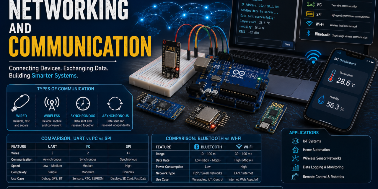
Week 5 focused on understanding how electronic devices communicate with each other and exchange information. In embedded systems, communication is an essential part of every project because sensors, microcontrollers, displays, mobile applications, and cloud platforms need to share data to perform useful tasks. This week introduced both the theoretical concepts of networking and the practical implementation of communication protocols commonly used in embedded systems and IoT applications.
Throughout this week, I studied the fundamentals of data communication, networking, communication protocols, wired and wireless communication, serial and parallel data transmission, synchronous and asynchronous communication, and several popular protocols including UART, I²C, SPI, One-Wire, Bluetooth, and Wi-Fi. Understanding these protocols helped me learn how different devices exchange information efficiently depending on the application requirements.
The practical assignments were equally interesting and helped me connect the theory with real-world implementation. I established wireless communication between two ESP32 boards using Wi-Fi, performed UART communication between two XIAO ESP32-C3 boards, controlled an LED using an Arduino Uno with an HC-06 Bluetooth module, designed a mobile application using MIT App Inventor to control an ESP32 over Wi-Fi, and developed an IoT-based temperature and humidity monitoring system using a DHT22 sensor and ThingSpeak Cloud.
By completing these activities, I gained hands-on experience in microcontroller communication, wireless networking, cloud-based data monitoring, and IoT application development. Overall, this week strengthened both my theoretical understanding and practical skills in networking and embedded communication.
Introduction to Networking and Communication
Modern embedded systems rarely work as standalone devices. Most embedded applications require communication with other hardware components such as sensors, displays, computers, smartphones, or cloud servers. The ability of these devices to exchange information accurately and efficiently is known as communication, while connecting multiple devices together to share information forms a network.
Networking and communication are the backbone of today’s smart technologies. Whether it is a smart home, industrial automation system, weather station, healthcare device, or agricultural monitoring system, all of these applications rely on communication between multiple electronic devices. Without communication, a sensor would not be able to send its readings to a microcontroller, a mobile application could not control an IoT device, and cloud platforms would not receive real-time information.
In embedded systems, communication takes place using predefined protocols. These protocols define how data is transmitted, received, synchronized, and interpreted between devices. Different protocols are designed for different purposes—some offer high-speed communication, while others are optimized for low power consumption, longer communication distance, or simpler hardware connections.
Learning networking and communication is important because it allows us to build reliable embedded systems that can exchange information with other devices, automate processes, and connect to the Internet for remote monitoring and control.
What is Data?
Data is any piece of information that can be collected, processed, stored, or transmitted between electronic devices. In embedded systems, data is usually generated by sensors, user inputs, switches, or other connected devices. A microcontroller processes this information and performs actions based on the received values.
Depending on the application, data can represent physical measurements, digital signals, text, numbers, or control commands. Once processed, the same data can be displayed on a screen, stored in memory, or transmitted to another device through a communication protocol.

Examples of Data
- Temperature = 30°C
- Humidity = 65%
- Distance = 25 cm
- Gas Detection = Detected
- LED Status = ON / OFF
- Motion Sensor Output = Motion Detected
In IoT projects, sensors continuously generate data, and microcontrollers transmit this information to cloud platforms where users can monitor it from anywhere in the world.
What is Communication?
Communication is the process of exchanging information between two or more electronic devices. In embedded systems, communication enables microcontrollers, sensors, actuators, displays, computers, and mobile phones to work together by sending and receiving data.
For communication to happen successfully, both devices must follow the same communication protocol and data format. Depending on the application, communication can be established using physical wires or wireless technologies such as Bluetooth and Wi-Fi.
Communication is one of the most important functions in embedded systems because it allows devices to share sensor readings, receive commands, control external hardware, and connect to cloud services.
Example
An ESP32 reads temperature and humidity values from a DHT22 sensor and sends the collected data to the ThingSpeak cloud platform through Wi-Fi. Similarly, a mobile application developed using MIT App Inventor can send commands to an ESP32 to switch an LED ON or OFF over the same Wi-Fi network.

What is Networking?
Networking is the process of connecting multiple electronic devices so they can communicate and exchange information with each other. These connected devices form a network, making it possible to share data, resources, and services efficiently.
A network may include computers, smartphones, microcontrollers, sensors, cloud servers, printers, or other smart devices. Depending on the communication medium, a network can be either wired or wireless.
In embedded systems and IoT, networking allows different devices to work together as a complete system. For example, an ESP32 can collect sensor readings, transmit them over Wi-Fi, store the data on a cloud server, and allow users to monitor the information through a mobile application.

Types of Networks
| Network | Description | Example |
|---|---|---|
| PAN (Personal Area Network) | Connects devices within a very short distance around a single user. | Smartphone connected to Bluetooth earbuds or smartwatch |
| LAN (Local Area Network) | Connects devices inside a home, office, laboratory, or school. | Home or office Wi-Fi network |
| MAN (Metropolitan Area Network) | Connects multiple local networks across a city or large campus. | University campus network |
| WAN (Wide Area Network) | Covers very large geographical areas and connects multiple networks together. | The Internet |
Advantages of Networking
- Enables fast and efficient data sharing.
- Supports communication between multiple devices.
- Makes remote monitoring and control possible.
- Improves automation in embedded and IoT systems.
- Allows devices to access shared resources.
- Increases system flexibility and scalability.
Applications of Networking
- Smart Home Automation
- Industrial Automation
- Weather Monitoring Systems
- Smart Agriculture
- Healthcare Monitoring
- IoT-Based Projects
- Environmental Monitoring Systems
What is a Communication Protocol?
A communication protocol is a predefined set of rules that allows two or more electronic devices to exchange data correctly and efficiently. These rules define how data is formatted, transmitted, received, synchronized, and verified during communication. Without a communication protocol, devices would not be able to understand each other’s data, even if they were physically connected.
Different embedded applications require different communication protocols depending on factors such as communication speed, transmission distance, number of connected devices, reliability, and power consumption.

Common Communication Protocols
- UART (Universal Asynchronous Receiver/Transmitter)
- I²C (Inter-Integrated Circuit)
- SPI (Serial Peripheral Interface)
- One-Wire
- Bluetooth
- Wi-Fi
Each protocol has its own advantages and is selected according to the application’s requirements.
Internet of Things (IoT)
The Internet of Things (IoT) refers to a network of physical devices that are connected to the internet and can collect, exchange, and process data automatically. These devices usually contain sensors, microcontrollers, communication modules, and software that enable them to communicate with cloud platforms or other smart devices.
IoT allows users to monitor and control devices remotely using smartphones, computers, or web applications. It plays an important role in automation by reducing manual work and enabling real-time decision-making.
A typical IoT system consists of four main components:
- Sensors – Collect environmental data such as temperature, humidity, motion, or light.
- Microcontroller – Processes the collected data and controls the connected devices.
- Communication Module – Transfers data through Wi-Fi, Bluetooth, or other communication technologies.
- Cloud Platform – Stores, analyzes, and displays the received information.
Applications of IoT
- Smart Home Automation
- Smart Agriculture
- Weather Monitoring Stations
- Healthcare Devices
- Industrial Automation
- Energy Monitoring Systems
- Smart City Infrastructure
Advantages of IoT
- Real-time monitoring
- Remote access and control
- Automatic data collection
- Improved efficiency
- Better decision-making using cloud analytics
- Reduced human intervention
Types of Communication
Communication in embedded systems is generally divided into Wired Communication and Wireless Communication.
1. Wired Communication
Wired communication transfers data through physical cables. Since the communication path is fixed, it offers stable and reliable data transmission with minimal interference. Most embedded systems use wired communication for short-distance connections between microcontrollers and peripheral devices.
Common Wired Protocols
- UART
- I²C
- SPI
- One-Wire
- Ethernet
Advantages
- Stable communication
- High reliability
- Low signal interference
- Faster communication for many applications
- Better security than wireless communication
Disadvantages
- Requires physical wiring
- Limited mobility
- Installation becomes difficult for large systems

2. Wireless Communication
Wireless communication transfers information without using physical wires. Instead, it uses radio waves or electromagnetic signals to exchange data between devices. Wireless communication is widely used in modern IoT applications because it offers flexibility and allows remote access.
Common Wireless Technologies
- Wi-Fi
- Bluetooth
- Zigbee
- LoRa
- NFC
- Cellular Networks (4G/5G)
Advantages
- No physical cables required
- Easy installation
- Supports remote monitoring
- Greater flexibility
- Suitable for IoT applications
Disadvantages
- Signal interference may occur
- Higher power consumption in some technologies
- Communication depends on signal strength
- Security must be properly managed

Data Transmission Methods
Electronic devices exchange information using two primary transmission methods:
- Serial Communication
- Parallel Communication
1. Serial Communication
In serial communication, data is transmitted one bit at a time through a single communication channel. Since fewer wires are required, serial communication is widely used in modern embedded systems and IoT devices.
Most communication protocols used with microcontrollers, such as UART, I²C, SPI, USB, and Ethernet, are based on serial communication.
Advantages
- Requires fewer wires
- Lower hardware cost
- Suitable for long-distance communication
- Less signal interference
- Easy to implement
Disadvantages
- Lower data transfer rate compared to parallel communication for certain applications
- Data is transmitted sequentially
Examples
- UART
- I²C
- SPI
- USB
- Ethernet
2. Parallel Communication
Parallel communication transfers multiple bits simultaneously using multiple data lines. Because several bits are transmitted together, the communication speed is high over short distances.
Parallel communication was widely used in older computer systems, printers, and memory interfaces. However, modern embedded systems generally prefer serial communication because it requires fewer wires and offers better reliability.
Advantages
- High data transfer speed
- Multiple bits transferred simultaneously
- Suitable for short-distance communication
Disadvantages
- Requires many wires
- Higher hardware cost
- Signal synchronization becomes difficult over long distances
- Increased chances of interference
Examples
- CPU to RAM communication
- Parallel LCD Interface
- Computer Data Bus
- Older Printer Ports
Communication Modes
Communication modes describe the direction in which data flows between devices. Depending on the application, communication may occur in one direction or both directions.
There are three main communication modes.
1. Simplex Communication
Simplex communication allows data to travel only in one direction. One device always acts as the transmitter, while the other only receives data. The receiver cannot send information back to the sender.
Examples
- Television broadcasting
- Radio broadcasting
- Keyboard sending data to a computer
Advantages
- Very simple communication
- Easy to implement
- Low cost
2. Half-Duplex Communication
Half-duplex communication allows data to travel in both directions, but only one device can transmit at a time. Before the other device sends data, the first device must stop transmitting.
Examples
- Walkie-talkies
- Two-way radio systems
Advantages
- Communication is possible in both directions
- Lower hardware complexity than full-duplex systems
3. Full-Duplex Communication
Full-duplex communication allows both devices to transmit and receive data simultaneously. This provides faster and more efficient communication because both devices can communicate at the same time.
Examples
- Mobile phone calls
- Video conferencing
- Ethernet communication
- UART communication
Advantages
- Faster communication
- Simultaneous transmission and reception
- Higher communication efficiency
Synchronous and Asynchronous Communication
Communication protocols can also be classified based on whether they use a common clock signal.
1. Synchronous Communication
In synchronous communication, both the transmitting and receiving devices share a common clock signal. This clock synchronizes data transmission, making communication faster and more reliable.
Examples
- SPI
- I²C
Advantages
- High communication speed
- Accurate synchronization
- Suitable for continuous data transfer
- Reliable data transmission
Disadvantages
- Requires an additional clock line
- Slightly more complex hardware

2. Asynchronous Communication
Asynchronous communication does not require a common clock signal. Instead, data is transmitted using start bits and stop bits, allowing the receiver to identify the beginning and end of each data frame.
UART is one of the most common asynchronous communication protocols used in embedded systems.
Examples
- UART
- Serial Monitor communication
- Communication between Arduino and computer
Advantages
- Simple hardware
- No clock wire required
- Easy implementation
- Low-cost communication
Disadvantages
- Lower efficiency due to start and stop bits
- Slower than synchronous communication

UART (Universal Asynchronous Receiver/Transmitter)
UART (Universal Asynchronous Receiver/Transmitter) is one of the simplest and most widely used serial communication protocols in embedded systems. It enables two electronic devices to exchange data without using a separate clock signal, which makes it an asynchronous communication protocol.
UART communication requires only two data lines:
- TX (Transmit) – Sends data to another device.
- RX (Receive) – Receives data from another device.
For successful communication, both devices must use the same baud rate (such as 9600, 57600, or 115200 bps).
Working Principle
In UART communication, one device sends data through its TX pin, while the receiving device reads the data through its RX pin. Since there is no clock signal, both devices must already be configured with the same communication settings. Every transmitted data packet contains a Start Bit, Data Bits, an optional Parity Bit, and one or more Stop Bits.
UART Frame Structure
| Part | Description |
|---|---|
| Start Bit | Indicates the beginning of data transmission |
| Data Bits | Actual information being transmitted |
| Parity Bit | Optional bit used for error detection |
| Stop Bit | Indicates the end of the transmitted data |
Features
- Asynchronous communication
- Uses only two communication lines
- Supports full-duplex communication
- Simple hardware connection
- Easy to program and debug
Applications
- Communication between Arduino and Computer
- GPS Modules
- GSM Modules
- Bluetooth Modules (HC-05 / HC-06)
- ESP32 Serial Communication
- Arduino IDE Serial Monitor
Advantages
- Simple implementation
- Low hardware cost
- Requires only TX and RX connections
- Reliable communication over short distances
Limitations
- Supports only point-to-point communication
- Lower speed compared to SPI
- No built-in addressing system
I²C (Inter-Integrated Circuit)
I²C (Inter-Integrated Circuit) is a synchronous serial communication protocol developed for communication between multiple integrated circuits using only two wires. It is one of the most commonly used communication protocols in embedded systems because many sensors and display modules support it.
Unlike UART, I²C allows multiple slave devices to communicate with a single master device through the same communication bus.
Communication Lines
| Pin | Function |
|---|---|
| SDA | Serial Data Line used for transferring data |
| SCL | Serial Clock Line generated by the Master |
Working Principle
In an I²C network, one device acts as the Master, while all other connected devices act as Slaves. Every slave device has a unique address. When communication starts, the Master sends the address of the required slave. Only the addressed device responds, while all other devices ignore the communication.
Because every device shares the same two wires, wiring becomes much simpler compared to other protocols.
Features
- Synchronous communication
- Uses only SDA and SCL lines
- Supports multiple slave devices
- Every device has a unique address
- Simple wiring
Applications
- OLED Displays
- LCD Display with I²C Module
- Real-Time Clock (RTC)
- EEPROM Memory
- Temperature Sensors
- Environmental Sensors
Advantages
- Requires only two wires
- Supports multiple devices
- Easy hardware expansion
- Low wiring complexity
Limitations
- Slower than SPI
- Best suited for short-distance communication
- Communication speed decreases with many connected devices
SPI (Serial Peripheral Interface)
SPI (Serial Peripheral Interface) is a high-speed synchronous communication protocol used for communication between microcontrollers and peripheral devices. It is much faster than UART and I²C because data can be transmitted and received simultaneously.
SPI is commonly used when high-speed communication is required.
SPI Communication Lines
| Pin | Function |
|---|---|
| MOSI | Master Out Slave In – Sends data from Master to Slave |
| MISO | Master In Slave Out – Sends data from Slave to Master |
| SCK | Serial Clock generated by the Master |
| CS / SS | Chip Select used to choose the Slave device |
Working Principle
The Master device first selects the required Slave using the Chip Select (CS) pin. After selecting the device, the Master generates the clock signal through the SCK line.
Data travels simultaneously in both directions:
- Master → Slave through MOSI
- Slave → Master through MISO
Because transmission occurs at the same time, SPI offers very high communication speed.
Features
- High-speed communication
- Full-duplex transmission
- Synchronous communication
- Separate transmit and receive lines
- Supports multiple slave devices
Applications
- SD Card Modules
- RFID RC522
- TFT Displays
- OLED Displays
- Flash Memory
- High-Speed Sensors
Advantages
- Very fast communication
- Simultaneous data transmission and reception
- Suitable for high-speed applications
- Reliable communication
Limitations
- Requires four communication wires
- Each slave needs an individual Chip Select pin
- Wiring becomes more complex as the number of devices increases
Comparison of UART, I²C and SPI
| Feature | UART | I²C | SPI |
|---|---|---|---|
| Communication Type | Serial | Serial | Serial |
| Clock Signal | Not Required | Required | Required |
| Communication Mode | Full Duplex | Half Duplex | Full Duplex |
| Number of Wires | 2 | 2 | 4 |
| Number of Devices | Two Devices | Multiple Devices | Multiple Devices |
| Speed | Medium | Medium | High |
| Addressing | No | Yes | No |
| Hardware Complexity | Very Low | Low | Medium |
| Best Applications | Computer Communication, GPS, GSM | Sensors, RTC, OLED, EEPROM | SD Cards, RFID, Displays |

Summary
Each communication protocol has its own strengths and is selected according to the application requirements.
- UART is simple, cost-effective, and ideal for communication between two devices.
- I²C is best when multiple sensors or peripherals need to communicate using only two wires.
- SPI provides the highest communication speed and is preferred for devices such as displays, memory modules, and RFID readers where fast data transfer is important.
Understanding these three protocols is essential because they are widely used in embedded systems, robotics, automation, and IoT projects. During this week’s practical sessions, I worked with UART communication between two XIAO ESP32-C3 boards and also used Wi-Fi communication with ESP32, which helped me understand how different communication protocols are implemented in real hardware.
One-Wire Communication
One-Wire is a simple serial communication protocol that allows multiple devices to communicate with a microcontroller using only one data wire and a common ground (GND) connection. It is mainly used for low-speed communication where simple wiring and low hardware cost are important.
Each device connected to a One-Wire bus contains a unique 64-bit identification number, allowing multiple devices to share the same communication line without conflicts.
Working Principle
The microcontroller communicates with one device at a time by using its unique address. Commands and data are transmitted over the same data line, reducing the number of wires required for communication.
Because only a single communication wire is used, One-Wire is ideal for applications where space is limited or the wiring needs to remain simple.
Features
- Uses only one communication wire
- Simple hardware connection
- Supports multiple devices on a single bus
- Every device has a unique 64-bit address
- Low-cost communication
Applications
- DS18B20 Temperature Sensor
- Digital Identification Systems
- iButton Devices
- Environmental Monitoring Systems
Advantages
- Very simple wiring
- Low hardware cost
- Easy to connect multiple devices
- Suitable for sensor applications
Limitations
- Lower communication speed
- Limited communication distance
- Not suitable for high-speed applications
Bluetooth Communication
Bluetooth is a wireless communication technology that enables devices to exchange data over short distances without using cables. It operates in the 2.4 GHz ISM frequency band and is commonly used for connecting mobile phones, laptops, wireless accessories, and embedded systems.
In embedded electronics, Bluetooth provides an easy way to control devices wirelessly using a smartphone or another Bluetooth-enabled device. Modules such as HC-05 and HC-06 are frequently used with Arduino boards, while ESP32 has built-in Bluetooth support.
Working Principle
Before communication begins, two Bluetooth devices must be paired. Once the pairing process is complete, they can exchange data wirelessly within the communication range.
For example, when a user presses a button in a mobile application, the Bluetooth module receives the command and sends it to the microcontroller, which then performs the required action, such as turning an LED ON or OFF.
Features
- Wireless communication
- Operates at 2.4 GHz
- Low power consumption
- Simple device pairing
- Suitable for short-range communication
Applications
- Wireless LED Control
- Home Automation
- Robot Control
- Wireless Sensor Networks
- Bluetooth Speakers
- Mobile Accessories
Advantages
- No physical wiring required
- Easy to configure
- Low power consumption
- Affordable communication solution
Limitations
- Short communication range
- Lower data transfer speed than Wi-Fi
- Performance may reduce due to interference
Wi-Fi Communication
Wi-Fi is one of the most widely used wireless communication technologies in modern embedded systems and IoT applications. It allows electronic devices to connect to a local network or the Internet for data exchange.
Unlike Bluetooth, Wi-Fi offers higher communication speed and longer range, making it suitable for cloud connectivity and remote monitoring applications.
Microcontrollers like the ESP32 have built-in Wi-Fi functionality, allowing them to communicate directly with cloud platforms, mobile applications, and web servers.
Working Principle
The microcontroller first connects to a Wi-Fi network using the SSID (network name) and password. After establishing the connection, it receives an IP address from the router.
Using this IP address, the device can communicate with:
- Other ESP32 boards
- Mobile applications
- Computers
- Cloud platforms such as ThingSpeak
The ESP32 can both send and receive data through the network, making it ideal for IoT applications.
Features
- High-speed wireless communication
- Internet connectivity
- Supports multiple connected devices
- Longer communication range than Bluetooth
- Built-in support on ESP32
Applications
- Smart Home Automation
- IoT Systems
- Weather Monitoring
- Cloud Data Logging
- Remote Device Control
- Smart Agriculture
Advantages
- High communication speed
- Internet connectivity
- Remote monitoring
- Supports cloud platforms
- Reliable for IoT applications
Limitations
- Higher power consumption than Bluetooth
- Requires Wi-Fi network availability
- Performance depends on network quality
Comparison Between Bluetooth and Wi-Fi
| Feature | Bluetooth | Wi-Fi |
|---|---|---|
| Communication Range | Short (≈10 m) | Long (Depends on Router) |
| Data Transfer Speed | Medium | High |
| Internet Required | No | Yes (for cloud applications) |
| Power Consumption | Low | Higher |
| Best Used For | Device-to-device communication | IoT and Internet connectivity |
| Common Applications | Wireless Control, Audio Devices | Cloud Monitoring, Remote Access |

Advantages of Networking and Communication
Networking and communication technologies have become an essential part of modern embedded systems. They allow multiple devices to exchange information efficiently and work together without human intervention.
Some major advantages include:
- Fast and reliable data transmission
- Easy communication between multiple devices
- Supports automation and smart systems
- Enables remote monitoring and control
- Reduces manual effort
- Simplifies data collection from sensors
- Makes cloud-based monitoring possible
- Improves system efficiency and scalability
- Supports real-time communication
- Widely used in IoT, robotics, healthcare, and industrial automation
Summary
Different communication protocols are designed for different purposes. UART is suitable for simple point-to-point communication, I²C allows multiple devices to communicate using only two wires, while SPI provides high-speed communication for demanding applications. One-Wire simplifies sensor connections using a single data line, Bluetooth enables short-range wireless communication, and Wi-Fi connects embedded devices to local networks and the Internet.
Understanding these communication methods is important because they form the foundation of modern embedded systems and IoT applications. By learning how each protocol works, it becomes easier to select the most appropriate communication method for different projects based on speed, distance, hardware complexity, and application requirements.
Group Assignment
1. Wireless Communication Between Two ESP32 Boards Using Wi-Fi
One of the group assignments for this week was to establish wireless communication between two ESP32 development boards using a Wi-Fi network. The objective of this activity was to understand how two microcontrollers can exchange data without using any physical communication wires.
Both ESP32 boards were connected to the same mobile hotspot, which acted as the local network. One ESP32 was configured as the Server (Receiver), while the second ESP32 acted as the Client (Sender). After both boards were connected to the same Wi-Fi network, the sender transmitted a text message to the receiver through the network. The receiver successfully displayed the received message in the Serial Monitor, confirming successful communication between the two devices.
This experiment demonstrated the basic concept of wireless communication used in many IoT applications where multiple ESP32 devices communicate over the same network.
Hardware Used
- ESP32 Development Board × 2
- USB Cable × 2
- Laptop
- Mobile Hotspot / Wi-Fi Network
Working Principle
The communication was established using the built-in Wi-Fi module available on the ESP32.
The first ESP32 was programmed as a Wi-Fi Server, which continuously waited for incoming client connections. Once connected, it listened for messages sent by the client.
The second ESP32 was programmed as a Wi-Fi Client. After connecting to the same Wi-Fi network, it established a connection with the server using the server’s IP address and transmitted a text message.
Whenever the server received the message, it displayed the received text on the Serial Monitor.
Receiver Code
#include <WiFi.h>const char* ssid = "YOUR_HOTSPOT_NAME";const char* password = "YOUR_PASSWORD";WiFiServer server(80);void setup() { Serial.begin(115200); WiFi.begin(ssid, password); while (WiFi.status() != WL_CONNECTED) { delay(500); Serial.print("."); } Serial.println(); Serial.println("Wi-Fi Connected"); Serial.print("Receiver IP Address: "); Serial.println(WiFi.localIP()); server.begin();}void loop() { WiFiClient client = server.available(); if (client) { while (client.connected()) { if (client.available()) { String message = client.readStringUntil('\n'); Serial.print("Received Message : "); Serial.println(message); } } client.stop(); }}Sender Code
#include <WiFi.h>const char* ssid = "YOUR_HOTSPOT_NAME";const char* password = "YOUR_PASSWORD";const char* serverIP = "192.168.43.100";void setup() { Serial.begin(115200); WiFi.begin(ssid, password); while (WiFi.status() != WL_CONNECTED) { delay(500); Serial.print("."); } Serial.println(); Serial.println("Connected Successfully");}void loop() { WiFiClient client; if (client.connect(serverIP, 80)) { client.println("Hello from ESP32"); client.stop(); } delay(2000);}Required Changes Before Uploading
Before uploading the programs to both ESP32 boards, a few values must be modified according to the available Wi-Fi network.
Receiver Board
Replace the following values:
const char* ssid = "YOUR_HOTSPOT_NAME";const char* password = "YOUR_PASSWORD";Sender Board
Replace these values:
const char* ssid = "YOUR_HOTSPOT_NAME";const char* password = "YOUR_PASSWORD";const char* serverIP = "RECEIVER_IP_ADDRESS";The serverIP should be replaced with the IP address displayed on the Receiver ESP32 Serial Monitor after it successfully connects to the Wi-Fi network.
How the Communication Works
- Upload the Receiver program to the first ESP32.
- Open the Serial Monitor and note the IP address assigned to the Receiver board.
- Enter this IP address in the Sender program.
- Upload the Sender program to the second ESP32.
- Connect both ESP32 boards to the same Wi-Fi hotspot.
- The Sender connects to the Receiver through the network.
- The Sender transmits the message.
- The Receiver displays the received message in the Serial Monitor.
Learning Outcome
Through this activity, I learned how ESP32 boards communicate over a wireless network using their built-in Wi-Fi capability. I understood the concepts of Client-Server Communication, IP Addressing, and Network-Based Data Transmission. I also learned how two microcontrollers can exchange information without any physical communication cable.
This experiment gave me a clear understanding of the basic networking concepts used in IoT systems, where multiple embedded devices communicate through the same local network or over the Internet. It also improved my debugging skills while configuring Wi-Fi credentials, identifying IP addresses, and testing successful communication between two ESP32 boards.


2. Wired Communication Between Two XIAO ESP32-C3 Boards Using UART
In the second group assignment, we established wired communication between two Seeed Studio XIAO ESP32-C3 boards using the UART (Universal Asynchronous Receiver-Transmitter) protocol. Unlike Wi-Fi communication, UART transfers data directly through physical wires, making it one of the simplest and most reliable communication methods for embedded systems.
In this setup, one XIAO ESP32-C3 board acted as the Transmitter, while the other worked as the Receiver. The TX (Transmit) pin of one board was connected to the RX (Receive) pin of the second board, and similarly the RX pin was connected to the TX pin. The GND pins of both boards were also connected together to provide a common reference.
Whenever a message was entered in the Serial Monitor of one board, it was transmitted through the UART interface and displayed on the Serial Monitor of the other board. Likewise, replies could also be sent in the opposite direction, allowing two-way communication between both microcontrollers.
Hardware Connections
| Board 1 | Board 2 |
|---|---|
| TX | RX |
| RX | TX |
| GND | GND |
Board 1 (Transmitter & Receiver)
#include <HardwareSerial.h>HardwareSerial mySerial(1);void setup() { Serial.begin(115200); mySerial.begin(9600, SERIAL_8N1, 20, 21); Serial.println("Type a message and press Enter");}void loop() { if (Serial.available()) { String msg = Serial.readStringUntil('\n'); msg.trim(); mySerial.println(msg); Serial.print("You : "); Serial.println(msg); } if (mySerial.available()) { String reply = mySerial.readStringUntil('\n'); reply.trim(); Serial.print("Board 2 : "); Serial.println(reply); }}Board 2 (Transmitter & Receiver)
#include <HardwareSerial.h>HardwareSerial mySerial(1);void setup() { Serial.begin(115200); mySerial.begin(9600, SERIAL_8N1, 20, 21); Serial.println("Ready");}void loop() { if (mySerial.available()) { String msg = mySerial.readStringUntil('\n'); msg.trim(); Serial.print("Board 1 : "); Serial.println(msg); } if (Serial.available()) { String reply = Serial.readStringUntil('\n'); reply.trim(); mySerial.println(reply); Serial.print("You : "); Serial.println(reply); }}Working Process
- Connected the TX pin of Board 1 to the RX pin of Board 2.
- Connected the RX pin of Board 1 to the TX pin of Board 2.
- Connected the GND pins of both boards.
- Uploaded the transmitter program to Board 1.
- Uploaded the receiver program to Board 2.
- Opened the Serial Monitor for both boards.
- Typed a message on one board and observed it appearing on the other board.
- Repeated the process in the opposite direction to verify two-way communication.
Learning Outcome
This experiment provided a practical understanding of UART serial communication between two microcontrollers. I learned the importance of correctly connecting TX and RX pins, configuring the same baud rate on both devices, and using the Serial Monitor for testing communication. It also helped me understand how UART is widely used for connecting GPS modules, Bluetooth modules, GSM modules, and communication between different embedded systems. The activity improved my debugging skills and gave me confidence in implementing wired communication in future embedded and IoT projects.


Individual Assignment
1. Bluetooth LED Control Using Arduino Uno and HC-06
For this individual assignment, I built a simple wireless LED control system using an Arduino Uno and an HC-06 Bluetooth module. The objective was to control an LED from a smartphone using Bluetooth communication.
The HC-06 module was paired with a Bluetooth Serial application installed on my Android phone. The application sent simple commands (1 and 0) to the Arduino through Bluetooth. The Arduino received these commands using serial communication and switched the LED ON or OFF accordingly.
This activity introduced me to the basics of Bluetooth communication, wireless control, and serial data exchange between a mobile phone and a microcontroller.
Components Used
- Arduino Uno
- HC-06 Bluetooth Module
- LED
- 220Ω Resistor
- Breadboard
- Jumper Wires
- Android Mobile Phone
- Bluetooth Serial App
HC-06 Connections
| HC-06 Pin | Arduino Uno |
|---|---|
| VCC | 5V |
| GND | GND |
| TXD | RX (D0) |
| RXD | TX (D1) |
The LED was connected to Digital Pin 8 through a current-limiting resistor.
Mobile Commands
The Bluetooth Serial application was configured to send the following characters:
- 1 → Turn LED ON
- 0 → Turn LED OFF
The Arduino continuously monitored the incoming serial data and controlled the LED based on the received command.
Arduino Code
char data;int ledPin = 8;void setup() { pinMode(ledPin, OUTPUT); Serial.begin(9600);}void loop() { if (Serial.available()) { data = Serial.read(); if (data == '1') { digitalWrite(ledPin, HIGH); } if (data == '0') { digitalWrite(ledPin, LOW); } }}Working Procedure
- Connected the HC-06 Bluetooth module to the Arduino Uno.
- Connected the LED to Digital Pin 8 using a resistor.
- Uploaded the Arduino program.
- Powered the Arduino board.
- Paired the HC-06 module with the smartphone using Bluetooth.
- Opened the Bluetooth Serial application.
- Connected the application to the HC-06 module.
- Sent the command 1 to switch the LED ON.
- Sent the command 0 to switch the LED OFF.
- Verified that the LED responded correctly to each command.
Learning Outcome
Through this assignment, I gained practical experience in Bluetooth-based wireless communication. I learned how an HC-06 module communicates with an Arduino using serial communication and how a smartphone application can be used to send commands to control electronic devices remotely. This activity strengthened my understanding of Bluetooth interfacing, Arduino programming, and basic wireless automation concepts, which are widely used in IoT and home automation projects.


2. LED Control Using MIT App Inventor and ESP32
In this assignment, I developed a simple Android application using MIT App Inventor to control an LED connected to an ESP32 over a Wi-Fi network. The application included two buttons, ON and OFF, which sent commands to the ESP32 through its IP address. The ESP32 received these commands using a web server and changed the state of the LED accordingly.
This activity introduced me to mobile app development, Wi-Fi communication, and IoT-based device control. It also demonstrated how smartphones can be used to control embedded systems without requiring any additional hardware.
What is MIT App Inventor?
MIT App Inventor is a free, web-based platform developed by the Massachusetts Institute of Technology (MIT) for creating Android applications using block-based programming. Instead of writing traditional code, users can build applications by dragging and connecting programming blocks.
It is widely used for learning Android application development, IoT projects, and rapid prototyping because it is simple, visual, and beginner-friendly.
Features of MIT App Inventor
- Block-based programming
- Drag-and-drop user interface
- Easy Android app development
- Supports Wi-Fi, Bluetooth, Sensors, GPS, Camera, and Web components
- No advanced programming knowledge required
- Ideal for IoT and embedded system projects
Steps Followed
- Opened the MIT App Inventor website.
- Signed in using a Google account.
- Created a new project.
- Designed the user interface with ON and OFF buttons.
- Added the required Web component.
- Created the block programming logic for both buttons.
- Generated the APK/QR Code.
- Installed the application on the Android phone.
- Connected the mobile phone to the same Wi-Fi network as the ESP32.
- Tested the application by controlling the LED.
ESP32 Program
#include <WiFi.h>#include <WebServer.h>const char* ssid = "YOUR_WIFI_NAME";const char* password = "YOUR_WIFI_PASSWORD";WebServer server(80);const int ledPin = 2;void handleOn() { digitalWrite(ledPin, HIGH); server.send(200, "text/plain", "LED ON");}void handleOff() { digitalWrite(ledPin, LOW); server.send(200, "text/plain", "LED OFF");}void setup() { Serial.begin(115200); pinMode(ledPin, OUTPUT); digitalWrite(ledPin, LOW); WiFi.begin(ssid, password); while (WiFi.status() != WL_CONNECTED) { delay(500); Serial.print("."); } Serial.println(); Serial.print("ESP32 IP Address : "); Serial.println(WiFi.localIP()); server.on("/on", handleOn); server.on("/off", handleOff); server.begin();}void loop() { server.handleClient();}ESP32 Configuration
To establish communication between the mobile application and the ESP32, the Wi-Fi SSID and Password were entered into the Arduino program before uploading it to the board.
After connecting successfully to the Wi-Fi network, the ESP32 displayed its IP address on the Serial Monitor. This IP address was then entered into the MIT App Inventor blocks so that the application could send HTTP requests directly to the ESP32.
Since the web server runs on the ESP32 itself, both the smartphone and the ESP32 must remain connected to the same Wi-Fi network during operation.
Learning Outcome
This assignment gave me practical experience in developing a simple Android application and integrating it with an ESP32 using Wi-Fi communication. I learned how to create a user interface in MIT App Inventor, use block programming to send HTTP requests, configure the ESP32 as a web server, and control hardware remotely through a mobile application. This project strengthened my understanding of IoT concepts, wireless communication, and mobile-based embedded system control.


3. Temperature and Humidity Monitoring Using ESP32, DHT22, and ThingSpeak
In this assignment, I built a simple IoT-based environmental monitoring system using an ESP32 and a DHT22 temperature and humidity sensor. The ESP32 collected temperature and humidity readings from the sensor and transmitted the data to the ThingSpeak cloud platform through a Wi-Fi connection.
Once the data reached ThingSpeak, it was automatically stored and displayed as live graphs. This made it possible to monitor environmental conditions remotely from any device with internet access. Through this project, I gained hands-on experience with sensor interfacing, cloud platforms, wireless networking, and IoT-based data monitoring.
What is ThingSpeak?
ThingSpeak is an IoT cloud platform that allows users to collect, store, visualize, and analyze data from sensors and embedded devices. It is commonly used with boards such as Arduino, ESP32, and ESP8266 for real-time monitoring applications.
ThingSpeak provides channels where sensor values can be uploaded using an API key. The received data is displayed as graphs and charts, making it easy to observe changes over time.
Features of ThingSpeak
- Cloud-based IoT platform
- Real-time data visualization
- Graphical representation of sensor values
- Supports multiple data fields
- Easy integration with ESP32 and Arduino
- Secure data transmission using API Keys
Steps Followed
- Created a free ThingSpeak account.
- Logged into the ThingSpeak dashboard.
- Created a new channel.
- Added two fields:
- Temperature
- Humidity
- Saved the channel.
- Copied the Channel ID and Write API Key.
- Connected the DHT22 sensor to the ESP32.
- Installed the required Arduino libraries.
- Entered the Wi-Fi credentials, Channel ID, and API Key into the program.
- Uploaded the code to the ESP32.
- Verified successful data upload through the Serial Monitor.
- Observed live temperature and humidity graphs on the ThingSpeak dashboard.
Arduino Code
#include <WiFi.h>#include <DHT.h>#include <ThingSpeak.h>const char* ssid = "YOUR_WIFI_NAME";const char* password = "YOUR_WIFI_PASSWORD";unsigned long channelID = YOUR_CHANNEL_ID;const char* apiKey = "YOUR_WRITE_API_KEY";#define DHTPIN 4#define DHTTYPE DHT22DHT dht(DHTPIN, DHTTYPE);WiFiClient client;void setup() { Serial.begin(115200); dht.begin(); WiFi.begin(ssid, password); while (WiFi.status() != WL_CONNECTED) { delay(500); Serial.print("."); } Serial.println("\nWi-Fi Connected"); ThingSpeak.begin(client);}void loop() { float temperature = dht.readTemperature(); float humidity = dht.readHumidity(); if (isnan(temperature) || isnan(humidity)) { Serial.println("Sensor Error"); delay(2000); return; } ThingSpeak.setField(1, temperature); ThingSpeak.setField(2, humidity); int response = ThingSpeak.writeFields(channelID, apiKey); if (response == 200) { Serial.println("Data Uploaded Successfully"); } else { Serial.print("Upload Failed : "); Serial.println(response); } delay(20000);}Learning Outcome
This assignment helped me understand how IoT devices collect real-world data and send it to a cloud platform for remote monitoring. I learned how to interface the DHT22 sensor with an ESP32, connect the board to a Wi-Fi network, configure ThingSpeak using the Channel ID and Write API Key, and upload live sensor data to the cloud. It also improved my knowledge of cloud computing, wireless communication, and real-time IoT applications.


Week 5 – Overall Experience
Week 5 provided me with a strong foundation in Networking and Communication within embedded systems. Throughout the week, I explored both wired and wireless communication methods and learned how different devices exchange data efficiently.
I successfully implemented UART communication between two XIAO ESP32-C3 boards, established wireless communication between two ESP32 boards using Wi-Fi, controlled an LED using an HC-06 Bluetooth module, created a mobile application with MIT App Inventor to control an ESP32 over Wi-Fi, and developed an IoT-based temperature and humidity monitoring system using the DHT22 sensor and ThingSpeak.
These practical activities enhanced my understanding of communication protocols, IoT platforms, mobile application development, cloud-based monitoring, and embedded programming. I also improved my troubleshooting skills while configuring Wi-Fi connections, serial communication, Bluetooth pairing, and cloud data transmission.
Overall, this week gave me valuable hands-on experience with UART, Wi-Fi, Bluetooth, MIT App Inventor, ESP32, DHT22, and ThingSpeak, and strengthened my confidence in developing connected embedded systems and IoT applications.