Introduction
Output devices are an important part of electronic and embedded systems that allow a system to communicate with the external world. These devices receive signals from a microcontroller or processing unit and convert them into meaningful outputs such as light, sound, movement, or displayed information.
In embedded systems, output devices are used to perform specific actions based on the instructions given by the programmed controller. For example, an LED can provide visual indication, a buzzer can generate alerts, a motor can create mechanical movement, and displays can show real-time information.
During this week, I learned about different types of output devices, their working principles, interfacing methods, and practical applications in electronic projects. I explored how microcontrollers like Arduino Uno and Seeed XIAO ESP32-C3 can be used to control different output devices and create interactive systems.
Understanding output devices helped me learn how electronic systems provide feedback and interact with users and the physical environment.
What is an Output Device?
An output device is an electronic component that receives signals from a microcontroller or processing unit and converts them into a physical output that can be understood by humans or used to control other systems.
In embedded systems, the microcontroller processes input data from sensors and sends control signals to output devices to perform specific actions. These outputs can be in the form of light, sound, movement, display information, or switching operations.
Output devices act as a communication link between an electronic system and the external environment. They help users understand the system status and allow machines to perform automated tasks.
Examples of Output Devices:
- LED → Provides visual indication through light
- Buzzer → Generates sound alerts
- LCD/OLED Display → Shows text and information
- Relay Module → Controls high-power electrical devices
- Servo Motor → Provides controlled angular movement
- DC Motor → Produces rotational motion
Basic Working:
Input Device → Microcontroller → Output Device
Example:
Temperature Sensor → Arduino/ESP32 → OLED Display + Buzzer
The sensor collects data, the microcontroller processes it according to the program, and the output device provides the required response.
Output devices are essential in embedded systems because they enable interaction between electronic circuits and the real world.

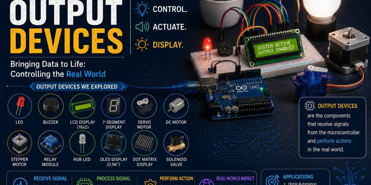
Output Devices Explored During This Week
During this week, I explored various output devices commonly used in embedded systems. These devices receive control signals from a microcontroller and convert them into different forms of output such as light, sound, motion, display, or switching operations. By studying their working principles and practical applications, I gained a better understanding of how embedded systems interact with the physical world.
The following output devices were explored during this week:
- LED (Light Emitting Diode) – Used for visual indication and status monitoring.
- RGB LED – Produces multiple colors by combining red, green, and blue LEDs.
- Buzzer – Generates sound for alarms and notifications.
- Dot Matrix Display – Displays characters, numbers, and simple animations.
- OLED Display – Shows high-quality text and graphics with low power consumption.
- 16×2 LCD Display – Displays alphanumeric information such as sensor readings and messages.
- Yellow BO Motor – A geared DC motor commonly used in robotics and small automation projects.
- Servo Motor – Provides precise angular movement for positioning applications.
- Relay Module – Acts as an electrically controlled switch for operating high-power electrical devices.
- Stepper Motor – Rotates in fixed steps, making it suitable for precise motion control.
- DC Fan – Converts electrical energy into rotational motion to generate airflow for cooling and ventilation.
These output devices demonstrated how different types of outputs can be generated using a microcontroller, enabling the development of interactive, automated, and intelligent electronic systems.
1. LED (Light Emitting Diode)
A Light Emitting Diode (LED) is one of the most commonly used output devices in electronics and embedded systems. It is a semiconductor device that emits light when an electric current flows through it in the forward direction. LEDs are widely used to provide visual indications, display system status, and illuminate electronic circuits due to their low power consumption, high efficiency, and long operational life. They are available in various colors and sizes, making them suitable for a wide range of applications, including consumer electronics, automotive lighting, industrial systems, and IoT projects.

2. RGB LED (Red Green Blue LED)
An RGB LED is a special type of LED that combines three individual LEDs — Red, Green, and Blue — inside a single package. By controlling the intensity of each color channel, an RGB LED can produce a wide range of colors. It is commonly used in electronic projects for visual indication, decorative lighting, displays, and interactive applications. RGB LEDs are controlled using microcontrollers by varying the input signals, usually through PWM (Pulse Width Modulation), to achieve different color combinations.

3. Buzzer
A buzzer is an electronic output device that converts electrical energy into sound energy. It is commonly used in embedded systems to provide audio feedback, alerts, and notifications to users. When an electrical signal is applied to the buzzer, it produces sound through electromagnetic or piezoelectric vibration. Buzzers are widely used in alarm systems, security devices, automation projects, and electronic circuits where an audio indication is required.
Buzzer can be easily controlled using microcontrollers like Arduino Uno, ESP32, and Seeed XIAO ESP32-C3 by providing digital signals to turn it ON or OFF.

4. Dot Matrix Display
A Dot Matrix Display is an electronic output device that uses a collection of small LEDs arranged in a matrix pattern of rows and columns to display characters, numbers, symbols, and simple animations. Each individual LED acts as a pixel, and by controlling different LEDs in the matrix, various patterns and messages can be created.
Dot Matrix Displays are commonly used in embedded systems, digital clocks, information boards, scrolling text displays, and interactive electronic projects. These displays can be controlled using microcontrollers like Arduino, ESP32, and Raspberry Pi by sending signals to control the rows and columns of LEDs.

5. OLED Display (Organic Light Emitting Diode Display)
An OLED (Organic Light Emitting Diode) Display is an advanced electronic output device used to display text, images, and graphical information. Unlike traditional LCD displays, OLED displays do not require a separate backlight because each pixel produces its own light using organic semiconductor materials.
OLED displays provide high contrast, better viewing angles, fast response time, and low power consumption, making them suitable for compact embedded systems. They are widely used with microcontrollers like Arduino, ESP32, and Raspberry Pi for displaying sensor data, system status, and user interfaces in electronic projects.
OLED displays are commonly available in small sizes such as 0.96-inch and 1.3-inch, and they usually communicate with microcontrollers using I2C or SPI communication protocols.

6. LCD Display (Liquid Crystal Display)
An LCD (Liquid Crystal Display) is an electronic output device used to display text, numbers, and basic graphical information. It works by controlling liquid crystal molecules using electrical signals to allow or block light passing through the display layers.
LCD displays are widely used in embedded systems because they are affordable, easy to interface, and provide a simple way to display real-time information such as sensor values, messages, and system status. The commonly used 16×2 LCD display consists of 16 columns and 2 rows, allowing it to display 32 characters at a time.
LCD displays are usually interfaced with microcontrollers like Arduino, ESP32, and Raspberry Pi using parallel communication or I2C communication modules, which reduce the number of required connections.

7. Servo Motor (SG90)
A Servo Motor SG90 is a compact output device used for precise angular movement and position control in electronic and embedded systems. Unlike a normal DC motor, a servo motor can rotate its shaft to a specific angle according to the control signal provided by a microcontroller.
The SG90 servo motor consists of a small DC motor, gear mechanism, control circuit, and position feedback system. It is commonly controlled using PWM (Pulse Width Modulation) signals generated by microcontrollers like Arduino, ESP32, and Raspberry Pi. By changing the PWM pulse width, the position of the motor shaft can be controlled accurately.
SG90 servo motors are widely used in robotics, automation systems, robotic arms, camera positioning systems, and various DIY electronic projects because of their small size, low cost, and easy interfacing.

8. Yellow BO Motor (Geared DC Motor)
A Yellow BO Motor is a small geared DC motor commonly used in robotics, automation projects, and small mechanical systems. It converts electrical energy into rotational mechanical motion using the principle of electromagnetic induction. The built-in gearbox reduces the motor speed and increases the torque, making it suitable for driving robot wheels and other moving mechanisms.
The motor consists of a DC motor, gear reduction system, shaft, and protective plastic housing. When voltage is applied, current flows through the motor coil, creating a magnetic field that interacts with permanent magnets and produces rotation. The gearbox transfers this rotation to the output shaft with higher torque.
Yellow BO motors are widely used with motor driver modules and microcontrollers like Arduino, ESP32, and Raspberry Pi for controlling robotic vehicles, line-following robots, and automation systems.

9. Relay Module
A Relay Module is an electronic output device that works as an electrically controlled switch. It allows a low-voltage microcontroller such as Arduino, ESP32, or Raspberry Pi to control high-voltage and high-current devices safely. A relay provides electrical isolation between the control circuit and the load circuit, making it useful for automation and control applications.
A relay works using the principle of electromagnetic switching. When current flows through the relay coil, it creates a magnetic field that attracts an internal armature, changing the position of switch contacts. This allows the connected load to be turned ON or OFF according to the control signal from the microcontroller.
Relay modules are commonly used in home automation, industrial control systems, motor control, lighting systems, and IoT-based projects where a small control signal needs to operate a powerful electrical device.

10. Stepper Motor
A Stepper Motor is an electronic output device that converts electrical pulses into precise mechanical rotational movement. Unlike a normal DC motor, a stepper motor rotates in fixed angular steps, allowing accurate control of position, speed, and direction without requiring a feedback system.
A stepper motor works by using electromagnetic fields generated by multiple coils placed around a rotor. When electrical pulses are supplied to these coils in a specific sequence, the rotor moves step-by-step to achieve the desired position.
Stepper motors are widely used in applications where precise movement is required, such as 3D printers, CNC machines, robotics, scanners, and automation systems. They are commonly controlled using motor driver modules with microcontrollers like Arduino, ESP32, and Raspberry Pi.

Individual Assignment
During this week, I worked on interfacing different output devices with the Seeed XIAO ESP32-C3 microcontroller. The objective of this assignment was to understand how a microcontroller controls different types of output devices and generates various forms of output such as light, sound, display, switching, and mechanical movement.
I connected and tested multiple output devices including LED, RGB LED, Buzzer, Dot Matrix Display, OLED Display, LCD Display, Yellow BO Motor, Servo Motor, Relay Module, and Stepper Motor with the XIAO ESP32-C3. Each device was programmed using Arduino IDE and its working was observed practically.
1. LED (Light Emitting Diode)
The LED (Light Emitting Diode) is a semiconductor output device that converts electrical energy into light energy. It is one of the most commonly used output devices in electronics and embedded systems for providing visual indications and displaying system status.
The LED works on the principle of electroluminescence, where light is produced when current flows through the semiconductor junction. LEDs are available in different colors and are widely used because of their low power consumption, fast switching speed, and long lifespan.
Practical Activity
In this activity, the LED was connected with the Seeed XIAO ESP32-C3 microcontroller and programmed using Arduino IDE. A digital output signal was provided from the microcontroller to control the ON and OFF state of the LED.
After uploading the code, the LED successfully turned ON and OFF according to the programmed instructions. Through this experiment, I learned how a microcontroller can control visual output devices and provide indications in embedded systems.


Code Used For LED
#define LED_PIN 4void setup() { pinMode(LED_PIN, OUTPUT);}void loop() { digitalWrite(LED_PIN, HIGH); delay(1000); digitalWrite(LED_PIN, LOW); delay(1000);}Observation
The LED was successfully interfaced with the XIAO ESP32-C3 and controlled through digital output signals. The experiment demonstrated the basic working of an output device and how a microcontroller can generate visual indications by controlling electronic components.
2. RGB LED (Red Green Blue LED)
An RGB LED is a type of output device that combines three individual LEDs — Red, Green, and Blue — inside a single package. By controlling the brightness of each color channel, an RGB LED can produce different colors and is widely used for visual indication, decorative lighting, and interactive electronic projects.
RGB LEDs are controlled using a microcontroller by providing separate signals to the three colour pins. By using PWM (Pulse Width Modulation), the intensity of each LED colour can be adjusted to generate multiple colour combinations.
Practical Activity
In this activity, the RGB LED was connected with the Seeed XIAO ESP32-C3 microcontroller and programmed using Arduino IDE. The three color channels (Red, Green, and Blue) were controlled individually using digital output and PWM signals from the microcontroller.
After uploading the program, different colors were generated by changing the intensity of the RGB channels. Through this experiment, I learned how a microcontroller can control multiple outputs simultaneously and create different visual effects using a single output device.


Code Used For RGB LED
#define RED_PIN 4#define GREEN_PIN 5#define BLUE_PIN 6void setup() { pinMode(RED_PIN, OUTPUT); pinMode(GREEN_PIN, OUTPUT); pinMode(BLUE_PIN, OUTPUT);}void loop() { // Red Color analogWrite(RED_PIN, 255); analogWrite(GREEN_PIN, 0); analogWrite(BLUE_PIN, 0); delay(1000); // Green Color analogWrite(RED_PIN, 0); analogWrite(GREEN_PIN, 255); analogWrite(BLUE_PIN, 0); delay(1000); // Blue Color analogWrite(RED_PIN, 0); analogWrite(GREEN_PIN, 0); analogWrite(BLUE_PIN, 255); delay(1000);}Observation
The RGB LED was successfully interfaced with the XIAO ESP32-C3 and different colors were generated by controlling the Red, Green, and Blue channels. This experiment demonstrated the use of PWM signals for controlling output intensity and creating multiple visual outputs using a microcontroller.bd268
3. Buzzer
A Buzzer is an electronic output device that converts electrical energy into sound energy. It is commonly used in embedded systems to provide audio feedback, alerts, and notifications. Buzzers are widely used in alarm systems, security devices, automation projects, and electronic circuits where sound indication is required.
A buzzer works using the piezoelectric effect or electromagnetic principle, where an electrical signal causes internal components to vibrate and produce sound. It can be easily controlled using a microcontroller by providing digital signals to turn it ON or OFF.
Practical Activity
In this activity, the Buzzer was connected with the Seeed XIAO ESP32-C3 microcontroller and programmed using Arduino IDE. A digital output signal was provided from the microcontroller to control the buzzer operation.
After uploading the code, the buzzer produced sound according to the programmed instructions. Through this experiment, I learned how microcontrollers can generate audio outputs and how buzzers are used for alerts and notifications in embedded systems.


Code Used For Buzzer
#define BUZZER_PIN 4void setup() { pinMode(BUZZER_PIN, OUTPUT);}void loop() { digitalWrite(BUZZER_PIN, HIGH); delay(1000); digitalWrite(BUZZER_PIN, LOW); delay(1000);}Observation
The buzzer was successfully interfaced with the XIAO ESP32-C3 and generated sound output when a digital signal was provided from the microcontroller. This experiment demonstrated how an embedded system can provide audio feedback using an output device.
4. Dot Matrix Display
A Dot Matrix Display is an electronic output device that uses a group of LEDs arranged in rows and columns to display characters, numbers, symbols, and simple animations. Each LED in the matrix works as an individual pixel, and by controlling different combinations of LEDs, various patterns and messages can be created.
Dot Matrix Displays are commonly used in digital clocks, information boards, scrolling text displays, and embedded systems. These displays are controlled by microcontrollers by using row and column scanning techniques to activate specific LEDs and form required characters.
Practical Activity
In this activity, the Dot Matrix Display was connected with the Seeed XIAO ESP32-C3 microcontroller and programmed using Arduino IDE. The display was interfaced with the microcontroller to send control signals for displaying characters and patterns.
After uploading the code, the Dot Matrix Display successfully displayed programmed text and patterns. Through this experiment, I learned how LEDs are arranged in a matrix format and how microcontrollers control multiple LEDs using scanning techniques to create visual outputs.


Code Used For Dot Matrix Display
#include <MD_MAX72xx.h>#include <SPI.h>#define HARDWARE_TYPE MD_MAX72XX::FC16_HW#define MAX_DEVICES 1#define DATA_PIN 4#define CLK_PIN 6#define CS_PIN 5MD_MAX72XX matrix = MD_MAX72XX(HARDWARE_TYPE, DATA_PIN, CLK_PIN, CS_PIN, MAX_DEVICES);void setup() { matrix.begin(); matrix.clear();}void loop() { matrix.setPoint(3, 3, true); delay(1000); matrix.clear(); delay(1000);}Observation
The Dot Matrix Display was successfully interfaced with the XIAO ESP32-C3 and displayed the programmed output. This experiment helped me understand LED matrix control, row-column scanning, and how microcontrollers are used to create graphical outputs.
5. OLED Display (Organic Light Emitting Diode Display)
An OLED (Organic Light Emitting Diode) Display is an advanced electronic output device used to display text, images, and graphical information. Unlike LCD displays, OLED displays do not require a separate backlight because each pixel produces its own light using organic semiconductor materials.
OLED displays provide high contrast, low power consumption, fast response time, and a wide viewing angle. They are commonly used in embedded systems, IoT devices, wearable electronics, and portable projects. OLED displays are generally interfaced with microcontrollers using I2C or SPI communication protocols.
Practical Activity
In this activity, the OLED Display was connected with the Seeed XIAO ESP32-C3 microcontroller and programmed using Arduino IDE. The OLED display was interfaced using the I2C communication protocol to send data from the microcontroller.
After uploading the code, different text messages and information were displayed successfully on the OLED screen. Through this experiment, I learned how microcontrollers communicate with display modules and how OLED technology is used to present real-time information in embedded systems.
Code Used For OLED Display
#include <Wire.h>#include <Adafruit_GFX.h>#include <Adafruit_SSD1306.h>#define SCREEN_WIDTH 128#define SCREEN_HEIGHT 64Adafruit_SSD1306 display(SCREEN_WIDTH, SCREEN_HEIGHT, &Wire, -1);void setup() { display.begin(SSD1306_SWITCHCAPVCC, 0x3C); display.clearDisplay(); display.setTextSize(2); display.setTextColor(SSD1306_WHITE); display.setCursor(0, 20); display.println("Hello"); display.display();}void loop() {}Observation
The OLED Display was successfully interfaced with the XIAO ESP32-C3 and displayed the programmed text output. This experiment demonstrated the use of I2C communication and helped me understand how graphical display devices are controlled using microcontrollers.
6. LCD Display (16×2 Liquid Crystal Display)
A 16×2 LCD (Liquid Crystal Display) is a commonly used electronic output device that displays text, numbers, and basic information. It consists of 16 columns and 2 rows, allowing it to display up to 32 characters at a time. LCD displays work by controlling liquid crystal molecules using electrical signals to control the passage of light through the display.
LCD displays are widely used in embedded systems because they are affordable, easy to interface, and provide a simple method to display real-time data such as sensor values, messages, and system status. They can be interfaced with microcontrollers using parallel communication or an I2C interface module.
Practical Activity
In this activity, the 16×2 LCD Display was connected with the Seeed XIAO ESP32-C3 microcontroller and programmed using Arduino IDE. The LCD was interfaced using an I2C communication module, which reduced the number of required connections between the display and the microcontroller.
After uploading the code, the LCD successfully displayed text messages and programmed information. Through this experiment, I learned how microcontrollers communicate with display modules and how LCDs are used to provide visual feedback in embedded systems.

*


Code Used For LCD Display
#include <Wire.h>#include <LiquidCrystal_I2C.h>LiquidCrystal_I2C lcd(0x27, 16, 2);void setup() { lcd.init(); lcd.backlight(); lcd.setCursor(0, 0); lcd.print("Hello World"); lcd.setCursor(0, 1); lcd.print("XIAO ESP32-C3");}void loop() {}Observation
The 16×2 LCD Display was successfully interfaced with the XIAO ESP32-C3 and displayed the programmed messages. This experiment helped me understand LCD communication, data display methods, and the importance of output displays in embedded system
7. Yellow BO Motor (Geared DC Motor)
A Yellow BO Motor is a small geared DC motor commonly used in robotics and automation projects to produce rotational movement. It converts electrical energy into mechanical energy using the principle of electromagnetic induction. The attached gearbox reduces the motor speed and increases the output torque, making it suitable for driving wheels and mechanical systems.
The motor consists of a DC motor and a gear reduction mechanism enclosed in a yellow plastic housing. When voltage is applied, the internal motor rotates, and the gearbox transfers this rotation to the output shaft with higher torque. These motors are commonly used in robotic vehicles, line-following robots, and DIY automation projects.
Practical Activity
In this activity, the Yellow BO Motor was connected with the Seeed XIAO ESP32-C3 microcontroller using a motor driver module. The motor driver was used to control the direction and speed of the motor because the microcontroller cannot directly provide enough current required to operate the motor.
After uploading the code, the motor successfully rotated according to the given control signals. Through this experiment, I learned how microcontrollers can control high-current output devices using driver circuits and how DC motors are used to create mechanical movement in embedded systems.
Code Used For Yellow BO Motor
#define IN1 4#define IN2 5void setup() { pinMode(IN1, OUTPUT); pinMode(IN2, OUTPUT);}void loop() { // Motor Forward Direction digitalWrite(IN1, HIGH); digitalWrite(IN2, LOW); delay(2000); // Stop Motor digitalWrite(IN1, LOW); digitalWrite(IN2, LOW); delay(1000); // Motor Reverse Direction digitalWrite(IN1, LOW); digitalWrite(IN2, HIGH); delay(2000); // Stop Motor digitalWrite(IN1, LOW); digitalWrite(IN2, LOW); delay(1000);}Observation
The Yellow BO Motor was successfully interfaced with the XIAO ESP32-C3 using a motor driver module and controlled through programmed signals. This experiment demonstrated how microcontrollers can control motor direction and movement using external driver circuits.
8. Servo Motor (SG90)
A Servo Motor (SG90) is an output device used for precise angular movement and position control in electronic and embedded systems. Unlike a normal DC motor, a servo motor can rotate its shaft to a specific angle according to the control signal provided by a microcontroller.
The SG90 servo motor consists of a DC motor, gear mechanism, control circuit, and position feedback system. It works using PWM (Pulse Width Modulation) signals, where the pulse width determines the rotation angle of the motor shaft. Servo motors are widely used in robotics, automation systems, robotic arms, and mechanical control applications.
Practical Activity
In this activity, the SG90 Servo Motor was connected with the Seeed XIAO ESP32-C3 microcontroller and programmed using Arduino IDE. The servo motor was controlled using PWM signals generated by the microcontroller to move the shaft at different angles.
After uploading the code, the servo motor successfully moved between different positions according to the given angle values. Through this experiment, I learned how microcontrollers can control precise mechanical movements and how PWM signals are used for position control.


Code Used For Servo Motor
#include <ESP32Servo.h>Servo myServo;#define SERVO_PIN 4void setup() { myServo.attach(SERVO_PIN);}void loop() { myServo.write(0); delay(1000); myServo.write(90); delay(1000); myServo.write(180); delay(1000);}Observation
The SG90 Servo Motor was successfully interfaced with the XIAO ESP32-C3 and controlled using PWM signals. The motor rotated to different angles according to the programmed instructions, demonstrating accurate position control using a microcontroller.
9. Relay Module
A Relay Module is an electronic output device that works as an electrically controlled switch. It allows a low-voltage microcontroller such as Seeed XIAO ESP32-C3 to control high-voltage and high-current devices safely. A relay provides isolation between the control circuit and the load circuit, making it useful for automation and switching applications.
A relay works on the principle of electromagnetic switching. When current flows through the relay coil, it creates a magnetic field that moves an internal contact mechanism. This movement changes the switch state and allows the connected device to turn ON or OFF according to the control signal.
Relay modules are commonly used in home automation, IoT systems, industrial control, lighting control, and motor switching applications.
Practical Activity
In this activity, the Relay Module was connected with the Seeed XIAO ESP32-C3 microcontroller and programmed using Arduino IDE. The digital output signal from the microcontroller was used to control the relay switching operation.
After uploading the code, the relay successfully switched between ON and OFF states according to the programmed instructions. Through this experiment, I learned how microcontrollers can control high-power electrical devices using relay modules and how isolation between control and load circuits is achieved.


Code Used For Relay Module
#define RELAY_PIN 4void setup() { pinMode(RELAY_PIN, OUTPUT);}void loop() { // Turn Relay ON digitalWrite(RELAY_PIN, HIGH); delay(2000); // Turn Relay OFF digitalWrite(RELAY_PIN, LOW); delay(2000);}Observation
The Relay Module was successfully interfaced with the XIAO ESP32-C3 and controlled using digital signals. The experiment demonstrated how a low-voltage microcontroller can safely control external high-power devices using an electrically operated switch.
10. Stepper Motor
A Stepper Motor is an electronic output device that converts electrical pulses into precise mechanical rotational movement. Unlike a normal DC motor, a stepper motor rotates in fixed angular steps, which allows accurate control of position, speed, and direction without requiring a feedback system.
A stepper motor works using electromagnetic coils arranged in the stator. When electrical pulses are applied to these coils in a specific sequence, a rotating magnetic field is created that moves the rotor step-by-step. Stepper motors are widely used in applications where precise motion control is required, such as 3D printers, CNC machines, robotics, and automation systems.
Practical Activity
In this activity, the Stepper Motor was connected with the Seeed XIAO ESP32-C3 microcontroller using a motor driver module. The driver circuit was used to provide the required current and control signals because the microcontroller cannot directly drive the motor coils.bd268bd268
After uploading the code, the stepper motor successfully rotated in a controlled step-by-step manner according to the given instructions. Through this experiment, I learned how microcontrollers can control precise mechanical movement using motor driver circuits and pulse signals.
Code Used For Stepper Motor
#define STEP_PIN 4#define DIR_PIN 5void setup() { pinMode(STEP_PIN, OUTPUT); pinMode(DIR_PIN, OUTPUT);}void loop() { // Set direction digitalWrite(DIR_PIN, HIGH); // Rotate motor step by step for(int i = 0; i < 200; i++) { digitalWrite(STEP_PIN, HIGH); delayMicroseconds(1000); digitalWrite(STEP_PIN, LOW); delayMicroseconds(1000); } delay(1000);}Observation
The Stepper Motor was successfully interfaced with the XIAO ESP32-C3 using a motor driver module. The motor rotated in precise steps according to the input pulses provided by the microcontroller. This experiment helped me understand the working of stepper motors and their importance in precision movement applications.
Group Assignment
Measure the Power Consumption of an Output Device (Yellow BO Motor)
The objective of this group assignment was to measure and analyze the power consumption of an output device. For this experiment, we selected a Yellow BO Motor (Geared DC Motor) as the output device.
A motor converts electrical energy into mechanical energy, and understanding its power requirement is important while designing embedded systems and robotic applications. By measuring the voltage and current consumed by the motor, we can calculate the total power required for its operation.
About Yellow BO Motor
The Yellow BO Motor is a small geared DC motor commonly used in robotics and automation projects. It consists of a DC motor with a built-in gearbox that reduces speed and increases torque output.
When electrical voltage is supplied to the motor, current flows through the internal coils and produces a magnetic field. This magnetic interaction causes the motor shaft to rotate, producing mechanical motion.
These motors are widely used in:
- Robot cars
- Line follower robots
- Small automation systems
- DIY robotics projects
Components Used
- Yellow BO Motor (Geared DC Motor)
- DC Power Supply
- Digital Multimeter
- Motor Driver Module
- Jumper Wires
- Breadboard
Experimental Setup
For measuring the power consumption of the Yellow BO Motor, the motor was connected to a DC power supply through a motor driver module.
The voltage supplied to the motor was measured by connecting the multimeter in parallel with the motor terminals. The current drawn by the motor was measured by connecting the multimeter in series with the motor circuit.
After measuring the voltage and current values, the power consumption was calculated using the formula:
Power (P) = Voltage (V) × Current (I)
Measurement and Calculation
The electrical power consumed by the motor was calculated using:
P = V × I
Where:
- P = Power Consumption (Watts)
- V = Voltage (Volts)
- I = Current (Amperes)
Observation Table
| Parameter | Value |
|---|---|
| Operating Voltage | 5V |
| Current Consumed | 0.25 A |
| Power Consumption | 1.25 W |
Calculation
Given:
Voltage (V) = 5V
Current (I) = 0.25A
Power:
P = V × I
P = 5 × 0.25
P = 1.25 Watts
Observation
During the experiment, the Yellow BO Motor was successfully operated and its electrical parameters were measured. The motor consumed more current when mechanical load was applied compared to no-load conditions.
The experiment helped us understand the relationship between voltage, current, and power consumption of an output device.
Result
The power consumption of the Yellow BO Motor was successfully measured by calculating the product of operating voltage and current. The measured power value helped us understand the energy requirement of the motor during operation.
Conclusion
Through this group assignment, we learned how to measure and calculate the power consumption of an output device. By analyzing the voltage and current requirements of the Yellow BO Motor, we understood the importance of power measurement while selecting components for embedded systems and robotic applications.
This experiment improved our practical knowledge about electrical characteristics of output devices and their integration into real-world electronic systems.


Week Summary
This week focused on understanding Output Devices and their interfacing with embedded systems. We began by learning what output devices are, how they work, and how they convert electrical signals from a microcontroller into different forms of output such as light, sound, display information, switching operations, and mechanical movement.
During the individual assignments, I explored the working principles, internal structures, and applications of various output devices. I practically interfaced multiple output devices with the Seeed Studio XIAO ESP32-C3 microcontroller and programmed them using the Arduino IDE. These included LED, RGB LED, Buzzer, Dot Matrix Display, OLED Display, LCD Display, Yellow BO Motor, Servo Motor, Relay Module, and Stepper Motor. Each device was tested individually, and its output was observed according to its application.
Through these practical experiments, I learned how microcontrollers generate control signals to operate different output devices. I also gained knowledge about different interfacing methods such as digital signal control, PWM (Pulse Width Modulation), and I2C communication for controlling displays, LEDs, and motors. This helped me understand how embedded systems interact with the physical world by producing different types of outputs.
As part of the Group Assignment, we measured the power consumption of a Yellow BO Motor by measuring its operating voltage and current. Using these values, we calculated the power requirement of the motor and understood the importance of power analysis while selecting and designing electronic systems.
Overall, this week provided valuable hands-on experience in output device interfacing, microcontroller programming, and power measurement techniques. The practical activities improved my understanding of how embedded systems control different output devices and will help me in developing future robotics, automation, and IoT-based projects.