introduction
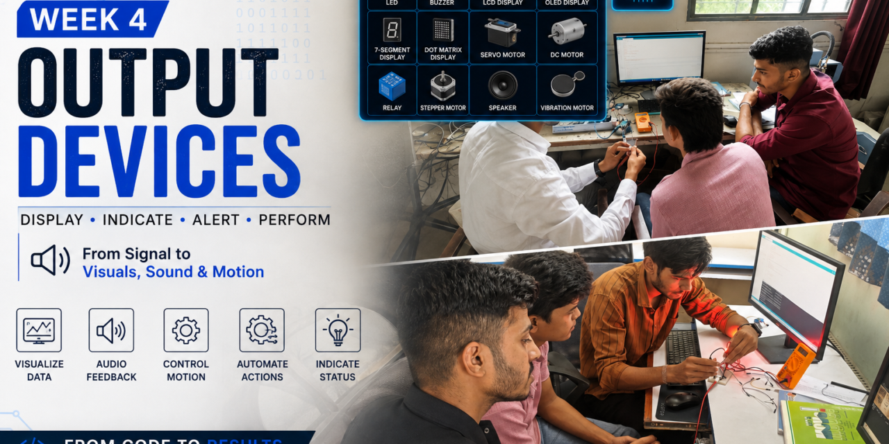
In Week 4, we studied output devices used in embedded systems and learned how they convert electrical signals from a microcontroller into physical outputs such as light, sound, motion, and display. We explored the working principles and internal structure of different output devices to understand how they operate and interact with electronic systems.
As part of this week’s assignment, we programmed a microcontroller to control various output devices and observed their behavior under different conditions. We also measured the voltage, current, and power consumption of these devices using a multimeter to evaluate their electrical characteristics and energy requirements. This helped us understand the practical aspects of selecting and using output devices in embedded system applications.
what is output devices ?
Output devices are electronic components that receive signals from a microcontroller or computer and convert them into physical actions or outputs. These outputs can be in the form of light, sound, movement, heat, or visual information. Output devices allow an embedded system to interact with the real world by performing a specific task based on the program running on the microcontroller.
Common examples of output devices include LEDs, buzzers, DC motors, servo motors, stepper motors, relays, and LCD/OLED displays. They are widely used in automation, robotics, IoT, and embedded systems to provide feedback, display information, or control mechanical devices.

individual assignment
output devices i used
1. Light Emitting Diode (LED)
The first output device I studied was the Light Emitting Diode (LED). An LED is a semiconductor electronic component that emits light when an electric current passes through it. It is one of the most commonly used output devices in embedded systems because it is simple, energy-efficient, and easy to control using a microcontroller.
In this study, I learned about the LED’s working principle, internal structure, pin configuration, operating voltage and current, and power consumption. I also programmed the microcontroller to blink the LED and observed its behavior.


Individual Task – Interfacing LED with XIAO ESP32-C3
In this individual task, I interfaced an LED with the Seeed Studio XIAO ESP32-C3 microcontroller. The LED was connected to one of the digital output pins through a current-limiting resistor. I wrote and uploaded a program to control the LED, making it blink at regular intervals. This activity helped me understand how a microcontroller controls an output device using digital signals. I also observed the LED’s operation and verified that the circuit and program worked correctly.

code for blinking LED
// LED Blink using XIAO ESP32-C3

const int ledPin = D10; // LED connected to D10

void setup() {
pinMode(ledPin, OUTPUT);
}

void loop() {
digitalWrite(ledPin, HIGH); // LED ON
delay(1000); // Wait 1 second

digitalWrite(ledPin, LOW); // LED OFF
delay(1000); // Wait 1 second
}Individual Assignment – RGB LED with XIAO ESP32-C3
In this individual assignment, I interfaced an RGB LED with the XIAO ESP32-C3 microcontroller to understand how multiple colors can be generated using Pulse Width Modulation (PWM). The RGB LED consists of three internal LEDs—Red, Green, and Blue—which were connected to separate GPIO pins of the XIAO ESP32-C3 through current-limiting resistors. By programming different PWM values for each color channel, I was able to produce various colors such as red, green, blue, yellow, cyan, magenta, and white. This experiment helped me understand the working principle of RGB LEDs, PWM-based brightness control, and color mixing techniques. The assignment also improved my skills in interfacing output devices with a microcontroller and writing Arduino code to control multiple outputs efficiently.


2. Buzzer
A buzzer is an electronic output device that converts electrical signals into sound. It is commonly used in embedded systems to produce beep sounds for alerts, alarms, notifications, and warnings. A microcontroller controls the buzzer by sending digital signals to turn it ON or OFF.
In this study, I learned about the buzzer’s working principle, internal structure, pin configuration, operating voltage, current consumption, and applications. I also interfaced the buzzer with the Seeed Studio XIAO ESP32-C3 and programmed it to generate a beep sound.
1. Active Buzzer
- Has a built-in oscillator.
- Produces a beep sound when DC power is applied.
- Easy to use because it only needs an ON/OFF signal from the microcontroller.
- Commonly used in alarms, timers, and simple notification systems.
2. Passive Buzzer
- Does not have a built-in oscillator.
- Requires a PWM (Pulse Width Modulation) signal from the microcontroller to produce sound.
- Can generate different tones and melodies by changing the frequency.
- Commonly used in music players, electronic toys, and projects that require different sound frequencies.


Individual Task – Interfacing Buzzer with XIAO ESP32-C3
In this individual task, I interfaced a buzzer with the Seeed Studio XIAO ESP32-C3 microcontroller. The buzzer was connected to a digital output pin, and I wrote and uploaded a program to generate a beep sound by turning the buzzer ON and OFF at regular intervals.
This activity helped me understand how a microcontroller controls an output device using digital signals. I also learned about the buzzer’s pin connections, working principle, and how it can be used to provide alerts, alarms, and notifications in embedded system applications.
Active Buzzer Pin Configuration
| Pin | Description |
|---|---|
| + (VCC) | Power Supply (3.3V–5V) |
| – (GND) | Ground |


code for buzzer
const int buzzerPin = D10; // Connect buzzer signal pin to D10

void setup() {
pinMode(buzzerPin, OUTPUT);
}

void loop() {
digitalWrite(buzzerPin, HIGH); // Buzzer ON
delay(500);

digitalWrite(buzzerPin, LOW); // Buzzer OFF
delay(500);
}
3. Displays
A display is an electronic output device used to show information such as text, numbers, symbols, and graphics. It helps users view the data generated by a microcontroller or electronic system. Displays are widely used in embedded systems to show sensor readings, system status, menus, and messages.
In this study, I learned about different types of displays, their working principle, internal structure, pin configuration, operating voltage, and applications. I also studied how displays can be interfaced with a microcontroller to present information clearly and efficiently.

Individual Task – Interfacing LCD Display with XIAO ESP32-C3
In this individual task, I interfaced a 16×2 LCD display with the Seeed Studio XIAO ESP32-C3 microcontroller. The LCD was connected using the I²C interface, which requires only four connections: VCC, GND, SDA, and SCL. I wrote and uploaded a program to display text on the LCD screen.
This activity helped me understand how a microcontroller communicates with a display to show information. I also learned the I²C communication protocol, LCD pin connections, and how to display custom messages using the Arduino IDE.

16×2 LCD (I²C) Pin Configuration
| Pin | Description |
|---|---|
| GND | Ground |
| VCC | Power Supply (5V) |
| SDA | I²C Data |
| SCL | I²C Clock |


code for lcd display
#include <Wire.h>
#include <LiquidCrystal_I2C.h>

// LCD I2C address (usually 0x27 or 0x3F)
LiquidCrystal_I2C lcd(0x27, 16, 2);

void setup() {
Wire.begin(); // Initialize I2C
lcd.init(); // Initialize LCD
lcd.backlight(); // Turn on backlight

lcd.setCursor(0, 0);
lcd.print("SARTHAK");

lcd.setCursor(0, 1);
lcd.print("XIAO ESP32-C3");
}

void loop() {
// Nothing to repeat
}
Individual Task – Interfacing Dot Matrix Display with XIAO ESP32-C3
In this individual task, I interfaced an 8×8 LED Dot Matrix Display with the Seeed Studio XIAO ESP32-C3 microcontroller. The dot matrix display was connected through a driver module, and I wrote and uploaded a program to display characters and simple patterns on the LED matrix.
This activity helped me understand how a microcontroller controls multiple LEDs simultaneously to form letters, numbers, and symbols. I also learned about the working principle of the dot matrix display, pin connections, and how it can be used to display scrolling text, animations, and graphical patterns in embedded system applications.

8×8 Dot Matrix (MAX7219 Module) Pin Configuration
| Pin | Description |
|---|---|
| VCC | Power Supply (5V) |
| GND | Ground |
| DIN | Data Input |
| CS | Chip Select (LOAD) |
| CLK | Clock |


code for dot matrix display
#include <MD_MAX72xx.h>

#include <SPI.h>

#define HARDWARE_TYPE MD_MAX72XX::FC16_HW

#define MAX_DEVICES 1

#define DATA_PIN 2

#define CLK_PIN 4

#define CS_PIN 3

MD_MAX72XX mx(HARDWARE_TYPE, DATA_PIN, CLK_PIN, CS_PIN, MAX_DEVICES);

byte heart[8] = {

  B00000000,

  B01100110,

  B11111111,

  B11111111,

  B11111111,

  B01111110,

  B00111100,

  B00011000

};

void setup() {

  mx.begin();

  mx.control(MD_MAX72XX::INTENSITY, 8);

  mx.clear();

  for (int row = 0; row < 8; row++) {

    for (int col = 0; col < 8; col++) {

      bool pixel = bitRead(heart[row], 7 - col);

      mx.setPoint(row, col, pixel);

    }

  }

}

void loop() {

}
Individual Task – Interfacing OLED Display with XIAO ESP32-C3
In this individual task, I interfaced a 0.96-inch OLED Display with the Seeed Studio XIAO ESP32-C3 microcontroller using the I²C communication protocol. The OLED display was connected using four pins: VCC, GND, SDA, and SCL. I wrote and uploaded a program to display text on the OLED screen.
This activity helped me understand how a microcontroller communicates with an OLED display using the I²C protocol. I also learned about the OLED display’s working principle, pin connections, and how it can be used to display text, numbers, symbols, and graphics in embedded system applications.

OLED Display Pin Configuration
| Pin | Description |
|---|---|
| GND | Ground |
| VCC | Power Supply (3.3V–5V) |
| SCL | I²C Clock |
| SDA | I²C Data |
code for oled display
#include <Wire.h>
#include <Adafruit_GFX.h>
#include <Adafruit_SSD1306.h>

#define SCREEN_WIDTH 128
#define SCREEN_HEIGHT 64
#define OLED_RESET -1

Adafruit_SSD1306 display(SCREEN_WIDTH, SCREEN_HEIGHT, &Wire, OLED_RESET);

void setup() {
Wire.begin();

if (!display.begin(SSD1306_SWITCHCAPVCC, 0x3C)) {
while (true);
}

display.clearDisplay();
display.setTextSize(2);
display.setTextColor(SSD1306_WHITE);
display.setCursor(10, 20);
display.println("Hello!");
display.display();
}

void loop() {
}
Individual Task – Interfacing 7-Segment Display with XIAO ESP32-C3
In this individual task, I interfaced a 7-segment display with the Seeed Studio XIAO ESP32-C3 microcontroller. The display was connected to the digital output pins of the microcontroller, and I wrote and uploaded a program to display numbers on the 7-segment display.
This activity helped me understand how individual LED segments are controlled to form numerical digits. I also learned about the working principle, pin connections, and applications of a 7-segment display in embedded system projects.

code for 7 segment display
// Segment pins: a, b, c, d, e, f, g
const int segPins[7] = {D0, D1, D2, D3, D4, D5, D6};

// Digit 0
byte digit0[7] = {1,1,1,1,1,1,0};

void setup() {
for (int i = 0; i < 7; i++) {
pinMode(segPins[i], OUTPUT);
}
}

void loop() {
// Display digit 0
for (int i = 0; i < 7; i++) {
digitalWrite(segPins[i], digit0[i]);
}
}
4.Servo Motor (SG90)
A servo motor is an output device that is used to control the position or angle of a rotating shaft with high accuracy. Unlike a DC motor, a servo motor can rotate to a specific angle, such as 0°, 90°, or 180°, based on the control signal received from a microcontroller.
The SG90 Servo Motor is a small, lightweight, and commonly used servo motor in embedded systems and robotics. It operates using PWM (Pulse Width Modulation) signals from a microcontroller and is widely used in robotic arms, automatic doors, camera pan-tilt systems, and other automation projects.
In this study, I learned about the SG90 servo motor’s working principle, internal structure, pin configuration, operating voltage, current consumption, and applications. I also interfaced the servo motor with the Seeed Studio XIAO ESP32-C3 and programmed it to rotate to different angles.

Individual Task – Interfacing SG90 Servo Motor with XIAO ESP32-C3
In this individual task, I interfaced an SG90 Servo Motor with the Seeed Studio XIAO ESP32-C3 microcontroller. The servo motor was connected to a PWM output pin, and I wrote and uploaded a program to rotate the motor between different angles.
This activity helped me understand how a microcontroller controls the angular position of a servo motor using PWM (Pulse Width Modulation) signals. I also learned about the servo motor’s working principle, pin connections, and its applications in robotics, automation, and embedded systems.


SG90 Servo Motor Pin Configuration
| Pin | Description |
|---|---|
| Brown | Ground (GND) |
| Red | Power Supply (4.8V–6V) |
| Orange | PWM Signal |
code for SG90servo motor
#include <Servo.h>

Servo myServo;

void setup() {
myServo.attach(D2); // Servo signal pin connected to D2
}

void loop() {
myServo.write(0); // Rotate to 0°
delay(1000);

myServo.write(90); // Rotate to 90°
delay(1000);

myServo.write(180); // Rotate to 180°
delay(1000);
}
5.Relay Module
A relay is an electronic output device that works as an electrically operated switch. It allows a low-voltage microcontroller, such as the Seeed Studio XIAO ESP32-C3, to safely control high-voltage or high-current devices without a direct electrical connection.
A relay consists of an electromagnetic coil, switching contacts (NO, NC, and COM), and an armature. When the microcontroller sends a signal to the relay, the coil becomes energized, causing the contacts to switch. This allows the connected electrical device to turn ON or OFF.
In this study, I learned about the relay’s working principle, internal structure, pin configuration, operating voltage, and applications. I also interfaced the relay module with the Seeed Studio XIAO ESP32-C3 and programmed it to switch ON and OFF automatically.

Individual Task – Interfacing Relay Module with XIAO ESP32-C3
In this individual task, I interfaced a 5V Relay Module with the Seeed Studio XIAO ESP32-C3 microcontroller. The relay module was connected to a digital output pin, and I wrote and uploaded a program to switch the relay ON and OFF at regular intervals.
This activity helped me understand how a microcontroller controls high-voltage or high-current devices using a relay. I also learned about the relay’s working principle, pin connections, and its applications in home automation, industrial control, and electrical switching systems..
Relay Module Pin Configuration
| Pin | Description |
|---|---|
| VCC | Power Supply (5V) |
| GND | Ground |
| IN | Control Signal from Microcontroller |


code for relay
const int relayPin = D2; // Relay IN pin connected to D2

void setup() {
pinMode(relayPin, OUTPUT);
}

void loop() {
digitalWrite(relayPin, HIGH); // Relay ON
delay(1000);

digitalWrite(relayPin, LOW); // Relay OFF
delay(1000);
}
Group assignment
BO motor (Battery Operated motor )
A BO (Battery Operated) motor is a small DC motor used in robotics and electronic projects. It works by converting electrical energy from a battery into mechanical movement. BO motors are commonly used in toy cars, robots, and small vehicles because they are easy to use, lightweight, and inexpensive. They usually operate on 3V to 12V and provide enough power to move small wheels. BO motors are popular among students for science and engineering projects because they are simple, reliable, and easy to connect.

BO Motor Pin Configuration
  BO DC Motor
┌─────────────┐
│             │
│             │
└─────────────┘
   |       |
  Pin 1   Pin 2
   (+)     (-)
BO DC motor using an Arduino Uno and L298N Motor Driver
In our group assignment, we interfaced a BO DC motor with an Arduino Uno using a CNC Shield to study the motor’s electrical characteristics. The motor was connected through the CNC Shield, and appropriate power was supplied to operate it safely. During the experiment, we measured the voltage across the motor and the current drawn while it was running using measuring instruments. Based on these measured values, we calculated the electrical power consumed by the motor using the formula Power (P) = Voltage (V) × Current (I). This assignment helped us understand motor interfacing, the use of a CNC Shield for motor control, electrical parameter measurement, and basic power calculations. It also improved our practical skills in circuit setup, testing, and data analysis.
| Arduino Uno | L298N Motor Driver | Purpose |
|---|---|---|
| D8 | IN1 | Motor direction control |
| D9 | IN2 | Motor direction control |
| D10 (PWM) | ENA | Motor speed control (PWM) |
| GND | GND | Common ground |
| 5V (if required for logic) | 5V | Logic power (depends on your module’s jumper settings) |


connect bo motor with arduino and measure its voltage and current


Experience
During this week’s assignment, I gained practical experience in interfacing different output devices with the Seeed Studio XIAO ESP32-C3 microcontroller. I successfully connected and programmed devices such as an LED, RGB LED, buzzer, 16×2 I²C LCD, OLED display, 8×8 dot matrix display, 7-segment display, SG90 servo motor, and relay module. Through these experiments, I learned how digital signals, PWM, and I²C communication are used to control different output devices. I also measured the voltage, current, and power consumption of selected devices using a multimeter, which improved my understanding of their electrical characteristics. This assignment strengthened my practical skills in circuit connections, programming, debugging, and troubleshooting while increasing my confidence in developing embedded system projects using the XIAO ESP32-C3.
end of week 4.