Introduction
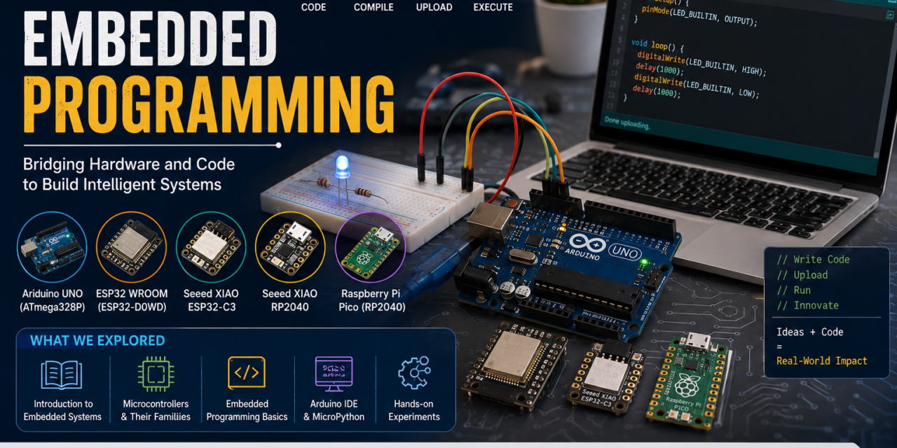
This week focused on learning the fundamentals of Embedded Programming and understanding how different microcontrollers are used in embedded systems. The objective was to study the architecture, specifications, toolchains, and development workflows of various microcontroller boards including Arduino Uno, ESP32-WROOM, XIAO ESP32-C3, XIAO RP2040, and Raspberry Pi Pico. Through the group assignment, I compared these boards and explored their programming environments using Arduino IDE and Thonny IDE. For the individual assignment, I studied microcontroller datasheets and developed programs to interact with input and output devices such as LEDs and LCD displays. This week helped me gain practical experience in embedded programming, hardware-software interaction, communication interfaces, and microcontroller-based system development.
Embedded System
An embedded system is a dedicated computing system designed to perform a specific function within a larger device. It consists of both hardware components, such as microcontrollers, sensors, and electronic circuits, and software that controls the operation of the device. Unlike general-purpose computers, embedded systems are optimized to carry out a particular task efficiently and reliably. They are commonly used in everyday applications such as home appliances, automotive systems, medical devices, traffic control systems, and smart electronics. During this week, I learned how embedded systems work by receiving inputs from sensors or users, processing the data through a microcontroller, and generating the required outputs to perform a desired action.


Embedded Programming
Embedded programming is the process of developing software for microcontrollers and embedded systems to perform specific tasks. It enables a microcontroller to receive inputs from sensors, switches, or other devices, process the information, and control outputs such as LEDs, motors, displays, and communication modules. Unlike general-purpose programming, embedded programming is focused on dedicated systems designed to perform a particular function efficiently and reliably.
During this week, I learned the fundamentals of embedded programming using Arduino IDE and Thonny IDE. I gained hands-on experience in writing, compiling, uploading, and testing programs on different microcontroller boards. Through these activities, I understood how software interacts with hardware to perform specific operations, making embedded programming an essential part of modern electronic and smart devices.
Microcontrollers
microcontroller is a compact integrated circuit that contains a processor, memory, and input/output peripherals on a single chip. It is designed to control specific tasks in embedded systems by receiving inputs, processing data, and generating outputs. Microcontrollers are widely used in automation systems, consumer electronics, robotics, IoT devices, and smart applications.
During this week, I explored and compared different microcontroller development boards, including Arduino Uno, ESP32-WROOM, XIAO ESP32-C3, XIAO RP2040, and Raspberry Pi Pico. I studied their features, architecture, communication interfaces, programming environments, and development workflows. This comparison helped me understand the capabilities of different microcontrollers and their applications in embedded system development.
Arduino Uno
The Arduino Uno is a beginner-friendly development board based on the ATmega328P microcontroller. It is widely used for learning electronics and embedded programming because of its simple architecture and ease of use. The board provides digital and analog input/output pins, making it suitable for interfacing sensors, LEDs, displays, and other electronic components. Arduino Uno is commonly used in educational, prototyping, and automation projects.

ESP32-WROOM
The ESP32-WROOM is a powerful microcontroller developed by Espressif Systems. It features built-in Wi-Fi and Bluetooth connectivity, making it ideal for IoT and wireless communication projects. The board offers high processing performance, multiple communication interfaces, and a large number of GPIO pins. It is widely used in smart home, automation, and connected device applications.

XIAO ESP32-C3
The XIAO ESP32-C3 is a compact development board based on the ESP32-C3 microcontroller and RISC-V architecture. It provides built-in Wi-Fi and Bluetooth Low Energy (BLE) connectivity while maintaining low power consumption. Despite its small size, it supports various communication interfaces such as UART, SPI, and I2C. It is suitable for portable IoT and embedded system applications.

XIAO RP2040
The XIAO RP2040 is a compact microcontroller board developed by Seeed Studio and powered by the RP2040 chip from Raspberry Pi. It features a dual-core ARM Cortex-M0+ processor and supports multiple communication protocols. The board is known for its small form factor, low power consumption, and high performance. It is commonly used in robotics, wearable devices, and embedded projects.

Raspberry Pi Pico
The Raspberry Pi Pico is a low-cost microcontroller board based on the RP2040 microcontroller. It provides a dual-core processor, multiple GPIO pins, and support for C/C++ and MicroPython programming. The board offers excellent performance for embedded applications while remaining affordable and easy to use. It is widely used in education, automation, robotics, and electronics prototyping projects.

Microprocessor
A microprocessor is an integrated circuit that acts as the central processing unit (CPU) of a computer or electronic system. It is responsible for executing instructions, performing calculations, and processing data. Unlike a microcontroller, a microprocessor typically requires external components such as RAM, ROM, and input/output devices to function properly. Microprocessors are commonly used in computers, laptops, smartphones, and other high-performance computing systems.
During this week, I learned the difference between microprocessors and microcontrollers. I understood that microprocessors are designed for complex and high-speed computing tasks, while microcontrollers are optimized for controlling specific functions in embedded systems. This comparison helped me better understand the role of processors in modern electronic devices.

Difference Between Microcontroller vs Microprocessor
| Feature | Microcontroller | Microprocessor |
|---|
| Definition | A compact computer system integrated on a single chip to perform specific control tasks. | A central processing unit (CPU) designed for general-purpose computing applications. |
| Main Components | Contains CPU, memory (RAM/Flash), and input/output peripherals on a single chip. | Primarily contains a CPU and requires external memory and peripheral devices. |
| Purpose | Designed for dedicated embedded applications. | Designed for running multiple applications and complex computing tasks. |
| Processing Power | Moderate processing capability. | High processing capability. |
| Power Consumption | Low power consumption. | Higher power consumption. |
| Cost | Generally low cost. | Comparatively more expensive. |
| Size | Compact and integrated design. | Larger overall system due to additional external components. |
| Memory | Built-in memory is available on the chip. | Depends on external RAM and storage devices. |
| Operating System | Usually operates without an OS or uses a lightweight RTOS. | Commonly runs full operating systems such as Windows, Linux, or macOS. |
| Speed | Suitable for real-time control applications. | Suitable for high-speed and complex processing tasks. |
| Applications | Smart appliances, robots, sensors, automation systems, and IoT devices. | Computers, laptops, servers, smartphones, and workstations. |
| Examples | Arduino (ATmega328P), ESP32, STM32, RP2040, PIC. | Intel Core Series, AMD Ryzen Series, Apple M-Series, ARM Cortex-A Processors. |
Conclusion
Different microcontroller families are designed to meet various application requirements, ranging from simple control systems to advanced embedded and IoT devices. Understanding the features and capabilities of each family helps in selecting the most suitable microcontroller for a project.
Microcontroller Families
| Microcontroller Family | Description | Key Features | Applications |
|---|
| AVR | A widely used microcontroller family known for its simplicity and ease of programming. | 8-bit architecture, low cost, beginner-friendly. | Arduino boards, educational projects, small automation systems. |
| PIC | A versatile family developed by Microchip Technology for embedded applications. | Wide product range, low power consumption, built-in peripherals. | Industrial automation, consumer electronics, embedded control systems. |
| ARM | A high-performance processor architecture used in modern embedded devices. | 32-bit/64-bit architecture, efficient performance, low power usage. | Smartphones, IoT devices, automotive systems, advanced embedded applications. |
| 8051 | One of the earliest and most widely studied microcontroller families. | Simple 8-bit architecture, easy to learn and implement. | Educational projects, basic control systems, industrial applications. |
| MSP430 | A low-power microcontroller family developed by Texas Instruments. | Ultra-low power consumption, 16-bit architecture. | Battery-powered devices, sensors, wearable electronics. |
| STM32 | An ARM Cortex-M based family developed by STMicroelectronics. | High performance, multiple communication interfaces, extensive peripherals. | Robotics, industrial automation, medical devices, IoT systems. |
| ESP Series | A family of wireless-enabled microcontrollers developed by Espressif Systems. | Built-in Wi-Fi and Bluetooth, low cost, IoT-ready. | Smart home devices, wireless communication, IoT applications. |
| RP Series | A family developed by Raspberry Pi Foundation, including the RP2040 microcontroller. | Dual-core processor, programmable I/O (PIO), flexible development options. | Embedded systems, education, robotics, DIY electronics projects. |
Summary
Microcontroller families provide different levels of performance, memory, connectivity, and power efficiency. Selecting the appropriate family depends on the application requirements, ranging from simple educational projects to advanced industrial and IoT systems. Understanding these families helps in choosing the most suitable platform for embedded system development.
Microcontrollers and Their Datasheet Overview
Arduino Uno
Features
- Based on ATmega328P microcontroller
- 8-bit AVR architecture
- 16 MHz clock speed
- 14 Digital I/O pins
- 6 Analog input pins
- 32 KB Flash Memory
- 2 KB SRAM
- Supports UART, SPI, and I2C communication
- Operates at 5V
Applications
- LED control projects
- Sensor interfacing
- Educational learning
- Home automation
- Robotics
- Embedded system prototyping
ESP32-WROOM
Features
- Based on ESP32 microcontroller
- 32-bit Xtensa LX6 architecture
- Dual-core processor
- Up to 240 MHz clock speed
- Built-in Wi-Fi
- Built-in Bluetooth (Classic + BLE)
- Up to 34 GPIO pins
- 4 MB Flash Memory
- 520 KB SRAM
- Supports UART, SPI, I2C, I2S, ADC, and DAC
Applications
- IoT projects
- Smart home automation
- Wireless sensor networks
- Robotics
- Industrial monitoring
- Web servers and IoT gateways
XIAO ESP32-C3
Features
- Based on ESP32-C3 microcontroller
- 32-bit RISC-V architecture
- Single-core processor
- Up to 160 MHz clock speed
- Built-in Wi-Fi (2.4 GHz)
- Bluetooth Low Energy (BLE 5.0)
- 11 GPIO pins
- 4 MB Flash Memory
- 400 KB SRAM
- USB Type-C interface
Applications
- IoT devices
- Smart home systems
- Wearable electronics
- Wireless communication projects
- Sensor networks
- Low-power embedded systems
XIAO RP2040
Features
- Based on RP2040 microcontroller
- Dual-core ARM Cortex-M0+ processor
- Up to 133 MHz clock speed
- 11 GPIO pins
- 2 MB Flash Memory
- 264 KB SRAM
- USB Type-C interface
- Supports UART, SPI, and I2C communication
- Compact form factor
Applications
- Embedded systems
- Robotics
- Sensor interfacing
- Automation projects
- Wearable devices
- Educational projects
Raspberry Pi Pico
Features
- Based on RP2040 microcontroller
- Dual-core ARM Cortex-M0+ processor
- Up to 133 MHz clock speed
- 26 GPIO pins
- 3 ADC inputs
- 16 PWM channels
- 2 MB Flash Memory
- 264 KB SRAM
- Supports UART, SPI, and I2C communication
- Micro-USB interface
Applications
- Embedded systems
- Robotics
- Home automation
- IoT projects
- Electronics prototyping
- Educational and DIY projects
Arduino IDE
What is Arduino IDE?
Arduino IDE (Integrated Development Environment) is a free and open-source software used to write, compile, and upload programs to Arduino boards and many other microcontroller platforms. It provides a simple and user-friendly interface that makes embedded programming easy for beginners as well as experienced developers. Arduino IDE supports various boards such as Arduino Uno, ESP32-WROOM, XIAO ESP32-C3, XIAO RP2040, and Raspberry Pi Pico.
During this week, I used Arduino IDE to develop and upload programs to different microcontroller boards. It helped me understand the complete embedded programming workflow, from writing code to testing the hardware.
Features of Arduino IDE
- Simple and easy-to-use interface
- Supports C/C++ programming language
- Built-in code editor with syntax highlighting
- One-click Verify (Compile) and Upload options
- Serial Monitor for debugging and communication
- Supports a wide range of development boards
- Large collection of built-in and third-party libraries
- Cross-platform support (Windows, Linux, and macOS)
Development Workflow in Arduino IDE
- Install Arduino IDE.
- Connect the microcontroller board.
- Select the board from the Tools > Board menu.
- Select the correct COM port.
- Write or open an Arduino sketch.
- Verify (Compile) the code.
- Upload the program to the board.
- Test the output using hardware or Serial Monitor.
- Modify the code and repeat the process if require
Conclusion
Arduino IDE provides a simple and efficient environment for embedded programming. Its easy-to-use interface, extensive library support, and compatibility with multiple development boards make it one of the most popular tools for learning and developing embedded system projects.
Thonny IDE & Installation of Thonny
What is Thonny IDE?
Thonny IDE is a free and beginner-friendly Integrated Development Environment (IDE) used for writing, running, and debugging Python and MicroPython programs. It is widely used for programming microcontroller boards such as ESP32, ESP32-C3, XIAO RP2040, and Raspberry Pi Pico. Thonny provides a simple interface that makes it easy to learn embedded programming and develop MicroPython-based projects.
Features of Thonny IDE
➤ Simple and easy-to-use interface.
➤ Supports Python and MicroPython programming.
➤ Built-in code editor with syntax highlighting.
➤ Integrated Shell for displaying program output.
➤ Easy debugging tools for identifying and fixing errors.
➤ Supports multiple MicroPython-compatible boards.
➤ Allows direct uploading and execution of code on microcontrollers.
➤ Available for Windows, Linux, and macOS.
Installation of Thonny IDE
Figure 1: Searching for the Thonny IDE download page using Google.

Figure 2: Downloading the Thonny IDE installer from the official Thonny website.

Figure 3: Installation process of Thonny IDE on Windows.

Figure 4: Thonny IDE launched successfully after installation.

Conclusion
The installation of Thonny IDE was completed successfully. After configuring the necessary settings, the software was ready to be used for MicroPython programming and embedded system development.
Number Systems
Binary Number System
The Binary Number System is a number system that uses only two digits: 0 and 1. It is the basic language of computers and microcontrollers because electronic circuits can easily represent two states such as ON/OFF or HIGH/LOW. All data, instructions, and calculations inside a microcontroller are processed in binary form.
Applications
➤ Computers and laptops
➤ Microcontrollers and embedded systems
➤ Digital electronics circuits
➤ Communication systems
➤ Memory and data storage devices
Examples
➤ Arduino Uno
➤ ESP32-WROOM
➤ Raspberry Pi Pico
➤ Digital clocks
➤ Calculators
Decimal Number System
The Decimal Number System is a base-10 number system that uses digits from 0 to 9. It is the most commonly used number system in everyday life because it is easy for humans to understand and perform calculations.
Applications
➤ Daily calculations
➤ Banking and finance
➤ Measurements and engineering calculations
➤ Scientific calculations
➤ Data representation for users
Examples
➤ Temperature readings
➤ Mobile phone numbers
➤ Currency values
➤ Distance measurements
➤ Time calculations
Hexadecimal Number System
The Hexadecimal Number System is a base-16 number system that uses digits 0–9 and letters A–F. It is commonly used in programming and embedded systems because it provides a compact and readable representation of binary data.
Applications
➤ Embedded programming
➤ Memory addressing
➤ Debugging and diagnostics
➤ Web color codes
➤ Computer system design
Examples
➤ Memory addresses in microcontrollers
➤ HTML color codes (#FF0000, #00FF00)
➤ MAC addresses
➤ Embedded system debugging tools
➤ Firmware development
Conclusion
Binary, Decimal, and Hexadecimal number systems are widely used in digital electronics and embedded programming. Binary is used internally by computers and microcontrollers, Decimal is used for human-readable calculations, and Hexadecimal provides a compact way to represent binary data. Understanding these number systems is important for working with embedded systems, programming, and digital electronics.
Individual Assignment
1. LED Blinking Using Binary Logic on Arduino Uno
For this individual assignment, I performed a simple LED blinking experiment using the Arduino Uno board. The objective of this activity was to understand how binary logic is used in embedded programming to control digital outputs. In a microcontroller, a binary value of 1 (HIGH) represents the ON state, while a binary value of 0 (LOW) represents the OFF state. Using these binary states, I programmed the onboard LED of the Arduino Uno to blink continuously. This activity helped me understand the basics of embedded programming, program uploading, and digital output control using a microcontroller.
Development Workflow
➤ Connected the Arduino Uno board to the computer using a USB cable.
➤ Opened Arduino IDE.
➤ Selected the Arduino Uno board and the correct COM port.
➤ Wrote the LED blinking program using HIGH and LOW states.
➤ Verified the code to check for errors.
➤ Uploaded the program to the Arduino Uno board.
➤ Observed the onboard LED blinking continuously.
➤ Tested and verified the output successfully.
void setup() { pinMode(LED_BUILTIN, OUTPUT);}void loop() { digitalWrite(LED_BUILTIN, HIGH); delay(1000); digitalWrite(LED_BUILTIN, LOW); delay(1000);}Result
The program was uploaded successfully to the Arduino Uno board. After execution, the onboard LED blinked continuously with a one-second delay between the ON and OFF states. This demonstrated how binary values can be used to control digital outputs in an embedded system. The activity was completed successfully and helped me gain practical experience in programming a microcontroller using Arduino IDE.


2. Blink LED Program on Raspberry Pi Pico
After learning the basics of Arduino IDE, I tested the programming workflow by creating a simple Blink LED program on the Raspberry Pi Pico. The objective of this activity was to understand how to write, compile, and upload a program to a microcontroller board. The program continuously turns the onboard LED ON and OFF with a fixed delay, demonstrating basic digital output control.
This activity helped me understand the complete development process, including board selection, code compilation, uploading the program, and testing the output on the hardware.
Development Workflow – Blink LED Program on Raspberry Pi Pico
➤ Connected the Raspberry Pi Pico to the computer using a USB cable.
➤ Opened Arduino IDE and selected the Raspberry Pi Pico board.
➤ Selected the correct COM port for the connected board.
➤ Created a new Arduino sketch and wrote the Blink LED program.
➤ Compiled the code to check for any errors.
➤ Uploaded the program to the Raspberry Pi Pico.
➤ Waited for the upload process to complete successfully.
➤ Observed the onboard LED blinking continuously with a fixed delay.
➤ Verified that the program was working as expected.
➤ Modified the code and tested different blinking intervals to understand the behavior of the microcontroller.
Code to Blink LED on Raspberry Pi Pico
void setup() { pinMode(LED_BUILTIN, OUTPUT);}void loop() { digitalWrite(LED_BUILTIN, HIGH); delay(1000); digitalWrite(LED_BUILTIN, LOW); delay(1000);}3. Soldering Pins on XIAO RP2040 and Raspberry Pi Pico
As part of the individual assignment, I performed soldering on the XIAO RP2040 and Raspberry Pi Pico development boards. The objective of this activity was to learn basic soldering techniques and prepare the boards for future embedded programming projects. I collected the XIAO RP2040 board, Raspberry Pi Pico board, header pins, soldering iron, and solder wire. The header pins were carefully aligned with the boards, and each pin was soldered to its corresponding pad using a soldering iron. After completing the soldering process, I inspected all solder joints to ensure proper electrical connections and correct alignment of the header pins. This activity helped me gain practical experience in electronics assembly and understand the importance of reliable solder joints for hardware development.
Result
The header pins were successfully soldered onto both the XIAO RP2040 and Raspberry Pi Pico boards. All connections were secure and properly aligned, making the boards ready for use in breadboard-based circuits and embedded programming applications.


4. Controlling the Onboard RGB LED of XIAO RP2040 Using Serial Monitor
As part of the individual assignment, I controlled the onboard RGB LED of the Seeed Studio XIAO RP2040 using the Arduino IDE Serial Monitor. The objective of this activity was to understand serial communication between the computer and the microcontroller. I connected the XIAO RP2040 board to the computer and uploaded a program that could receive color commands from the Serial Monitor. When a color name such as RED, GREEN, or BLUE was entered in the Serial Monitor, the onboard RGB LED changed to the corresponding color. This activity helped me understand how serial data can be used to control hardware components and how user input can be processed by a microcontroller in real time.
Result
The XIAO RP2040 successfully received commands from the Arduino IDE Serial Monitor and changed the color of the onboard RGB LED according to the entered text. For example, entering RED turned the LED red, entering GREEN turned it green, and entering BLUE turned it blue. This demonstrated successful serial communication and RGB LED control using the RP2040 microcontroller.
Code
#include <Adafruit_NeoPixel.h>#define LED_POWER 11 // Enable power to the RGB LED#define LED_PIN 12 // Data pin for the WS2812 RGB LED#define NUMPIXELS 1Adafruit_NeoPixel rgb(NUMPIXELS, LED_PIN, NEO_GRB + NEO_KHZ800);void setup() { pinMode(LED_POWER, OUTPUT); digitalWrite(LED_POWER, HIGH); // Turn ON power to RGB LED rgb.begin(); rgb.clear(); rgb.show(); Serial.begin(115200); while (!Serial); Serial.println("===== XIAO RP2040 RGB Control ====="); Serial.println("Commands:"); Serial.println("red"); Serial.println("green"); Serial.println("blue"); Serial.println("yellow"); Serial.println("cyan"); Serial.println("purple"); Serial.println("white"); Serial.println("off");}void loop() { if (Serial.available()) { String cmd = Serial.readStringUntil('\n'); cmd.trim(); if (cmd == "red") rgb.setPixelColor(0, rgb.Color(255, 0, 0)); else if (cmd == "green") rgb.setPixelColor(0, rgb.Color(0, 255, 0)); else if (cmd == "blue") rgb.setPixelColor(0, rgb.Color(0, 0, 255)); else if (cmd == "yellow") rgb.setPixelColor(0, rgb.Color(255, 255, 0)); else if (cmd == "cyan") rgb.setPixelColor(0, rgb.Color(0, 255, 255)); else if (cmd == "purple") rgb.setPixelColor(0, rgb.Color(255, 0, 255)); else if (cmd == "white") rgb.setPixelColor(0, rgb.Color(255, 255, 255)); else if (cmd == "off") rgb.setPixelColor(0, rgb.Color(0, 0, 0)); rgb.show(); }}
5. External LED Blinking Using Raspberry Pi Pico
As part of the individual assignment, I interfaced an external LED with the Raspberry Pi Pico and programmed it to blink using Arduino IDE. The objective of this activity was to understand how a microcontroller can control external output devices through its GPIO pins. I connected the LED to the Raspberry Pi Pico using the appropriate current-limiting resistor and uploaded a simple blink program. The microcontroller continuously switched the GPIO pin between HIGH and LOW states, causing the LED to turn ON and OFF repeatedly. This activity helped me understand digital output control, GPIO pin functionality, and hardware interfacing with the RP2040 microcontroller.
Result
The external LED blinked successfully at regular intervals after the program was uploaded to the Raspberry Pi Pico. The activity demonstrated successful interfacing between the RP2040 microcontroller and an external electronic component while providing practical experience with GPIO-based output control.
Code
const int ledPin = 15; // LED connected to GPIO 15void setup() { pinMode(ledPin, OUTPUT);}void loop() { digitalWrite(ledPin, HIGH); // LED ON delay(1000); digitalWrite(ledPin, LOW); // LED OFF delay(1000);}
6. LED Blinking on ESP32-WROOM Using MicroPython and Thonny IDE
To perform this activity, I first connected the ESP32-WROOM board to the computer and opened Thonny IDE. I configured the interpreter by selecting MicroPython (ESP32) and chose the correct communication port. After configuring the board, I installed the MicroPython firmware on the ESP32-WROOM through Thonny IDE. Once the installation was completed successfully, the board became ready for MicroPython programming. I then wrote a simple LED blinking program in Python and executed it using Thonny IDE. The program continuously switched the onboard LED between ON and OFF states with a fixed delay. This activity helped me understand the process of configuring a microcontroller for MicroPython, installing firmware, and controlling digital outputs through Python-based embedded programming.
from machine import Pinfrom time import sleepled = Pin(2, Pin.OUT)while True: led.on() sleep(1) led.off() sleep(1)Figure: Selecting ESP32-WROOM Variant and Configuring MicroPython Firmware in Thonny IDE

Figure: MicroPython Firmware Installation Progress on ESP32-WROOM

Figure: Successful Execution of LED Blinking Program on ESP32-WROOM

Group Assignment
As a group, we studied the datasheets of various microcontroller boards to understand their pin configurations, GPIO capabilities, memory architecture, communication protocols, and electrical specifications. We explored different embedded development platforms, including Arduino Uno, ESP32-WROOM, ESP32-C3, Seeed XIAO RP2040, and Raspberry Pi Pico. We compared their development workflows, programming environments, board configuration procedures, code compilation processes, and firmware uploading methods. This study helped us understand the strengths and applications of different microcontroller platforms used in embedded systems and IoT development.
Comparison between Micro-controllers
| Parameters | Arduino Uno | ESP32 WROOM | Seeed Studio XIAO ESP32-C3 | Seeed Studio XIAO RP2040 | Raspberry Pi Pico |
|---|---|---|---|---|---|
| Microcontroller | ATmega328P | ESP32-D0WD | ESP32-C3 | RP2040 | RP2040 |
| Core | 8-bit AVR | Dual-core Xtensa LX6 | Single-core RISC-V | Dual-core ARM Cortex-M0+ | Dual-core ARM Cortex-M0+ |
| Architecture | AVR 8-bit | 32-bit | 32-bit RISC-V | 32-bit ARM | 32-bit ARM |
| Clock Speed | 16 MHz | 240 MHz | 160 MHz | 133 MHz | 133 MHz |
| Operating Voltage | 5V | 3.3V | 3.3V | 3.3V | 3.3V |
| GPIO Voltage | 5V | 3.3V | 3.3V | 3.3V | 3.3V |
| Digital GPIO | 14 pins | 34 pins | 11 pins | 11 pins | 26 pins |
| PWM | 6 pins | 16 channels | 6 channels | 16 channels | 16 channels |
| Analog Input | 6 channels (10-bit ADC) | 18 channels (12-bit ADC) | 4 channels (12-bit ADC) | 4 channels (12-bit ADC) | 3 ADC channels |
| Communication | UART, SPI, I2C | UART, SPI, I2C, CAN | UART, SPI, I2C | UART, SPI, I2C | UART, SPI, I2C |
| WiFi | No | Yes | Yes | No | No |
| Bluetooth | No | Yes | Yes (BLE) | No | No |
| Programming Language | C/C++, Arduino IDE | C/C++, MicroPython, Arduino IDE | C/C++, MicroPython, Arduino IDE | C/C++, MicroPython | C/C++, MicroPython |
| On-board LED Pin | Pin 13 | GPIO 2 | GPIO 10 | GPIO 25 | GPIO 25 |
| Flash Memory | 32 KB | 4 MB | 4 MB | 2 MB | 2 MB |
| RAM | 2 KB | 520 KB | 400 KB | 264 KB | 264 KB |
| USB Interface | USB-B | Micro USB | USB-C | USB-C | Micro USB |
Result
The comparison of different microcontroller platforms helped us understand their architecture, specifications, and capabilities. We observed differences in processing power, memory, GPIO availability, communication interfaces, and wireless connectivity. The study showed that each board is designed for specific applications, ranging from basic embedded projects to advanced IoT and automation systems. This activity improved our understanding of microcontroller selection and the factors that should be considered when choosing a platform for a particular project.


Components and development workflow
| Parameter | Arduino Uno | ESP32-WROOM | Seeed Studio XIAO ESP32-C3 | Seeed Studio XIAO ESP32 RP2040 | Raspberry Pi Pico |
|---|---|---|---|---|---|
| Architecture | 8-bit AVR Harvard architecture | 32-bit Xtensa LX6 architecture (dual-core) | 32-bit RISC-V architecture (single-core) | 32-bit ARM Cortex-M0+ dual-core architecture | 32-bit ARM Cortex-M0+ dual-core architecture |
| Processor Speed | 16 MHz | Up to 240 MHz | Up to 160 MHz | Up to 133 MHz | Up to 133 MHz |
| Compiler | AVR-GCC | Xtensa GCC / ESP-IDF GCC | RISC-V GCC | ARM GCC | ARM GCC |
| Uploader Tool | avrdude | esptool.py | esptool.py | UF2 bootloader / drag-and-drop USB | UF2 bootloader / drag-and-drop USB |
| Firmware Format | HEX (.hex) | Binary (.bin) | Binary (.bin) | UF2 (.uf2), BIN | UF2 (.uf2), BIN |
| Connection Type | USB-to-Serial (ATmega16U2), UART, SPI, I²C | Wi-Fi, Bluetooth, UART, SPI, I²C, USB-UART | Wi-Fi, Bluetooth LE, USB, UART, SPI, I²C | USB, UART, SPI, I²C | USB, UART, SPI, I²C |
| Wireless Capability | None (requires external module) | Wi-Fi + Bluetooth | Wi-Fi + Bluetooth LE | None built-in | None built-in |
| Operating System Support | Bare-metal / simple scheduler | FreeRTOS, Bare-metal | FreeRTOS, Bare-metal | Bare-metal, MicroPython runtime | Bare-metal, MicroPython runtime |
| Memory | 32 KB Flash, 2 KB SRAM | Usually 4 MB Flash, 520 KB SRAM | 4 MB Flash, 400 KB SRAM | 2 MB Flash, 264 KB SRAM | 2 MB Flash, 264 KB SRAM |
| Best Use Case | Beginners, simple embedded projects | IoT, Wi-Fi devices, advanced embedded systems | Compact IoT, low-power wireless projects | Small embedded systems, robotics, learning | Embedded development, automation, robotics |

Result
The comparison of different microcontroller platforms helped us understand their architecture, specifications, and capabilities. We observed differences in processing power, memory, GPIO availability, communication interfaces, and wireless connectivity. The study showed that each board is designed for specific applications, ranging from basic embedded projects to advanced IoT and automation systems. This activity improved our understanding of microcontroller selection and the factors that should be considered when choosing a platform for a particular project.
Embedded Programming Project Ideas
Project Ideas Explored
➤ Smart Attendance System
➤ Smart Curtain System
➤ Smart Parking Assistant
➤ Smart Plant Monitoring System
➤ Automatic Pet Feeder
➤ Smart Charging Timer
➤ Home Automation System
➤ Smart Door Lock System
➤ Weather Monitoring Station
➤ IoT-Based Energy Monitoring System
➤ Smart Water Level Indicator
➤ Obstacle Detection Robot
➤ Fire and Gas Detection System
➤ Smart Street Light System
➤ RFID-Based Access Control System
Result
Through this activity, we explored different embedded programming project ideas and understood their working principles and applications. We observed how microcontrollers, sensors, actuators, and communication modules can be combined to develop smart and automated systems. This helped us gain a better understanding of real-world embedded system applications and future project development opportunities.
Conclusion
This week focused on understanding the fundamentals of embedded programming and microcontroller platforms. I studied different microcontroller boards, including Arduino Uno, ESP32-WROOM, XIAO ESP32-C3, XIAO RP2040, and Raspberry Pi Pico, and explored their architecture, features, applications, and development workflows. I learned about number systems such as Binary, Decimal, Octal, and Hexadecimal, which are widely used in embedded systems.
Through practical activities, I gained hands-on experience with Arduino IDE, Thonny IDE, MicroPython programming, soldering header pins, LED blinking, RGB LED control using Serial Monitor, and external component interfacing. I also learned how to install and configure MicroPython firmware on the ESP32-WROOM and successfully executed programs using Thonny IDE.
As part of the group assignment, I compared different microcontroller architectures, studied their datasheets, and explored various embedded programming project ideas and their applications. Overall, this week provided a strong foundation in embedded systems, microcontroller programming, hardware interfacing, and development tools, which will be useful for future electronics and IoT projects.
Weekly Summary
➤ Studied microcontrollers and microprocessors.
➤ Learned about different microcontroller families and architectures.
➤ Explored Arduino IDE and Thonny IDE.
➤ Installed and configured MicroPython on ESP32-WROOM.
➤ Performed LED blinking experiments on Arduino Uno, ESP32-WROOM, and Raspberry Pi Pico.
➤ Controlled the onboard RGB LED of XIAO RP2040 using Serial Monitor.
➤ Practiced soldering on XIAO RP2040 and Raspberry Pi Pico boards.
➤ Compared different microcontroller platforms and their features.
➤ Explored embedded programming project ideas and applications.
➤ Developed practical skills in embedded programming and hardware interfacing.